
Recommended
More Related Content
What's hot
What's hot (20)
Similar to Procedures for aluminothermic welding 1
Similar to Procedures for aluminothermic welding 1 (20)
Recently uploaded
Recently uploaded (20)
Procedures for aluminothermic welding 1
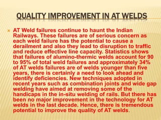
- 1. QUALITY IMPROVEMENT IN AT WELDS AT Weld failures continue to haunt the Indian Railways. These failures are of serious concern as each weld failure has the potential to cause a derailment and also they lead to disruption to traffic and reduce effective line capacity. Statistics shows that failures of alumino-thermic welds account for 90 to 95% of total weld failures and approximately 34% of AT welds failures are of welds younger than five years, there is certainly a need to look ahead and identify deficiencies. New techniques adopted in recent years such as combination joints and wide gap welding have aimed at removing some of the handicaps in the in-situ welding of rails. But there has been no major improvement in the technology for AT welds in the last decade. Hence, there is tremendous potential to improve the quality of AT welds.
- 2. AT WELDS DONE/DEFECTIVE REPORT INDIAN RAILWAYS LOCATED ON : ALL LINES PERIOD : 01/01/2014 - 25/08/2019 Railway Division No. of AT Welds Done No. of AT Welds Tested No. of AT Welds Untested No. of Defective AT Welds Defective Welds (%) CR BSL 35998 28854 7144 2383 8 CR CSTM 19920 15285 4635 1744 11 CR NGP 36692 29559 7133 4037 14 CR PA 19947 13504 6443 1525 11 CR SUR 25103 19105 5998 2387 12 CR Total 137660 106307 31353 12076 11 ECOR KUR 47787 26773 21014 7317 27 ECOR SBP 28667 17166 11501 2142 12 ECOR WAT 70741 42450 28291 3115 7 ECOR Total 147195 86389 60806 12574 15 ECR DHN 18334 12803 5531 1837 14 ECR DNR 15610 9564 6046 1142 12 ECR MGS 15213 9489 5724 1013 11 ECR SEE 20212 8488 11724 2562 30 ECR SPJ 4114 2909 1205 259 9 ECR Total 73483 43253 30230 6813 16 ER ASN 23795 19354 4441 1544 8 ER HWH 29265 22938 6327 2214 10 ER MLDT 12966 10267 2699 322 3 ER SDAH 19637 14678 4959 682 5 ER Total 85663 67237 18426 4762 7 MR MRD 2 0 2 0 0 MR Total 2 0 2 0 0 NCR AGC 24842 21486 3356 5232 24 NCR ALD 42483 37436 5047 5653 15 NCR JHS 26208 19891 6317 1889 9 NCR Total 93533 78813 14720 12774 16
- 3. AT WELDS DONE/DEFECTIVE REPORT INDIAN RAILWAYS LOCATED ON : ALL LINES PERIOD : 01/01/2014 - 25/08/2019 NER BSB 28494 12944 15550 2166 17 NER IZN 11536 7653 3883 1038 14 NER LJN 20023 14163 5860 1845 13 NER Total 60053 34760 25293 5049 15 NFR APDJ 29701 22221 7480 1805 8 NFR KIR 19303 11913 7390 885 7 NFR LMG 25224 12206 13018 416 3 NFR RNY 14516 8104 6412 37 0 NFR TSK 6910 2563 4347 54 2 NFR Total 95654 57007 38647 3197 6 NR DLI 53686 47365 6321 9244 20 NR FZR 23473 20028 3445 2175 11 NR LKO 41149 32455 8694 4842 15 NR MB 54917 49642 5275 9213 19 NR UMB 38613 33149 5464 4975 15 NR Total 211838 182639 29199 30449 17 NWR AII 14318 9628 4690 1626 17 NWR BKN 17573 15828 1745 3259 21 NWR JP 22942 18120 4822 2000 11 NWR JU 19541 16447 3094 1913 12 NWR Total 74374 60023 14351 8798 15 SCR BZA 51014 42437 8577 4973 12 SCR GNT 19320 15079 4241 3801 25 SCR GTL 46746 37203 9543 4200 11 SCR HYB 11456 9077 2379 809 9 SCR NED 7863 6271 1592 288 5 SCR SC 49146 41184 7962 966 2 SCR Total 185545 151251 34294 15037 10 SECR BSP 45955 33779 12176 7933 23 SECR NAG 36431 26894 9537 5931 22 SECR R 32286 21554 10732 5303 25 SECR Total 114672 82227 32445 19167 23
- 4. AT WELDS DONE/DEFECTIVE REPORT INDIAN RAILWAYS LOCATED ON : ALL LINES PERIOD : 01/01/2014 - 25/08/2019 SER ADA 22222 17177 5045 1626 9 SER CKP 33468 22974 10494 6383 28 SER KGP 32508 21477 11031 852 4 SER RNC 9675 7621 2054 1223 16 SER Total 97873 69249 28624 10084 15 SR MAS 19030 13410 5620 1612 12 SR MDU 16352 12300 4052 1188 10 SR PGT 23413 17154 6259 2306 13 SR SA 19497 16544 2953 2214 13 SR TPJ 14751 10760 3991 1057 10 SR TVC 23407 16207 7200 1147 7 SR Total 116450 86375 30075 9524 11 SWR MYS 13518 10638 2880 1755 16 SWR SBC 26231 21586 4645 4309 20 SWR UBL 18592 13715 4877 1054 8 SWR Total 58341 45939 12402 7118 15 WCR BPL 39929 30988 8941 5544 18 WCR JBP 54999 38715 16284 3478 9 WCR KTT 43392 35462 7930 6814 19 WCR Total 138320 105165 33155 15836 15 WR ADI 31124 26455 4669 2824 11 WR BCT 37686 30224 7462 2538 8 WR BRC 26462 20968 5494 2141 10 WR BVP 5751 4702 1049 283 6 WR RJT 17267 14217 3050 780 5 WR RTM 35584 29429 6155 3063 10 WR Total 153874 125995 27879 11629 9 Total 1844530 1382629 461901 184887 13
- 5. PROCEDURES FOR ALUMINOTHERMIC WELDING The rails are cut square and the gap to be welded is prepared within prescribed limits1. (If the rail ends are cut skewed, the gap will be non- uniform and the fusion of the rails will be asymmetric.)
- 6. The cut faces are cleaned with kerosene oil and a wire brush to remove rust, dust, or greasy material, etc. (Otherwise, this material may get fused with the weld material and this may render the weld defective.)
- 7. A 1m-long steel straightedge is used to align the running edge2 of the rail head. The rail ends are 'peaked' to accommodate contraction during solidification and cooling of the 'Thermit' steel. If 'rising' of the rails is not done, the joint will sag due to differential cooling of the rail head (where more material is available and hence the cooling is slower) and rail foot after cooling. A sagged joint gives bad riding and becomes a maintenance problem. Such a joint will be subject to larger stresses due to the dynamic augment. For lateral and vertical alignment, wedges are used.
- 8. Stands for crucible and torch are fixed on the railhead, at appropriate locations, on opposite sides of the welding gap and position and the height of the torch stand is checked and adjusted by placing the preheating burner or welding torch on it which is then removed and set aside for later use.
- 9. A set of prefabricated moulds of the appropriate rail section is selected and examined for suitability3. The rail profile of the mould is checked4 by placing the mould against the side of the rail to be welded. If required, small adjustments to the mould profile are made by rubbing the mould gently against the sides of the rail. Then the moulds are placed in the mould shoe (i.e., clamp), seating it properly using luting sand. The placement of the mould should be central over the gap as otherwise while pouring the molten metal, one rail end will get more heat than the other and the fusion of the metal at the other rail end may not be complete. The recess, if any, between the mould and the rail profile is sealed with luting sand. A slag bowl is attached to the mould shoe to collect the overflowing slag and molten metal during the pouring.
- 10. The magnesite lines crucible is housed at the correct height and alignment on the swiveling crucible stand. A closing pin is placed at the bottom over the opening. This pin's head is covered by about 5g of asbestos powder, so that it does not melt in contact with the molten metal and 'auto tapping' takes place.
- 11. The crucible is swung away from the rail and the 'portion' (self-igniting mixture which yields the molten metal) is poured into the crucible, heaped in a conical shape.
- 12. Using LPG (commercial use cylinders) and oxygen (or petrol and compressed air, an older technique, but still in use), the preheating burner or welding torch is lit and the flame is tuned. This torch is placed in its stand which is fixed over the gap, and the flame is directed into the mould through the central opening. The flame heats the rail ends and this is done for a specified time for each rail section and the pre-heating gases employed.
- 13. As the preheating is completed, the Thermit reaction is initiated by igniting a sparkler and putting it into the crucible. The reaction is allowed a specified time and the slag is allowed to be separated from the molten metal. Thereafter, the closing pin is tapped from the outside, thus discharging the metal into the top central cavity of the mould. Thereafter, the crucible and torch stands are removed.
- 14. The excess Thermit steel over the head of the rail (head riser) is removed after solidification (but when the metal is still red hot) by either manual chiseling or using hydraulic weld trimmers.
- 15. The remaining refractory material is removed and the steel vent risers attached to the collar of the foot of the weld are snapped off.
- 16. The wedges, etc., are removed, any fastenings that were removed, are re-fixed and the railhead is ground manually or using grinding machines.
- 17. Time for each activity Nominal Gap 25mm gap 50mm gap 75mm gap Gap Width 25±1mm 5±1mm 75±1mm Portion weight — 52kg section (kg) 10.8 13.5 22 Vertical alignment, either side of 1m straightedge 1.0-1.25mm high 1.25-1.50mm high 2.5-3.0mm high Lateral alignment (gauge side), at end of 1m straightedge 0-0 0-0 0-0 Heating time with petrol and air at 100-110 psi, 7-7.7kg/cm2 (minutes) 10-12 18-20 20-25 Heating time with LPG at 2.0- 2.5kg/cm2 and O2 at 7-8kg/cm2 (minutes) 2.0-2.5 2.5-3.0 3.0-4.0 Heating time with petrol and compressed air at 0.2-0.3 kg/cm2 (minutes) 5.0-5.5 10-11 Reaction time (seconds) 20±3 20±3 25±5 Mould waiting time (minutes) 04-05 06-07 10-12 Chipping time — manual (minutes) 4 05-06 08-09 Chipping time — weld trimmer (minutes) 0.5-1 0.5-1 0.5-2 Train passing time after pouring (minutes) 30 30 30 Vertical tolerance for finished weld �0.4mm at centre of 10cm straightedge �0.4mm at centre of 10cm straightedge �0.4mm at centre of 10cm straightedge Lateral tolerance for finished weld 0-0.3mm at centre of 10cm straightedge 0-0.3mm at centre of 10cm straightedge 0-0.3mm at centre of 10cm straightedge
- 18. THERMIT REACTION PRINCIPLE Thermit reaction details Aluminium reacts with iron oxides, particularly ferric oxide, in highly exothermic reactions, reducing the iron oxides to free iron, and forming a slag of aluminium oxide. 3Fe3O4+ 8Al = 4Al2O3+ 9Fe (3088°C, 719.3kCal↑) 3FeO + 2Al ⇒ Al2O3 + 3Fe (2500°C, 187.1kCal↑)
- 19. RAIL AND GAP RELATED Rail ends should be cleaned with wire brush and K.oil. Gap at rail joint prior to welding should be as under : SPW = 25 ± 1 mm Wider gap welding = 75 ± 1 mm Ensure correct alignment of rails prior to welding. The joint shall be kept higher by 3 to 4 mm for 72 UTS rails and 2 to 2.4 mm for higher UTS rails when measured at the end of 1m straight edge.
- 20. MOULD RELATED Ensure that prefabricated moulds are as per the welding technique, free from any moisture and cracks. 10. Prefabricated mould should be dressed w.r.t. actual rail profile being welded prior to their fixing. 11. Prefabricated mould should be centrally fixed and centre lines of two halves of prefabricated moulds should coincide with each other. 12. Ensure that mould shoe are in proper
- 21. MOULD AND LUTTING RELATED 13. Prefab mould/ shoe should be gently pressed to ensure flush fitting. 14. The gap between mould and the rail should be packed firmly with luting sand to prevent leakage of liquid weld metal. 15. Ensure that no foreign elements should be mixed in luting sand.
- 22. HEATING RELATED For proper and uniform preheating of both rail ends, vaporiser should be placed at proper height. Maximum height of Goosen neck from rail top should be 40mm. 17. Ensure that crucible is properly dried/ changed and repaired prior to pouring of portion.
- 23. CRUCIBLE RELATED Ensure that thimble is dry & free from moisture and thimble shape is round and dia is as under : 72 UTS rails - 14mm to 16mm 90 UTS rails - 18mm to 20mm Max. height of crucible from top of prefabricated mould should be 50 mm. Workability of pressure gauge fitted on petrol tank in case of air petrol heating and gauge fitted on oxygen & LPG cylinders in case of preheating with OxyLPG mixture, should be checked before carrying out welding of rails.
- 24. PORTION RELATED Ensure that portion bags are properly sealed & intact at the time of opening. 22. 90UTS portion should be used when welding of 72 UTS & 90 UTS rails is being done under unavoidable circumstances. 23. Portion being used should not be more than 2 year old provided packing is intact and there is no entry of moisture. 24. Portion should be properly stored at the site of welding so as to prevent entry of moisture
- 25. REACTION RELATED Ensure proper plugging of crucible 27. Portion should be thoroughly mixed in the pan before pouring it into the crucible for ignition. 28. Ensure reaction time of ignition of portion as 20 ± 3 seconds and portion in the crucible should be covered by crucible cap. 29. Molten metal should be tapped within 20 ± 3 seconds after start of reaction. 30. In case of 90 UTS rails, controlling of cooling should be ensured by post heating of rail & flange upto 50 cms on either side of mould box with the help of vaporisor.
- 26. POST WELDING RELATED Bottom half of prefab mould should be preserved at the time of demoulding to ensure controlled cooling. Chipping of hot metal should be done within 4 to 5 minutes of pouring of molten metal into the gap with the help of weld trimmer.
- 27. FINISHING RELATED Ensure final finishing of joint within 24 hours of its execution, to the following tolerances. a) Vertical alignment +1 mm (at the end of 1.0m - 0 mm straight edge) b) Lateral alignment = ± 0.5mm on 1.0 m straight edge. c) Finishing on sides of head of welded joint = ± 0.3 mm on 10cm straight edge d) Finishing at top table surface + 0.4 mm (at the end of 10 cm - 0.0 mm straight edge).
- 28. POST WELDING RELATED Ensure that there is no chisel mark on rail surface after final finishing. Ensure that 100m on either side of weld is destressed at the time of permanent repairs in LWR/ CWR panel as per instructions laid in LWR manual 1996. Moreover weld collars should be painted. Ensure that trimming of all new welds are done with the help of weld trimmer and grinding with the help of weld profile grinding trolley.
- 29. DON’TS OF AT WELDING OF RAILS 1. No ultrasonically untested rail should be welded. 2. No A.T. welding should be carried out by incompetent staff. 3. Don’t weld second hand rail without its end cropping. 4. Don’t cut the rails by flame cutting. 5. Don’t weld rails having battering/ hogging and without cleaning rail ends with wire brush and K. Oil. 6. Don’t weld rails having bolt holes at the ends.
- 30. DON’TS OF AT WELDING OF RAILS Don’t use consumable items like portion, luting sand if their validity has expired. 8. Don’t use worn out and defective welding equipments. 9. Don’t carry out in-situ welding during inadequate traffic block. 10. Don’t use damaged prefabricated moulds. 11. Don’t add any extra material in the premixed luting sand. 12. Don’t use loose portion. 13. Don’t add or subtract any material from the portion.
- 31. DON’TS OF AT WELDING OF RAILS 14. Don’t carry out welding in rain. 15. Don’t pour portion into the crucible without mixing it properly in the pan. 16. Don’t pass the first train over newly welded joint without its rough grinding joggle fish plating and wooden block support, in case of in-situ welding. 17. Don’t pass the train before 30 minutes after pouring the molten metal. 18. Don’t carry out welding at incorrect pressures of compressed air petrol mixture, O2 and LPG (in case of OxyLPG preheating)
- 32. DON’TS OF AT WELDING OF RAILS 19. Don’t remove/ loosen the wedge used for aligning the rail ends prior to 20 minutes after trimming i.e. prior to weld had fully cooled down. (MOST IMPORTANT). 20 min time starts after stripping not pouring. 20. Don’t remove/ loosen the rail tensor prior to weld has fully cooled down. 21. Don’t store the portion at a place having dampness.
- 33. PAINTING OF WELD COLLAR Painting of weld collar should be done on all the welds to protect them against corrosion immediately after the welding. In service, painting of thermit welds should be carried as per following frequency : Once in four years in areas not prone to corrosion. Every year at locations prone to corrosion.
- 34. PAINTING PROCEDURE FOR NEW WELDS In normal areas After surface preparation, one coat of ready mixed paint, brushing bituminous black conforming to IS: 9862-1981 is applied on the welded area upto 10 cms on either side. After eight hours drying, also a second coat of the same paint is applied. In corrosion prone areas After surface preparation, one coat of high build epoxy paint (two pack) conforming to RDSO specification No. M&C/PCN111/88 is applied on the welded area up to 10 cm on either side.
- 35. MAJOR DEFECTS IN AT WELDING Major Defects in AT Welding The common defects in thermit welds due to deficiency in execution are as under: a) Lack of Fusion (i) Causes Improper cleaning of rail ends. Inadequate or non-uniform pre-heating Inadequate or non-uniform gap. Delayed tapping. This is serious defects and makes the weld weak.
- 36. PREVENTIVE ACTION FOR LACK OF FUSION (ii) Preventive Action for lack of fusion Maintain the welding gap between rail ends specified in the approved parameters of the technique. Never attempt to weld a gap, which is too wide, with standard mould. Take care to centralise the mould to the gap. Never try to fit both mould halves simultaneously. Take care to fit mould both vertical and central to the weld gap. Do not incline mould to the vertical. Do not try to weld worn to new rail, or rails dissimilar depth with standard mould. Rail ends should be properly cleaned. The tapping shall be done within the time specified for that particular technique. Special care shall be given to the tank pressure, efficiency of burner and flame condition for achieving required rail temperature within the stipulated time.
- 37. MAJOR DEFECTS IN AT WELDING b) Slag inclusion (i) Causes Early tapping. Pouring without plug in position. (ii) Preventive Action After preheating fit the sand core with the riser aperture of the mould and press down lightly. Ensure that the crucible is positioned centrally the over the sand core and the crucible does not move during the thermit reaction. Never allow the thermit steel to pour directly into either pouring gate.
- 38. MAJOR DEFECTS IN AT WELDING c) High porosity in weld metal (gross/local) (i) Causes Use of damp crucible. Use of damp mould. Use of damp portion. (ii) Preventive Action Crucible must be pre-heated before first weld of the day to remove any moisture. Damp portions and damp moulds should not be used in welding.
- 39. MAJOR DEFECTS IN AT WELDING d) Sand Inclusion (i) Causes Dropping of luting sand into mould. Broken pieces of mould getting into the mould. (ii) Preventive Action Take care when sealing the mould with luting sand. It must not be allowed to drop into the mould. If the welder is careful, these defects can be easily avoided.
- 40. DEFECTS IN AT WELDING
- 42. DEFECTS IN AT WELDING
- 43. PRECAUTIONS TO AVOID DEFECTS IN AT WELDED RAIL JOINTS (i) It should be ensured that the portion being used matches with type and chemistry of rail. (ii) Rail ends should be square. (iii) Alignment of rail ends should be perfect as checked by straight edge. (iv) Rail ends should be properly cleaned with kerosene oil and wire brushes. (v) Stop watch should be provided to the welding supervisor at each welding site. (vi) Pressure in the tanks/cylinder should be properly maintained during pre- heating. (vii) Correct gap between rail ends at head, web and foot shall be ensured. (viii) Correct preheating time for rail ends shall be ensured. (ix) Tightness of clips fitted with hose connections to compressor tank and burner shall be checked before commencing preheating. (x) Nozzles of burners shall be cleaned periodically to avoid back fire. (xi) The tapping shall be done within the time specified for that particular technique. For special type of welding i.e. 75mm gap, combination joint etc. the time of reaction and tapping shall be as stipulated by RDSO for that particular welding technique. (xii) Boiling portion shall be tapped outside the welding gap (xiii) No moist portion/ torned bag portion shall be used for welding.
- 44. PRECAUTIONS TO AVOID DEFECTS IN AT WELDED RAIL JOINTS (xiv) Dampness in moulds can lead to porosity and early fatigue failure of welds. (xv) Only those contractual agencies as have clearance from the RDSO/Railway Board can execute welding work. Supply of portions must be from sources approved by RDSO/Railway Board. (xvi) Many weld failures show evidence of badly cut rail ends. The evenness and verticality of a rail cut depends solely upon the skill of the welder. With portable disc cutters, less skill is required to produce good cut. (xvii) A Thermit weld done in situ shall be joggle fish plated. (para 502 of IRPWM & USFD Manual Revised -2012). Anti corrosive painting of all the Thermit welds should be carried out as per provision of manual for fusion welding of rails by AT process. (xviii) The compressor tank shall be kept 2 to 3 meter away from heating torch to prevent fire hazard. (xix) Welders should be provided with gloves and coloured glasses.
- 45. HALF MOON DEFECT IN AT WELDS DETECTION OF HALF MOON CRACK IN AT WELDS Half moon cracks are found to be present in the rail foot center of AT welds and are oriented transversely. In AT welds these defects are associated with fins formed during AT welding. For avoiding such defects and consequent failure in service, procedure laid down for visual examination by sectional SSE/JE/P.Way and USFD examination by SSE/P.Way / USFD as per para 8.7 and 8.1 (b) of USFD manual revised -2012, should be followed.
- 46. PRECAUTIONS AND PREVENTIONS DURING MAINTENANCE OF TRACK GENERALLY FOR WELD FAILURE IN WINTER SEASON (i) Do De-stressing of LWR/CWR whenever due. Special attention should be given to the location where high temperature de-stressing was done for BCM or other planned work and de- stressing to be done again at appropriate temp. (ii) Duty hours of Keymen should be changed so that failures, if any, can be detected in time. Keymen and patrolmen should be suitably trained to detect fractures and to take protective measures. (iii) Weld Fracrture prone locations of LWR/CWR should be identified and measures like recoupment of missing fitting and de- stressing at lower temperatures for winter season may be taken as per requirement. (iv) It should be ensured that there are no arrears of USFD testing. (v) All Arrangements for cold weather patrolling should be made as per para 9.1.2 (ii) of LWR Manual.
- 47. PRECAUTIONS AND PREVENTIONS DURING MAINTENANCE OF TRACK GENERALLY FOR WELD FAILURE IN WINTER SEASON (vi) A close watch on rail temperatures should be kept and temperature record register should also be maintained by the SSE (P-Way). (vii) Rails having corroded flange should be kept under special watch. (viii) Inspection of LWRs/CWRs & SEJs by SSE/JE (P-Way) as per para 8.1.5(i) of LWR Manual. (ix) DFWR welds more than three month old to be removed either by replacing the rail or by 75 mm gap AT welding. (As per para 8.14 of manual for ultrasonic testing of Rails & Welds) (x) Systematic attention to cupped weld and replacement of corroded /wheel burnt or worn out rails should be completed before onset of winter.
- 48. PHOTOS OF WELD FAILURES
- 49. PHOTOS OF BAD EXECUTION OF WELDS
- 50. THE END This presentation is prepared by LKO division of NR on 25 Aug 2019 in the office of SSE(P. Way)/Varanasi West for presenting in IPWE seminar at LKO on 26 Aug 2019.