
Recommended
More Related Content
Similar to FLOW.pptx
Similar to FLOW.pptx (20)
More from ssuser868fa0
More from ssuser868fa0 (11)
Recently uploaded
Recently uploaded (20)
FLOW.pptx
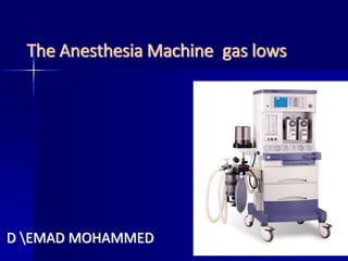
- 1. The Anesthesia Machine gas lows D EMAD MOHAMMED
- 4. The Anesthesia Machine FLOW High Intermediate Low Pressure Circuit
- 5. High Pressure System Receives gasses from the high pressure E cylinders attached to the back of the ane sthesia machine (2200 psig for O2, 745 ps ig for N2O) Consists of: Hanger Yolk (reserve gas cylinder holder) Check valve (prevent reverse flow of gas) Cylinder Pressure Indicator (Gauge) Pressure Reducing Device (Regulator) Usually not used, unless pipeline gas sup ply is off
- 6. E Size Compressed Gas Cy linders Cylinder Characteri stics Oxygen Nitrous Oxide Carbon Dioxide Air Color White (green) Blue Gray Black/White (yellow) State Gas Liquid and gas Liquid and gas Gas Contents (L) 625 1590 1590 625 Empty Weight (kg) 5.90 5.90 5.90 5.90 Full Weight (kg) 6.76 8.80 8.90 Pressure Full (psig) 2000 750 838 1800
- 7. Hanger Yolk Hanger Yolk: orients and supports the cylinder, pr oviding a gas-tight seal a nd ensuring a unidirectio nal gas flow into the mac hine Index pins: Pin Index Safe ty System (PISS) is gas sp ecificprevents accident al rearrangement of cylin ders (e.g.. switching O2 a nd N2O)
- 8. Pressure Reducing Device Reduces the high and variable pressures found in a cylinder to a lower and more constant pressure fou nd in the anesthesia machine (45 psig) Reducing devices are preset so that the machine us es only gas from the pipeline (wall gas), when the p ipeline inlet pressure is 50 psig. This prevents gas use from the cylinder even if the cylinder is left open (i.e. saves the cylinder for back up if the wall gas pipeline fails)
- 9. Pressure Reducing Device Cylinders should be kept closed routin ely. Otherwise, if the wall gas fails, the machine will automatically switch to th e cylinder supply without the anestheti st being aware that the wall supply ha s failed (until the cylinder is empty to o).
- 10. Intermediate FLOW Syste m Receives gasses from the regulator or the h ospital pipeline at pre ssures of 40-55 psig.
- 11. Limitations of Fail-Safe D evices/Alarms These devices prevent hypoxia from some p roblems occurring upstream in the machine circuitry (disconnected oxygen hose, low ox ygen pressure in the pipeline and depletion of the oxygen cylinder) Equipment problems that occur downstream (for example leaks or partial closure of the o xygen flow control valve) are not prevented by these devices.
- 12. Second-Stage Reducing D evice Located just upstream of the flow cont rol valves Receives gas from the pipeline inlet or the cylinder reducing device and reduc es it further to 26 psig for N2O and 14 psig for O2
- 13. The end