SlideShare a Scribd company logo
1 of 148
Download to read offline
Operator Manual
Generator Set
KTA38G5/G9 Engine with PowerCommand®
3.3 Control
C1000 D5
C1100 D5B
C1250 D5A
English
5-2012 A042V240 (Issue 1)
Original Instructions
Table of Contents
1. IMPORTANT SAFETY INSTRUCTIONS ....................................................................................... 1
1.1 Warning, Caution and Note Styles Used In This Manual ....................................................... 1
1.2 General Information ................................................................................................................ 1
1.2.1 General Safety Precautions......................................................................................... 1
1.3 Generator Set Safety Code .................................................................................................... 2
1.3.1 Moving Parts Can Cause Severe Personal Injury Or Death........................................ 3
1.3.2 Positioning of Generator Set....................................................................................... 3
1.3.3 Container Lifting – ISO 3874:1997 .............................................................................. 3
1.4 Electrical Shocks and Arc Flashes Can Cause Severe Personal Injury or Death.................. 4
1.4.1 NFPA Equivalent Standards ........................................................................................ 4
1.4.2 AC Supply and Isolation............................................................................................... 5
1.5 Fuel And Fumes Are Flammable............................................................................................ 5
1.5.1 Spillage ....................................................................................................................... 5
1.5.2 Fluid Containment....................................................................................................... 5
1.5.3 Do Not Operate in Flammable and Explosive Environments ...................................... 6
1.6 Exhaust Gases Are Deadly..................................................................................................... 6
1.6.1 Exhaust Precautions................................................................................................... 6
2. INTRODUCTION............................................................................................................................ 7
2.1 About This Manual.................................................................................................................. 7
2.2 Schedule of Abbreviations ...................................................................................................... 7
2.3 Related Literature ................................................................................................................... 8
2.4 After Sales Services................................................................................................................ 9
2.4.1 Maintenance................................................................................................................ 9
2.4.2 Warranty....................................................................................................................... 9
2.4.3 How to Obtain Service ............................................................................................... 10
3. SYSTEM OVERVIEW .................................................................................................................. 11
3.1 Generator Set Identification .................................................................................................. 11
3.1.1 Nameplate - Open Generator Set.............................................................................. 11
3.1.2 Nameplate - Enclosed Generator Set........................................................................ 12
3.2 Generator Set Components.................................................................................................. 12
3.3 Generator Set Rating............................................................................................................ 13
3.4 Engine................................................................................................................................... 13
3.4.1 Engine Data ............................................................................................................... 14
3.5 Sensors................................................................................................................................. 15
3.6 Normal Duty Air Cleaner....................................................................................................... 15
3.7 Pyrometers - Engine Exhaust............................................................................................... 15
3.8 Heaters ................................................................................................................................. 16
3.8.1 Heater Supply and Isolation...................................................................................... 16
3.9 Mains (Utility) Powered Battery Charger .............................................................................. 16
3.10 Alarm Module...................................................................................................................... 16
A042V240 (Issue 1) i
Table of Contents 5-2012
3.11 System Options................................................................................................................... 17
3.11.1 Heavy Duty Air Cleaner ........................................................................................... 17
3.11.2 PowerCommand Universal Annunciator.................................................................. 17
3.11.3 Circuit Breaker ......................................................................................................... 18
4. CONTROL SYSTEM - POWERCOMMAND 3.3.......................................................................... 19
4.1 Control System Description .................................................................................................. 19
4.1.1 Control System Panel ................................................................................................ 19
4.1.2 Control System Panel ................................................................................................ 20
4.1.3 Operating Modes........................................................................................................ 20
4.1.4 Power On and Sleep Modes...................................................................................... 22
4.2 Operator Panel...................................................................................................................... 23
4.2.1 Selection Buttons ....................................................................................................... 25
4.2.2 Default Settings.......................................................................................................... 25
4.2.3 Lamp Indicators.......................................................................................................... 25
4.2.4 Lamp (LED) Test Button ............................................................................................ 26
4.2.5 Reset Button .............................................................................................................. 26
4.2.6 CB (Circuit Breaker) Open Button ............................................................................. 26
4.2.7 CB (Circuit Breaker) Closed Button ........................................................................... 26
4.2.8 Graphical Display and Buttons................................................................................... 26
4.3 Operator Panel - Initial Operator Menu ................................................................................ 29
4.3.1 Initial Menu Data........................................................................................................ 29
4.4 Operator Panel - Generator Set Data Operator Menu.......................................................... 31
4.4.1 Generator Set Data.................................................................................................... 31
4.5 Operator Panel - Engine Data Operator Menu..................................................................... 33
4.5.1 Engine Data ............................................................................................................... 33
4.5.2 History/About Menu.................................................................................................... 35
4.6 Operator Panel - Alternator Data Operator Menu................................................................. 37
4.6.1 Alternator Data........................................................................................................... 37
4.7 Operator Panel - Faults and Warnings Menus ..................................................................... 38
4.7.1 Shutdown Fault Menu................................................................................................ 38
4.7.2 Fault Messages.......................................................................................................... 40
4.7.3 Fault Acknowledgement............................................................................................. 40
4.7.4 Warning Fault Menu................................................................................................... 40
4.7.5 Faults History Data Operator Menu ........................................................................... 41
4.8 Operator Panel - Adjust Menu .............................................................................................. 43
4.9 Operator Panel - Genset Setup Data Operator Menu .......................................................... 45
4.10 Operator Panel - Paralleling Status Menu .......................................................................... 46
4.11 Operator Panel - Paralleling/Basic Setup Menu ................................................................. 49
4.12 Selecting Operating Modes................................................................................................. 53
4.12.1 Mode Change Access.............................................................................................. 53
4.12.2 Selecting Manual Run Mode.................................................................................... 54
4.12.3 Selecting Auto Mode................................................................................................ 54
4.12.4 Selecting Off Mode .................................................................................................. 55
5. OPERATION - POWERCOMMAND 3.3 ...................................................................................... 57
5.1 Safety.................................................................................................................................... 57
ii A042V240 (Issue 1)
5-2012 Table of Contents
5.2 Introduction ........................................................................................................................... 57
5.3 Maintenance ......................................................................................................................... 58
5.4 Operating Recommendations ............................................................................................... 58
5.4.1 Running-in.................................................................................................................. 58
5.4.2 No Load Operation.................................................................................................... 58
5.4.3 Exercise Period.......................................................................................................... 58
5.4.4 Low Operating Temperatures .................................................................................... 58
5.4.5 High Operating Temperatures ................................................................................... 58
5.4.6 Operating Conditions for Prime, Standby and Continuous Power Ratings .............. 59
5.4.7 De-Rating Factors..................................................................................................... 60
5.5 Generator Set Operation....................................................................................................... 60
5.5.1 Sequence of Operation.............................................................................................. 62
5.6 Starting.................................................................................................................................. 62
5.6.1 Initial Pre-start Checks.............................................................................................. 63
5.6.2 Operator’s Pre-start Checks ...................................................................................... 64
5.6.3 Starting at Operator Panel (Manual Run Mode) ........................................................ 64
5.6.4 Starting from Remote Location (Auto Mode) ............................................................. 65
5.6.5 Cold Starting with Loads........................................................................................... 65
5.7 Stopping................................................................................................................................ 66
5.7.1 Stopping at Operator Panel (Manual Mode).............................................................. 66
5.7.2 Stopping from Operator Panel (Auto Mode) .............................................................. 67
5.7.3 Stopping from Remote Location (Auto Mode) .......................................................... 67
5.7.4 Emergency Stop (Code 1433 or 1434)..................................................................... 67
5.8 Paralleling Operation ............................................................................................................ 68
5.8.1 Speed and Voltage Matching..................................................................................... 68
5.8.2 Operation When in Parallel ....................................................................................... 68
5.8.3 Generator Set Application Type................................................................................. 69
5.8.4 Standalone Application .............................................................................................. 70
5.8.5 Synchronize Only....................................................................................................... 70
5.8.6 Isolated Bus Only....................................................................................................... 71
5.8.7 Power Transfer Control (Option)................................................................................ 72
5.8.8 Conditions for Each Paralleling State ........................................................................ 77
6. MAINTENANCE ........................................................................................................................... 87
6.1 Locking the Generator Set Out of Service............................................................................ 88
6.1.1 Immobilizing for Safe Working ................................................................................... 88
6.2 Periodic Maintenance ........................................................................................................... 89
6.2.1 Periodic Maintenance Schedule ................................................................................ 89
6.3 Daily or Refueling Maintenance Procedures ........................................................................ 92
6.3.1 General Information ................................................................................................... 92
6.3.2 Engine Operation Report .......................................................................................... 92
6.4 Cooling System..................................................................................................................... 93
6.4.1 Coolant Level - Check .............................................................................................. 93
6.4.2 Cooling Fan - Inspection............................................................................................ 94
6.4.3 Drive Belt - Inspection................................................................................................ 95
6.4.4 Radiator - Check........................................................................................................ 96
A042V240 (Issue 1) iii
Table of Contents 5-2012
6.5 Engine Oil – Level Check ..................................................................................................... 96
6.6 Fuel System.......................................................................................................................... 97
6.6.1 Fuel Level ................................................................................................................. 98
6.6.2 Fuel/Water Separator - Drain.................................................................................... 98
6.7 Fluid Containment................................................................................................................. 98
6.7.1 Spillage ..................................................................................................................... 99
6.7.2 Fluid Containment..................................................................................................... 99
6.8 Hoses and Fuel Lines - Check ........................................................................................... 100
6.9 Air Intake System................................................................................................................ 100
6.9.1 Air Cleaner Service Indicator ................................................................................... 100
6.9.2 Normal Duty Air Cleaner.......................................................................................... 101
6.9.3 Heavy Duty Air Cleaner ........................................................................................... 102
6.10 Exhaust System................................................................................................................ 104
6.11 Generator Set Output - AC Electric System ..................................................................... 104
6.12 DC Electrical System ........................................................................................................ 104
6.13 Lead Acid Batteries........................................................................................................... 105
6.13.1 Storage................................................................................................................... 105
6.13.2 Safety Precautions................................................................................................. 105
6.13.3 Battery Maintenance .............................................................................................. 106
6.13.4 Electrolyte - Specific Gravity and Temperature ..................................................... 108
6.13.5 Battery Replacement.............................................................................................. 109
6.13.6 Electrolyte Levels and Bench Charging Rates ...................................................... 109
6.13.7 Battery Fault Finding.............................................................................................. 111
7. TROUBLESHOOTING ............................................................................................................... 113
7.1 Control System ................................................................................................................... 113
7.2 Safety Considerations......................................................................................................... 113
7.3 Fault Finding ....................................................................................................................... 114
7.4 Status Indicators - PowerCommand 3.3............................................................................. 114
7.4.1 Not in Auto .............................................................................................................. 115
7.4.2 Remote Start ........................................................................................................... 115
7.4.3 Warning ................................................................................................................... 115
7.4.4 Shutdown Status ..................................................................................................... 115
7.4.5 Generator Set Running ........................................................................................... 115
7.5 Fault/Status Codes - PowerCommand 3.3 ......................................................................... 115
7.5.1 Fault Messages........................................................................................................ 115
7.5.2 Fault Acknowledgement........................................................................................... 115
7.5.3 Fault Codes - PowerCommand 3 .3 ........................................................................ 116
7.5.4 Customer Input Faults.............................................................................................. 127
7.6 Line Circuit Breaker ............................................................................................................ 132
8. BATTERY CHARGER................................................................................................................ 133
8.1 Mains (Utility) Powered Battery Charger - Wall-Mounted (Option)..................................... 133
8.1.1 Boost........................................................................................................................ 133
8.1.2 Specifications - 5 Amp and 10 Amp......................................................................... 134
8.2 Mains (Utility) Powered Battery Charger – Set Mounted.................................................... 134
8.2.1 Specifications - 5 Amp ............................................................................................. 135
iv A042V240 (Issue 1)
5-2012 Table of Contents
8.3 Circuits................................................................................................................................ 135
9. MANUFACTURING FACILITIES................................................................................................ 137
9.1 How to Obtain Service........................................................................................................ 137
A042V240 (Issue 1) v
Table of Contents 5-2012
This page is intentionally blank.
vi A042V240 (Issue 1)
1 Important Safety Instructions
SAVE THESE INSTRUCTIONS - This manual contains important instructions that should be
followed during installation and maintenance of the generator set and batteries.
Safe and efficient operation can be achieved only if the equipment is properly operated
and maintained. Many accidents are caused by failure to follow fundamental rules and
precautions.
1.1 Warning, Caution and Note Styles Used In This
Manual
The following safety styles and symbols found throughout this manual indicate potentially
hazardous conditions to the operator, service personnel or the equipment.
DANGER: Warns of a hazard that will result in severe personal injury or death .
WARNING: Warns of a hazard that may result in severe personal injury or death .
CAUTION: Warns of a hazard or an unsafe practice that can result in product or property
damage .
NOTE: A short piece of text giving information that augments the current text .
1.2 General Information
This manual should form part of the documentation package supplied by Cummins Power
Generation with specific generator sets. In the event that this manual has been supplied in
isolation please contact your authorized distributor.
NOTE: It is in the Operator’s interest to read and understand all Warnings and
Cautions contained within the documentation relevant to the generator set,
its operation and daily maintenance .
1.2.1 General Safety Precautions
WARNING: Coolants under pressure can cause severe scalding. Do not open a radiator
or heat exchanger pressure cap while the engine is running. Let the engine
cool down before removing the coolant pressure cap. Turn the cap slowly
and do not open it fully until the pressure has been relieved.
WARNING: Moving parts can cause severe personal injury or death and hot exhaust
parts can cause severe burns. Make sure all protective guards are properly in
place before starting the generator set.
WARNING: Used engine oils have been identified by some state and federal agencies to
cause cancer or reproductive toxicity. Do not ingest, breathe the fumes, or
contact used oil when checking or changing engine oil.
WARNING: Operation of equipment is unsafe when mentally or physically fatigued. Do
not operate equipment in this condition, or after consuming any alcohol or
drug.
A042V240 (Issue 1) 1
1. Important Safety Instructions 5-2012
WARNING: Substances in exhaust gases have been identified by some state and federal
agencies to cause cancer or reproductive toxicity. Do not breath in or come
into contact with exhaust gases.
WARNING: Flammable liquids can cause fire or explosion. Do not store fuel, cleaners,
oil, etc. near the generator set.
WARNING: Wear hearing protection when going near an operating generator set .
WARNING: Hot metal parts can cause severe burns. Avoid contact with the radiator,
turbo charger, and exhaust system.
WARNING: Maintaining or installing a generator set can cause severe personal injury.
Wear personal protective equipment such as safety glasses, protective
gloves, hard hats, steel-toed boots, and protective clothing when working on
equipment.
WARNING: Ethylene glycol, used as engine coolant, is toxic to humans and animals.
Clean up coolant spills and dispose of used antifreeze in accordance with
local environmental regulations.
WARNING: Starting fluids, such as ether, can cause explosion and generator set engine
damage. Do not use.
CAUTION: Do not step on the generator set when entering or leaving the generator room.
Parts can bend or break leading to electrical shorts, or to fuel, coolant, or exhaust
leaks.
CAUTION: To prevent accidental or remote starting while working on the generator set,
disconnect the negative (-) battery cable at the battery using an insulated wrench.
CAUTION: Make sure that rags are not left on or near the engine.
CAUTION: Make sure the generator set is mounted in a manner to prevent combustible
materials from accumulating under the unit .
CAUTION: Accumulated grease and oil can cause overheating and engine damage presenting
a potential fire hazard. Keep the generator set clean and repair any oil leaks
promptly.
CAUTION: Before performing maintenance and service procedures on enclosed generator
sets, make sure the service access doors are secured open.
CAUTION: Keep the generator set and the surrounding area clean and free from obstructions.
Remove any debris from the set and keep the floor clean and dry.
NOTE: Keep multi-class ABC fire extinguishers handy. Class A fires involve ordinary
combustible materials such as wood and cloth. Class B fires involve
combustible and flammable liquid fuels and gaseous fuels. Class C fires
involve live electrical equipment. (Refer to NFPA No. 10 in applicable region.)
1.3 Generator Set Safety Code
Before operating the generator set, read the manuals and become familiar with them and the
equipment. Safe and efficient operation can be achieved only if the equipment is properly
operated and maintained. Many accidents are caused by failure to follow fundamental rules
and precautions.
2 A042V240 (Issue 1)
5-2012 1. Important Safety Instructions
WARNING: Improper operation and maintenance can lead to severe personal injury or
loss of life and property by fire, electrocution, mechanical breakdown, or
exhaust gas asphyxiation. Read and follow all Safety Precautions, Warnings
and Cautions throughout this manual and the documentation supplied with
your generator set .
WARNING: Lifting and repositioning of the generator set must only be carried out using
suitable lifting equipment, shackles, and spreader bars, in accordance with
local guidelines and legislation, by suitably trained and experienced
personnel. Incorrect lifting can result in severe personal injury, death and/or
equipment damage. For more information, contact your authorized distributor
.
1.3.1 Moving Parts Can Cause Severe Personal Injury Or Death
· Keep your hands, clothing, and jewelry away from moving parts.
· Before starting work on the generator set, disconnect the battery charger from its AC
source, then disconnect the starting batteries using an insulated wrench, negative (–) cable
first. This will prevent accidental starting.
· Make sure that fasteners on the generator set are secure. Tighten supports and clamps;
keep guards in position over fans, drive belts, etc.
· Do not wear loose clothing or jewelry in the vicinity of moving parts or while working on
electrical equipment. Loose clothing and jewelry can become caught in moving parts.
· If any adjustments must be made while the unit is running, use extreme caution around hot
manifolds, moving parts, etc.
1.3.2 Positioning of Generator Set
The area for positioning the set should be adequate and level and the area immediately around
the set must be free of any flammable material.
WARNING: On an enclosed generator set, the canopy doors must be locked before re-
positioning and they must remain locked during transportation and sitting .
1.3.3 Container Lifting – ISO 3874:1997
Lifting should be carried out using the ISO container lifting blocks in either the top or bottom of
the container using methods defined in ISO 3874:1997.
1.3.3.1 Lifting using a Fork Lift
If a forklift is to be used to move the containerized generator set, the forks must be inserted
under the base of the container. The forklift pockets must only be used to lift an empty
container. Refer to the General Arrangement drawings for further reference information including
the Centre of Gravity.
A042V240 (Issue 1) 3
1. Important Safety Instructions 5-2012
1.4 Electrical Shocks and Arc Flashes Can Cause
Severe Personal Injury or Death
WARNING: Any work with exposed energized circuits with potentials of 50 Volts AC or
75 Volts DC or higher poses a significant risk of electrical shock and
electrical arc flash. These silent hazards can cause severe injuries or death.
Refer to standard NFPA 70E or equivalent safety standards in corresponding
regions for details of the dangers involved and for the safety requirements.
Guidelines to follow when working on de-energized electrical systems:
· Use proper PPE. Do not wear jewelry and make sure that any conductive items are
removed from pockets as these items can fall into equipment and the resulting short circuit
can cause shock or burning. Refer to standard NFPA 70E for PPE standards.
· De-energize and lockout/tagout electrical systems prior to working on them.
Lockout/Tagout is intended to prevent injury due to unexpected start-up of equipment or
the release of stored energy. Please refer to the lockout/tagout section for more
information.
· De-energize and lockout/tagout all circuits and devices before removing any protective
shields or making any measurements on electrical equipment.
· Follow all applicable regional electrical and safety codes.
Guidelines to follow when working on energized electrical systems:
NOTE: It is the policy of Cummins Inc. to perform all electrical work in a de-
energized state. However, employees or suppliers may be permitted to
occasionally perform work on energized electrical equipment only when
qualified and authorized to do so and when troubleshooting, or if de-
energizing the equipment would create a greater risk or make the task
impossible and all other alternatives have been exhausted.
NOTE: Exposed energized electrical work is only allowed as per the relevant
procedures and must be undertaken by a Cummins authorized person with
any appropriate energized work permit for the work to be performed while
using proper PPE, tools and equipment. In summary:
·
· Do not tamper with or bypass interlocks unless you are authorized to do
so.
·
· Understand and assess the risks - use proper PPE. Do not wear jewelry
and make sure that any conductive items are removed from pockets as
these items can fall into equipment and the resulting short circuit can
cause shock or burning. Refer to standard NFPA 70E for PPE standards.
·
· Make sure that an accompanying person who can undertake a rescue is
nearby.
1.4.1 NFPA Equivalent Standards
BS EN 12601:2010 Reciprocating internal combustion engine driven generating sets — Safety.
International Relationships EN 12601:2010 Identical BS EN 60204-1:2006+A1:2009 Safety of
machinery. Electrical equipment of machines. General requirements. International Relationships
EN 60204-1:2006 Identical, IEC 60204-1:2005 Modified.
4 A042V240 (Issue 1)
5-2012 1. Important Safety Instructions
1.4.2 AC Supply and Isolation
It is the sole responsibility of the customer to provide AC power conductors for connection to
load devices and the means to isolate the AC input to the terminal box; these must comply to
local electrical codes and regulations. Refer to the wiring diagram supplied with the generator
set.
NOTE: Local electrical codes and regulations (for example BS EN 12601:2001) may
require the installation of a disconnect means for the generator set, either on
the generator set or where the generator set conductors enter a facility .
NOTE: The AC supply must have the correct over current and earth fault protection
according to local electrical codes and regulations. This equipment must be
earthed (grounded) .
The disconnecting device is not provided as part of the generator set, and Cummins Power
Generation accepts no responsibility for providing the means of isolation.
1.5 Fuel And Fumes Are Flammable
Fire, explosion, and personal injury or death can result from improper practices.
· DO NOT fill fuel tanks while the engine is running, unless the tanks are outside the engine
compartment. Fuel contact with hot engine or exhaust is a potential fire hazard.
· DO NOT permit any flame, cigarette, pilot light, spark, arcing equipment, or other ignition
source near the generator set or fuel tank.
· Fuel lines must be adequately secured and free of leaks. Fuel connection at the engine
should be made with an approved flexible line. Do not use copper piping on flexible lines
as copper will become brittle if continuously vibrated or repeatedly bent.
· Be sure all fuel supplies have a positive shutoff valve.
· Be sure the battery area has been well-ventilated prior to servicing near it. Lead-acid
batteries emit a highly explosive hydrogen gas that can be ignited by arcing, sparking,
smoking, etc.
1.5.1 Spillage
Any spillage that occurs during fueling or during oil top-off or oil change must be cleaned up
before starting the generator set.
1.5.2 Fluid Containment
If fluid containment is incorporated into the bedframe, it must be inspected at regular intervals.
Any liquid present should be drained out and disposed of in line with local health and safety
regulations. Failure to perform this action may result in spillage of liquids which could
contaminate the surrounding area.
Any other fluid containment area must also be checked and emptied, as described above.
NOTE: Where spillage containment is not part of a Cummins supply, it is the
responsibility of the installer to provide the necessary containment to
prevent contamination of the environment, especially water courses/sources
.
A042V240 (Issue 1) 5
1. Important Safety Instructions 5-2012
1.5.3 Do Not Operate in Flammable and Explosive Environments
Flammable vapor can cause an engine to overspeed and become difficult to stop, resulting in
possible fire, explosion, severe personal injury and death. Do not operate a generator set where
a flammable vapor environment can be created by fuel spill, leak, etc., unless the generator set
is equipped with an automatic safety device to block the air intake and stop the engine. The
owners and operators of the generator set are solely responsible for operating the generator set
safely. Contact your authorized Cummins Power Generation distributor for more information.
1.6 Exhaust Gases Are Deadly
· Provide an adequate exhaust system to properly expel discharged gases away from
enclosed or sheltered areas and areas where individuals are likely to congregate. Visually
and audibly inspect the exhaust daily for leaks per the maintenance schedule. Make sure
that exhaust manifolds are secured and not warped. Do not use exhaust gases to heat a
compartment.
· Be sure the unit is well ventilated.
WARNING: Engine exhaust and some of its constituents are known to the state of
California to cause cancer, birth defects, and other reproductive harm .
1.6.1 Exhaust Precautions
WARNING: Exhaust pipes and charge air pipes are very hot and they can cause severe
personal injury or death from direct contact or from fire hazard .
WARNING: Hot exhaust gas can cause burns resulting in severe personal injury .
The exhaust outlet may be sited at the top or bottom of the generator set. Make sure that the
exhaust outlet is not obstructed. Personnel using this equipment must be made aware of the
exhaust position. Position the exhaust away from flammable materials - in the case of exhaust
outlets at the bottom, make sure that vegetation is removed from the vicinity of the exhaust.
WARNING: Inhalation of exhaust gases can result in serious personal injury or death. Be
sure deadly exhaust gas is piped outside and away from windows, doors, or
other inlets to buildings. Do not allow to accumulate in habitable areas .
WARNING: Contaminated insulation is a fire risk which can result in severe personal
injury .
The exhaust pipes may have some insulating covers fitted. If these covers become
contaminated by fuel or oil, they must be replaced before the generator set is run.
To minimize the risk of fire, make sure the following steps are observed:
· Make sure that the engine is allowed to cool thoroughly before topping off the oil or
draining the fuel filters.
· Clean the exhaust pipe thoroughly.
6 A042V240 (Issue 1)
2 Introduction
2.1 About This Manual
The purpose of this manual is to provide the users with sound, general information. It is for
guidance and assistance with recommendations for correct and safe procedures. Cummins
Power Generation (CPG) cannot accept any liability whatsoever for problems arising as a result
of following recommendations in this manual.
The information contained within the manual is based on information available at the time of
going to print. In line with Cummins Power Generation policy of continuous development and
improvement, information may change at any time without notice. The users should therefore
make sure that before commencing any work, they have the latest information available.
Users are respectfully advised that, in the interests of good practice and safety, it is their
responsibility to employ competent persons to carry out any installation work. Consult your
authorized distributor for further installation information. It is essential that the utmost care is
taken with the application, installation, and operation of any engine due to their potentially
hazardous nature. Careful reference should also be made to other Cummins Power Generation
literature. A generator set must be operated and maintained properly if you are to expect safe
and reliable operation.
Should you require further assistance, contact your authorized distributor.
2.2 Schedule of Abbreviations
This list is not exhaustive. For example, it does not identify units of measure or acronyms that
appear only in parameters, event/fault names, or part/accessory names.
AmpSentry and InPower are trademarks of Cummins Inc. PowerCommand is a registered
trademark of Cummins Inc.
ACRONYM DESCRIPTION ACRONYM DESCRIPTION
AC Alternating Current LED Light-emitting Diode
AMP AMP, Inc., part of Tyco Electronics Mil Std Military Standard
ASTM American Society for Testing and MMHG Millimeters of Mercury
Materials (ASTM International)
ATS Automatic Transfer Switch NC Not Connected
AVR Automatic Voltage Regulator NC Normally Closed
AWG American Wire Gauge NFPA National Fire Protection Agency
CAN Controlled Area Network NO Normally Open
CB Circuit Breaker NWF Network Failure
CE Conformité Européenne OEM Original Equipment Manufacturer
CFM Cubic Feet per Minute OOR Out of Range
CGT Cummins Generator Technologies OORH / ORH Out of Range High
CMM Cubic Meters per Minute OORL / ORL Out of Range Low
CT Current Transformer PSI Pounds per square inch
A042V240 (Issue 1) 7
2. Introduction 5-2012
ACRONYM DESCRIPTION ACRONYM DESCRIPTION
DC Direct Current PB Push Button
ECM Engine Control Module PC Personal Computer
ECS Engine Control System PCC PowerCommand®
Control
EMI Electromagnetic interference PGI Power Generation Interface
EN European Standard PGN Parameter Group Number
EPS Engine Protection System PI Proportional/Integral
E-Stop Emergency Stop PID Proportional/Integral/Derivative
FAE Full Authority Electronic PLC Programmable Logic Controller
FMI Failure Mode Identifier PMG Permanent Magnet Generator
FSO Fuel Shutoff PT Potential Transformer
Genset Generator Set PTC Power Transfer Control
GCP Generator Control Panel PWM Pulse-width Modulation
GND Ground RFI Radio Frequency Interference
HMI Human-machine Interface RH Relative Humidity
IC Integrated Circuit RMS Root Mean Square
INHG Inches of Mercury RTU Remote Terminal Unit
ISO International Organization for SAE Society of Automotive Engineers
Standardization
kPA kilo-Pascal SPN Suspect Parameter Number
LBNG Lean-burn Natural Gas SW_B+ Switched B+
LCD Liquid Crystal Display UL Underwriters Laboratories
LCL Low Coolant Level UPS Uninterruptible Power Supply
LCT Low Coolant Temperature
2.3 Related Literature
Before any attempt is made to operate the generator set, the operator should take time to read
all of the manuals supplied with the generator set, and to familiarize themselves with the
warnings and operating procedures.
CAUTION: A generator set must be operated and maintained properly if you are to expect safe
and reliable operation. The Operator manual includes a maintenance schedule and
a troubleshooting guide.
The Health and Safety manual must be read in conjunction with this manual for the
safe operation of the generator set:
· Health and Safety Manual (0908-0110)
The relevant manuals appropriate to your generator set are also available, the documents below
are in English:
· Operator Manual for KTA38G5/G9 with PowerCommand 3.3 Control (A042V240)
· Installation Manual for KTA38G5/G9 with PowerCommand 3.3 Control (A042V241)
8 A042V240 (Issue 1)
5-2012 2. Introduction
· Generator Set Service Manual for KTA38G5/G9 with PowerCommand 3.3 Control
(A042V242)
· Controller Service Manual for PowerCommand 3.3 Control (0900-0670)
· Engine Operation & Maintenance Manual for KTA38 (3810497)
· Alternator Service Manual for HC Alternators (0900-9904,A040J849)
· Alternator Service Manual for P7 Alternators (0900-9902,A040J850)
· Specification and Data Sheet (For engineering data specific to the generator set)
· Application Manual T-030, Liquid Cooled Generator Sets (For application information)
· Parts Manual for KTA38 G5 (A042T993)
· Parts Manual for KTA38 G9 (A042W603)
· Standard Repair Times - CL Family (0900-0913)
· Recommended Spares List (RSL) for C1000 D5 (A042W934)
· Recommended Spares List (RSL) for C1100 D5B (A042W935)
· Recommended Spares List (RSL) for C1250 D5A (A042W936)
· Warranty Manual (F1117)
· Global Commercial Warranty Statement (A028U870)
Contact your authorized distributor for more information regarding related literature for this
product.
2.4 After Sales Services
Cummins Power Generation offer a full range of maintenance and warranty services.
2.4.1 Maintenance
WARNING: Incorrect service or parts replacement can result in severe personal injury,
death, and/or equipment damage. Service personnel must be trained and
experienced to perform electrical and/or mechanical service.
For customers who wish to have their generator sets expertly serviced at regular intervals your
local distributor offers a complete maintenance contract package. This covers all items subject
to routine maintenance and includes a detailed report on the condition of the generator set. In
addition, this can be linked to a 24-hour call-out arrangement, providing year-round assistance if
necessary. Specialist engineers are available to maintain optimum performance levels from
customer’s generator sets, and it is recommended that maintenance tasks are only undertaken
by trained and experienced technicians provided by your authorized distributor.
2.4.2 Warranty
For details of the warranty coverage for your generator set, refer to the Global Commercial
Warranty Statement (A028U870).
Extended warranty coverage is also available. In the event of a breakdown, prompt assistance
can normally be given by factory trained service technicians with facilities to undertake all minor
and many major repairs to equipment on site.
A042V240 (Issue 1) 9
2. Introduction 5-2012
For further warranty details, contact your authorized distributor.
NOTE: Damage caused by failure to follow the correct coolant recommendations will
not be covered by the warranty. Please contact your authorized distributor.
2.4.2.1 Warranty Limitations
For details of the warranty limitations for your generator set, refer to the warranty statement
applicable to the generator set.
2.4.3 How to Obtain Service
When a product requires servicing, contact your nearest Cummins Power Generation distributor.
To locate your local Cummins Power Generation distributor, refer to www.cumminspower.com
and select Distributor Locator. When contacting your distributor, always supply the complete
Model, Specification, and Serial Number as shown on the nameplate.
10 A042V240 (Issue 1)
3 System Overview
This section provides an overview of the Generator Set.
3.1 Generator Set Identification
Each generator set is provided with a nameplate similar to that shown below. This provides
information unique to each generator set.
3.1.1 Nameplate - Open Generator Set
FIGURE 1. TYPICAL OPEN GENERATOR SET NAMEPLATE
A042V240 (Issue 1) 11
3. System Overview 5-2012
3.1.2 Nameplate - Enclosed Generator Set
FIGURE 2. TYPICAL ENCLOSED GENERATOR SET NAMEPLATE
3.2 Generator Set Components
The main components of a typical KTA38 engine generator set are shown below, and referred
to within this section.
There are various options listed although they may not be available for all models.
12 A042V240 (Issue 1)
5-2012 3. System Overview
No Description No Description
1 Radiator (Not indicated)
2 Engine Battery and Tray
3 Controller Alarm Module
4 Battery Battery Charger
5 Alternator Engine Coolant Heater
6 Bed Frame Alternator Heater
FIGURE 3. TYPICAL KTA38 ENGINE GENERATOR SET
3.3 Generator Set Rating
For details of your generator set rating, refer to the Generator Set nameplate. Refer to Section
5.4 on page 58 for operation at temperatures or altitudes above those stated on the nameplate.
3.4 Engine
For additional engine specific information, refer to the relevant engine manual for your generator
set.
A042V240 (Issue 1) 13
3. System Overview 5-2012
No. Description
1 Oil filler cap
2 Fan belt
3 Dipstick
FIGURE 4. TYPICAL ENGINE COMPONENTS (KTA38)
3.4.1 Engine Data
3.4.1.1 Acoustic Information
3.4.1.1.1 Acoustic Information (1500 rpm)
TABLE 1. ACOUSTIC DATA (1500 RPM)
Model C1000 D5 C1100 D5B C1250 D5A
Engine KTA38G5 KTA38G5 KTA38G9
Enclosed Set Acoustic Data – LWA 105 105 105
(Based on using a standard Cummins’
canopy, and 50 Hz set operating with
doors closed) 1, 2
Open Set Acoustic Data – dB(A) at 1m 98.3 98.3 101.3
3
– SPL (or enclosed set with doors
open)
1. Doors closed figures are measured using 2000/14/EC guaranteed sound power levels
2. Based on 75% load
3. Doors closed figures are measured using 2000/14/EC guaranteed sound power levels
For Noise Spectrum Figures, refer also to your authorised distributor.
In line with the Cummins Power Generation policy of continuous improvement, these figures are subject to change.
14 A042V240 (Issue 1)
5-2012 3. System Overview
3.4.1.2 Engine Fuel Consumption (L/hr)
Model C1000 D5 C1100 D5B C1250 D5A
Engine KTA38G5 KTA38G5 KTA38G9
Engine Performance Data at 50Hz1
228 (50.1) 228 (50.1) 306 (67.3)
1. Standby/Full Load
Refer to Data Sheets for other applications. In line with the CPG policy of continuous improvement these figures are
subject to change.
3.5 Sensors
Various generator set parameters are measured by sensors, and the resulting signals are
processed by the control board.
Engine-mounted sensors monitor a number of different systems, including:
· Lube Oil Pressure
· Cooling System Temperature
3.6 Normal Duty Air Cleaner
The standard air cleaner assembly includes two air cleaner cannisters.
FIGURE 5. NORMAL AIR CLEANER ASSEMBLY
3.7 Pyrometers - Engine Exhaust
A pyrometer measures engine exhaust gas temperature. A separate temperature meter is used
to monitor each exhaust outlet elbow.
A042V240 (Issue 1) 15
3. System Overview 5-2012
3.8 Heaters
CAUTION: Energizing heater(s) when the coolant system has been drained or if there is a
suspicion that the coolant is frozen can result in equipment damage. Always make
sure the radiator is filled to the recommended level before energizing the heater(s).
3.8.1 Heater Supply and Isolation
A heater supply is required for the operation of the engine and alternator heaters (if fitted).
NOTE: It is the sole responsibility of the customer to provide the power supply and
the means to isolate the AC input to the terminal box. Cummins Power
Generation accepts no responsibility for providing the means of isolation.
NOTE: This disconnecting device is not provided as part of the generator set.
3.9 Mains (Utility) Powered Battery Charger
This unit maintains the battery in a fully charged condition without over-charging. The unit also
provides rapid charging, when necessary, at a current up to the rated output.
The charger’s electronic control circuit allows the charger to be left in circuit during engine
cranking and to operate in parallel with the charge alternator.
The charger will supply current to the battery system until the battery terminal voltage becomes
equal to the set float voltage, at which point only a trickle charge current is present. When the
battery becomes discharged due to a load being present and the terminal voltage falls, the
charger will again supply current to restore the voltage of the battery to the float voltage.
CAUTION: Disconnect the battery charger before isolating the battery. Failure to do so can
result in voltage spikes high enough to cause equipment damage and personal
injury.
There are two types of battery charger that are provided:
· Set-Mounted
· Wall-Mounted
For more information on Battery Chargers see Chapter 8 on page 133.
3.10 Alarm Module
The Alarm Module provides audible warnings. A rocker switch provides the means to switch the
alarm facility on or off.
16 A042V240 (Issue 1)
5-2012 3. System Overview
FIGURE 6. ALARM MODULES FRONT PANEL
3.11 System Options
3.11.1 Heavy Duty Air Cleaner
The heavy duty air cleaner assembly is used in dusty environments. The air cleaner includes of
a primary and a safety element. The rubber breather tube on the bottom of each filter canister
should be checked periodically to make sure it is free of dust an dirt.
FIGURE 7. HEAVY DUTY AIR CLEANER ASSEMBLY
3.11.2 PowerCommand Universal Annunciator
A universal annunciator provides lamps and a horn to annunciate the operating status and fault
conditions of an emergency power system. It is designed for connection to either a 12 VDC or a
24 VDC control system. It can be configured to be either a positive or negative signal device.
Two versions of the PowerCommand universal annunciator are available.
· Panel Mounted
A042V240 (Issue 1) 17
3. System Overview 5-2012
· Panel with Enclosure
The universal annunciator can communicate using either a PCCNet or a Modbus network.
Refer to the annunciator owner's manual for more information.
No. Description No Description
1 System Status Lamps 4 Silence/Lamp Test Button
2 Insert Card 5 Network Status Lamp
3 Horn
FIGURE 8. ANNUNCIATOR COMPONENTS
3.11.3 Circuit Breaker
A circuit breaker is used to prevent the generator from being overloaded.
A line circuit breaker is mounted in the generator output box. If the load exceeds the circuit
breaker current rating, the line circuit breaker will open, preventing the generator from being
overloaded. If the circuit breaker trips, locate the source of the overload and correct as
necessary. Manually reset the breaker to reconnect the load to the generator.
18 A042V240 (Issue 1)
4 Control System - PowerCommand 3.3
4.1 Control System Description
The control system is used to start and stop the generator set from the display screen in either
Manual or Auto mode. It is suitable for stand alone or paralleling generator sets in both standby
and prime-power applications, providing full generator set monitoring capability and protection. It
monitors the engine for temperature, oil pressure and speed, and provides voltage and current
metering. In the event of a fault the unit indicates the fault type and automatically shuts down
the generator set on critical faults.
All indicators, control buttons and the display screen are on the face of the operator panel as
illustrated in the following figure.
There are two fault level signals generated by the control system as follows:
· Warning: signals an imminent or non-critical fault for the engine. The control provides an
indication only for this condition.
· Shutdown: signals a potentially critical fault for the engine. The control immediately takes
the engine off-load and automatically shuts it down.
The standard control system operates on 12 or 24 VDC battery power. The auxiliary equipment
operates on LV AC power. The history data is stored in non-volatile memory and is not deleted
if battery power is lost.
4.1.1 Control System Panel
1 Operator Panel
2 Alarm Module (option)
3 Emergency Stop Button
FIGURE 9. TYPICAL CONTROL SYSTEM PANEL (HMI 330)
A042V240 (Issue 1) 19
4. Control System - PowerCommand 3.3 5-2012
4.1.2 Control System Panel
No. Description No. Description
1 Bargraph Meter Panel (option) 4 Emergency Stop Button
2 Operator Panel 5 Alarm Module (option)
3 Temperature Meters
FIGURE 10. CONTROL SYSTEM PANEL
4.1.3 Operating Modes
The PowerCommand®
3.3 control is operated by the Start/Stop/Manual/Auto buttons on the
Operator Panel. Refer to Figure 11 on page 24.
NOTE: If the Mode Change access feature is enabled, a password is required to use
these buttons to change the mode of operation. Contact your authorized
distributor for options.
4.1.3.1 Stop Button
20 A042V240 (Issue 1)
5-2012 4. Control System - PowerCommand 3.3
Press this button to put the generator set into the Off mode. This disables Auto and Manual
modes. The green lamp above this button lights when the generator set is in the Off mode.
If the generator set is running, in either Manual or Auto mode, and the Stop button is pressed,
the engine shuts down.
Refer to Section 4.12.4 on page 55 and Section 5.7 on page 66 for more information on
stopping in Auto or Manual mode.
NOTE: If possible, hot shutdown under load should be avoided to help prolong the
reliability of the generator set.
4.1.3.2 Manual Button
Press this button to put the generator set into the Manual mode. The Start button must then be
pressed within ten seconds. Failure to do this results in the control mode defaulting, putting the
generator set into the Off mode.
The green lamp above this button is lit when the generator set is in Manual mode.
NOTE: If Mode Change access code feature is enabled, the password must be
entered before pressing the Start button.
4.1.3.3 Start Button
When the Manual button is pressed, this Start button must be pressed within ten seconds to
start the generator set. The generator set starts up normally but without the Time Delay to Start.
In other modes, this button has no effect.
NOTE: If the Start button is not pressed within the ten seconds of pressing the
Manual button, the generator set mode changes to the Off mode
automatically.
4.1.3.4 Auto Button
Press this button to put the generator set into the Auto mode. In this mode, the generator set is
controlled by a remote switch or device (e.g. transfer switch).
The green lamp above this button lights when the generator set is in Auto mode.
4.1.3.5 Battle Short Mode
Battle Short mode is not a distinct mode of operation. The PowerCommand®
control is still in the
Off, Manual, or Auto mode while Battle Short mode is active. The PowerCommand®
control still
follows the appropriate sequence of operation to start and stop the generator set. Battle Short
mode is a generator set mode of operation that prevents the generator set from being shutdown
by all but a few, select, critical shutdown faults.
The purpose of Battle Short mode is to satisfy local code requirements, where necessary. To
use this feature, the necessary software must be installed at the factory when the
PowerCommand®
control is purchased. Only authorized service personnel can enable this
feature. When shipped from the factory, this feature is disabled.
A042V240 (Issue 1) 21
4. Control System - PowerCommand 3.3 5-2012
NOTE: The Battle Short feature must be enabled or disabled using the InPower
service tool.
WARNING: Use of the Battle Short mode feature can cause a fire or electrical hazard,
resulting in severe personal injury or death and/or property and equipment
damage. Operation of the set must be supervised during Battle Short
operation.
This feature must only be used during supervised, temporary operation of the generator set.
The faults that are overridden when in Battle Short mode can affect generator set performance,
or cause permanent engine, alternator or connected equipment damage.
CAUTION: If this mode of operation is selected, the protection of load devices will be disabled.
Cummins Power Generation will not be responsible for any claim resulting from the
use of this mode.
CAUTION: All shutdown faults, including those overridden by Battle Short, must be acted upon
immediately to ensure the safety and well being of the operator and the generator
set.
Battle Short is turned on or off with an external switch connected to one of the two customer
configured inputs or a soft switch on the operator panel.
When enabled, Battle Short switch input can be set using a Setup menu. To turn Battle Short
mode on using the soft switch in the operator panel, Battle Short must be set to Operator Panel
and enabled using the InPower service tool (default is Inactive).
When Battle Short mode is enabled, the Warning status indicator lights and code 1131 – Battle
Short Active – is displayed.
When Battle Short mode is enabled and an overridden shutdown fault occurs, the shutdown
lamp remains lit even though the set continues to run. Fault code 1416 – Fail to Shutdown – is
displayed. If the fault is acknowledge, the fault message is cleared from the display but remains
in the Fault History file as long as Battle Short mode is enabled.
Battle Short is suspended and a shutdown occurs immediately if any of the following critical
shutdown faults occur:
· Speed Signal Lost (Loss of Speed Sense) - Fault code 121
· Overspeed - Fault code 234
· Local Emergency Stop - Fault code 1433
· Remote Emergency Stop - Fault code 1434
· Excitation Fault (Loss of Voltage Sense) - Fault code 2335
Or
The Battle Short feature is disabled after an overridden shutdown fault occurred while in Battle
Short mode. Fault code 1123 – Shutdown After Battle Short – is then displayed.
4.1.4 Power On and Sleep Modes
The operating modes of the control panel and operating software are Power On and Sleep.
Power On Mode
In this mode, power is continuously supplied to the control panel. The control’s operating
software and control panel lamps/graphical display remain active until the Sleep mode is
activated.
22 A042V240 (Issue 1)
5-2012 4. Control System - PowerCommand 3.3
Sleep Mode
Sleep mode is used to reduce battery power consumption when the control is not being used
and it is in the Off or Auto mode. In this mode, the control’s operating software is inactive and
the lamps and graphical display on the control panel are all off.
When all conditions are met (i.e. no unacknowledged faults and the control is in the Off/Auto
mode), the sleep mode activates after five minutes of keypad inactivity. This length of time is
configurable.
To activate the control and view the menu display without starting the generator set, press any
control button.
NOTE: Sleep mode can be enabled/disabled, contact your authorized distributor for
options.
4.2 Operator Panel
Figure 11 on page 24 shows the features of the front panel. It includes eight lamp indicators;
the graphical display with nine buttons used to navigate through the menus; and six control
mode buttons. This display panel enables the Operator to look at the status, adjust the settings,
and start and stop the generator set.
A042V240 (Issue 1) 23
4. Control System - PowerCommand 3.3 5-2012
1 Indicator Lamp – Warning 11 Stop Button
2 Indicator Lamp – Shutdown 12 Circuit Breaker – Close button
3 Indicator Lamp – Genset Running 13 Circuit Breaker – Open button
4 Indicator Lamp – Remote Start 14 Previous Menu Button
5 Indicator Lamp – Not in Auto 15 Four Change Selection Buttons (Up, Down, Left,
Right)
6 Lamp Test Button 16 Item Select Button
7 Reset Button 17 Home Button
8 Manual Button 18 Four Soft-key Buttons (for use with Item 19)
9 Start Button 19 Graphical Display
10 Auto Mode Button
FIGURE 11. OPERATOR PANEL
24 A042V240 (Issue 1)
5-2012 4. Control System - PowerCommand 3.3
4.2.1 Selection Buttons
Four momentary buttons are used to navigate and change the selection in the graphical display.
Press the OK button to select the item that is currently highlighted in the graphical display:
· If the selected item is a menu item, this opens the sub-menu or screen.
· If the selected item is a parameter, this lets you adjust the parameter (if possible) or
prompts you for a password.
· If the selected item is a value you have just adjusted, this saves the change.
· If the selected item is an action, the graphical display runs the action or prompts you for a
password.
4.2.2 Default Settings
The Operator Panel can display SAE or Metric units of measurement and should be set during
the initial setup of the generator set. Only trained and experienced personnel are allowed to
change the default setting. Contact your authorized distributor.
4.2.3 Lamp Indicators
Figure 11 on page 24 shows the front panel of the Operator Panel with the five lamp indicators.
4.2.3.1 Warning
This amber lamp is lit whenever the control detects a Warning condition. This lamp is
automatically shut off when the Warning condition no longer exists.
4.2.3.2 Shutdown Status
This red lamp is lit when the control detects a Shutdown condition. The generator set cannot be
started when this lamp is on. After the condition has been corrected, the lamp can be reset by
first pressing the Stop button and then the Reset button.
4.2.3.3 Not in Auto
This red lamp is lit when the control is NOT in Auto.
4.2.3.4 Remote Start
This green lamp indicates the control is receiving a Remote Run signal. The Remote Run signal
has no effect unless the generator set is in Auto.
4.2.3.5 Generator Set Running
The green lamp is lit when the generator set is running at, or near, rated speed and voltage.
This is not lit while the generator set is warming up or cooling down.
A042V240 (Issue 1) 25
4. Control System - PowerCommand 3.3 5-2012
4.2.4 Lamp (LED) Test Button
Press this button to test the lamps (LEDs). All of the lamps should turn on for five seconds.
Press and hold this for three seconds to turn on or off (to toggle) an external panel lamp.
4.2.5 Reset Button
Press this to reset any active faults.
If the condition(s) that caused an existing shutdown fault still exists, the generator set generates
the fault again.
If the condition(s) that caused an existing warning fault still exists, the generator set generates
the fault again, but the operator panel stops displaying it in the graphical display.
4.2.6 CB (Circuit Breaker) Open Button
This button is for use in Manual mode only. When pressed it will enable the generator set circuit
breaker to open and disconnect from the load.
4.2.7 CB (Circuit Breaker) Closed Button
This button is for use in Manual mode only. When pressed it will enable the generator set circuit
breaker to close when the set is up to speed and voltage and therefore ready to accept the load.
NOTE: This button has no effect unless the bus is dead, or the generator set is
synchronized with the other source.
4.2.8 Graphical Display and Buttons
Figure 12 on page 27 shows the graphical display and the relevant menu selection buttons.
The graphical display is used to view menus of the menu-driven operating system. System
messages (communication, event, and fault) are also shown on the display.
Four momentary soft-key buttons (item 5) are used to change menus, or pages within each
screen. These selection buttons are “active” when any text or the up and down triangles (▲ and
▼ in Section 4) are displayed in the graphical display. Some sub-menus do not include any
active buttons.
Use the graphical display to view event/fault information, status, screens, and parameters.
26 A042V240 (Issue 1)
5-2012 4. Control System - PowerCommand 3.3
Display Panel Description
Section 1 Control status
Section 2 Active fault or screen name
Section 3 Relevant data to Section 2
Section 4 Additional functions and page up or down availability
Buttons 5 Selection buttons relevant to Section 4
Buttons 6 Selection change or accept buttons
FIGURE 12. GRAPHICAL DISPLAY WITH TYPICAL SCREENSHOT
4.2.8.1 Section 1 - Control Status
Section 1 displays the status of the controller.
Status Description
Ready This is the default state. The controller is ready to start the generator set, or it has started one of
the start sequences but has not started the engine yet.
Starting The controller is starting the engine in one of the start sequences, and the engine speed is
greater than zero.
Idle Warmup The controller is raising the engine speed to idle speed, or the engine is running at idle speed in
one of the start sequences.
Rated Freq and The controller is raising the engine speed to rated speed; the generator set is running at rated
Voltage speed and voltage; or the controller has started one of the stop sequences but has not started
reducing the engine speed yet.
Idle Cooldown The controller is reducing the engine speed to idle speed, or the engine is running at idle speed
in one of the stop sequences.
Stopping The controller is stopping the engine, and the engine speed is still greater than zero.
Emergency Stop There is an active shutdown fault.
Setup Mode The controller is in Setup mode.
Wait to Powerdown The controller is ready to enter Powerdown mode, but another device is sending a System
Wakeup signal.
A042V240 (Issue 1) 27
4. Control System - PowerCommand 3.3 5-2012
Off The controller is in the process of entering power-down mode. The controller is performing some
last-second checks.
Demo Mode The controller is running a demonstration. Every screen is available in the demonstration, and
any changes you make in the demonstration will have no effect on the controller. To end the
demonstration, the Operator Panel must be turned off.
4.2.8.2 Section 2 - Active Fault or Screen Name
Section 2 displays the screen name and information about the last active shutdown fault. If there
are no active shutdown faults, it displays the last active warning fault.
If there is an active fault, the operator panel displays the following information about it:
· Fault type
· Event/fault code
· Name of the controller that detected the fault e.g. the engine ECM unit. This is blank if the
controller detected the fault
· Fault name.
If you press the Reset button, the operator panel stops displaying active warning faults, even if
the condition(s) that caused the fault(s) has not been corrected. The Warning LED remains on,
however.
The operator panel always displays any active shutdown faults, even if the Reset button is
pressed.
Fault Type Description
Warning This is a warning fault. (See Chapter 7 on page 113)
Derate This is a derate fault. (See Chapter 7 on page 113)
Shutdown This is a shutdown fault that initiates a Shutdown Without Cooldown sequence. (See Chapter 7
on page 113)
Shutdown with This is a shutdown fault that initiates a Shutdown With Cooldown sequence
Cooldown
4.2.8.3 Section 3 - Interactive Screen or Menu
Section 3 shows information relevant to Section 2. You can view the operating values for the
generator set, navigate through screen and adjust parameters (if permitted).
The default screen is the Genset Data screen.
The following table explains how the operator panel displays when the value of a specific
parameter is missing, unexpected, or outside the range allowed for the parameter.
Operator Panel Description
NWF Network Failure - There is a PCCNet network failure or a CAN (ECM) failure
OORL Out Of Range Low - The value is less that the lowest allowed value for this parameter
OORH Out Of Range High - This value is greater that the highest allowed value for this parameter
-- -- -- This value is not applicable
28 A042V240 (Issue 1)
5-2012 4. Control System - PowerCommand 3.3
4.2.8.4 Section 4 - Additional Functions Indicators
Section 4 indicates if additional information or further sub-menus are available by up or down
arrows (▲ and ▼). If that particular page or menu has no additional information, then no arrow
will be visible at this time.
For example if the graphical display is not big enough to display the screen at one time an up
and/or down arrow (▲ and ▼) will be visible. Press the appropriate selection button beneath the
graphical display to look at the previous or next page of information in that screen.
4.2.8.5 Menu Navigation Buttons
Home Button
Press this to return to the main menu at any time.
NOTE: If you have not pressed the OK button before pressing the button, any
changes made will not be saved.
Previous Menu Button
Press this button to return to the previous menu.
NOTE: If you have not pressed the OK button before pressing the button, any
changes made will not be saved.
4.3 Operator Panel - Initial Operator Menu
Figure 13 on page 31 shows the initial menu which is displayed over two pages. Use the soft-
key buttons below the up and down arrows (▲ and ▼) to toggle between the two pages.
Use the soft-key buttons below Genset, Alternator, or Engine to short-cut to those menus.
Pressing the Home button from any screen will return the display to the main menu screens.
4.3.1 Initial Menu Data
This menu displays the information available through the menus.
Name Description
History/About Use this screen to view historical information about your generator set.
Faults: If there are no active Faults, these screens will not be available.
Active Shutdowns Use this screen to view active Shutdown faults.
Active Warning Use this screen to view active Warning faults.
History Use this screen to view faults that have been cleared.
Paralleling Status Use this screen to view the bus, circuit breakers, and paralleling states.
Genset Data Use this screen to view the status of the generator set.
Alternator Data Use this screen to view the status of the alternator.
Engine Data Use this screen to view the status of the engine.
A042V240 (Issue 1) 29
4. Control System - PowerCommand 3.3 5-2012
Advanced Status: Genset Use this screen to view power, energy, phase difference, and
other detailed generator set information.
Controller Use this screen to view sequences of operation, configurable
inputs and outputs, and other detailed controller information.
Engine Use this screen to view pressures, voltages, temperatures, and
other detailed engine information.
Help Use this screen to obtain more information regarding the operator panel.
Adjust The use of these screens is restricted to authorized personnel only.
Genset Setup
Paralleling Setup
OEM Setup
PCCnet Setup
Modbus Setup
Display Options
Clock Setup
Configurable IO
Calibration
Save/Reserve
30 A042V240 (Issue 1)
5-2012 4. Control System - PowerCommand 3.3
Press the Home Button to return to the main menu at any time.
Press the C Button to return to the previous menus. Settings will not be saved when this button is pressed.
FIGURE 13. INITIAL OPERATOR MENU
4.4 Operator Panel - Generator Set Data Operator Menu
Figure 14 shows a block representation of a typical Genset Data menu. To navigate from the
Home menu (HOME [1/2]), press the soft-key button below the function button indicating
Genset. This will take you directly to the Genset menu.
The Genset Data menu is displayed on two pages. Use the two soft-key buttons below the up
and down arrows (▲ and ▼) to toggle between the pages.
4.4.1 Generator Set Data
Use this menu to look at the status of the generator set.
Name Description
A042V240 (Issue 1) 31
4. Control System - PowerCommand 3.3 5-2012
Alternator
Avg Voltage Generator set Line-to-Line average voltage.
Avg Current Generator set average current.
Total kW Generator set total kW.
Total PF Generator set power factor.
Frequency Generator set frequency.
Engine
Engine Hrs Total engine run time.
Coolant Temp Monitor point for the coolant temperature.
Oil Pressure Monitor point for the Oil Pressure. Allowed values: 0~993 kPA (0~145 psi).
Batt Voltage Battery voltage value.
% Torq/Duty Monitor point for the percent engine torque output and the governor percent duty
cycle output when used with the HM ECM. Allowed values: -125~125%.
Fuel Rate Monitor point for fuel rate. Allowed values: 0~3199 L/hr (0~845 gal/hr).
Fuel Cons. Fuel consumption since last reset.
Total Fuel C. Total fuel consumption since start of engine.
Generator Set Application Rating
kW rating The generator set kW rating.
kVA Rating The generator set kVA Rating.
Rated Current The value of the generator set application nominal current.
Generator Set Standby Rating
kW rating kW rating for the generator set in Standby configuration.
kVA Rating kVA rating for the generator set in Standby configuration.
Rated Current The value of the generator set Standby nominal current.
32 A042V240 (Issue 1)
5-2012 4. Control System - PowerCommand 3.3
Press the Home Button to return to the main menu at any time.
Press the C Button to return to the previous menus. Settings will not be saved when this button is pressed.
FIGURE 14. GENSET DATA MENU - TYPICAL DATA
4.5 Operator Panel - Engine Data Operator Menu
Figure 15 on page 34 shows a block representation of a typical Engine Data menu. To
navigate from the Home menu (HOME [1/2]), press the soft-key button below the function button
indicating Engine. This will take you directly to the Engine menu.
The Engine Data menu is displayed on one page.
4.5.1 Engine Data
Use this menu to look at the status of the engine.
A042V240 (Issue 1) 33
4. Control System - PowerCommand 3.3 5-2012
Name Description
Pressure
Oil Monitor point for the Oil Pressure. Allowed values: 0~993 kPA (0~145 psi)
Boost Monitor point for the Boost Absolute Pressure. Allowed values: 0~1014 kPA (0~148 psi)
Fuel Rail Monitor point for the Fuel Outlet Pressure. Allowed values: 0~249364 kPA (0~36404 psi)
Fuel Inlet Monitor point for the Fuel Supply Pressure. Allowed values: 0~993 kPA (0~145 psi)
Coolant Monitor point for the Coolant Pressure. Allowed values: 0~993 kPA (0~145 psi)
Crankcase Monitor point for the Crankcase Pressure. Allowed values: -244~260 kPA (-35.67~38 psi)
Ambient Monitor point for the Barometric Absolute Pressure. Allowed values: 0~253 kPA (0~37 psi)
Temperature
Coolant Monitor point for the Coolant Temperature.
Oil Monitor point for the Oil Temperature. Allowed values: -40~210 o
C (-40~410 o
F)
Manifold Monitor point for the Intake Manifold Temperature Allowed values: -40~210 o
C (-40~410 o
F)
Fuel Inlet Monitor point for the Fuel Temperature. Allowed values: -40~210 o
C (-40~410 o
F)
Aftercooler Monitor point for the Aftercooler Temperature. Allowed values: -40~210 o
C (-40~410 o
F)
Engine Hrs Total engine run time.
Engine Speed Monitor point for the Average Engine Speed.
Batt Voltage Battery voltage value.
Press the Home Button to return to the main menu at any time.
Press the C Button to return to the previous menus. Settings will not be saved when this button is pressed.
FIGURE 15. ENGINE DATA MENU - TYPICAL DATA
34 A042V240 (Issue 1)
5-2012 4. Control System - PowerCommand 3.3
4.5.2 History/About Menu
Figure 16 on page 36 shows a block representation of a typical History/About menu.
To navigate from the Home menu, toggle down until the History/About line of text is highlighted
and press the OK button. This information is displayed over three pages. Use the two soft-key
buttons below the up and down arrows (▲ and ▼) to toggle between the pages.
This screen displays the historical information about the generator set.
Name Description
Starts Total number of start attempts.
Runs Total number of generator set runs.
Engine Hours Total engine run time.
Control Hours Controller ON time in seconds. Upper limit is 136 years.
Kw Hours Generator set total net kWh accumulation.
Gen Mod # Number identifying the model of the generator set. (Password level: 2)
Gen Ser # Serial number identifying the generator set.
Nominal Voltage Generator set nominal Line-to-Line voltage.
Wye/Delta Delta or Wye for Generator set connection.
Rating Select Selects Standby/Prime/Base application rating.
Contr Type Used by the PC tool.
Firmware Ver Version of software loaded into the control. Obtained from PowerCommand®
3.3 filename.
Calib Part The unique calibration part number loaded into the control.
Calib Date The revision date of the calibration part number loaded into the control.
ECM Code The calibration coded the ECM is sending.
HMI Firm Ver Parameter: HMI Local Parameter.
HMI Boot Ver Parameter: HMI Local Parameter.
50 Hz Load Profile* This shows how long the generator set has been running (50 Hz operation) at various
percentages of its rated load.
60 Hz Load Profile* This shows how long the generator set has been running (60 Hz operation) at various
percentages of its rated load.
* When using the Load Profile Graph table (for 50 Hz or 60 Hz), the upper line’s value indicates 100% of table.
A042V240 (Issue 1) 35
4. Control System - PowerCommand 3.3 5-2012
Press the Home Button to return to the main menu at any time.
Press the C Button to return to the previous menus. Settings will not be saved when this button is pressed.
FIGURE 16. HISTORY/ABOUT MENU - TYPICAL DATA
36 A042V240 (Issue 1)
5-2012 4. Control System - PowerCommand 3.3
4.6 Operator Panel - Alternator Data Operator Menu
Figure 17 on page 38 shows a block representation of a typical Alternator Data menu. To
navigate from the Home menu (HOME [1/2]), press the soft-key button below the function button
indicating Alternator. This will take you directly to the Alternator menu.
The Alternator Data menu is displayed on one page.
4.6.1 Alternator Data
Use this menu to look at the status of the alternator. This menu displays line-to-line voltage,
line-to-neutral voltage, current, and generator set power (in kVA). Some values are not
available, dependent on the number of phases (one or three) and whether or not the application
has current transformers.
Name Description
L1 L2 L3 Alternator terminals.
LL(Vac) Generator set L1L2 voltage. Generator set L2L3 voltage. Generator set L3L1 voltage.
LN(Vac) Generator set L1N voltage. Generator set L2N voltage. Generator set L3N voltage.
Amps Monitors the current value: Generator set L1 Generator set L2 Generator set L3
kW Generator set L1 kW. Generator set L2 kW. Generator set L3 kW.
kVA Generator set L1 kVA. Generator set L2 kVA. Generator set L3 kVA.
PF* Generator set L1 power factor. Generator set L2 power factor. Generator set L3 power factor.
Total kW Generator set total kW.
Total kVA Generator set total kVA.
Total PF* Generator set power factor.
Frequency Generator set frequency.
AVR Duty Cycle The AVR PWM software command. Linear relationship between counts and % duty cycle with
10000 counts = 100% duty cycle.
* A negative (–) value indicates a leading power factor; a positive (+) value indicates a lagging power factor.
A042V240 (Issue 1) 37
4. Control System - PowerCommand 3.3 5-2012
Press the Home Button to return to the main menu at any time.
Press the C Button to return to the previous menus. Settings will not be saved when this button is pressed.
FIGURE 17. ALTERNATOR DATA MENU - TYPICAL DATA
4.7 Operator Panel - Faults and Warnings Menus
The Faults and Warning menu is divided into three main sub-sections; Shutdown Faults (Active
Shutdowns); Warning Faults (Active Warnings); and Faults History (showing up to thirty-two
faults that have been cleared).
4.7.1 Shutdown Fault Menu
Figure 18 on page 39 shows a block representation of a typical Shutdown Fault menu.
To navigate from the Home menu, toggle down until the Faults-Active Shutdowns line of text is
highlighted, and press the OK button.
This will display information regarding the Shutdown fault(s). Use the two soft-key buttons below
the up and down arrows (▲ and ▼) to toggle between the pages.
This screen displays up to five faults. The same event/fault code may appear multiple times if
detected by different sources.
Name Description
Index This is the index number of the fault.
38 A042V240 (Issue 1)
5-2012 4. Control System - PowerCommand 3.3
Fault This is the Fault code.
SA This is the controller that identified the fault. It is blank if the PowerCommand®
3.3 control
identified the fault.
Eng Hrs This is how many hours the engine had run (not necessarily continuously) when the fault was
generated.
HH/MM/SS This is the time the fault was generated.
Response This is the type of fault that was generated.
The name of the fault appears below the rest of the information.
Press the Home Button to return to the main menu at any time.
Press the C Button to return to the previous menus. Settings will not be saved when this button is pressed.
FIGURE 18. SHUTDOWN FAULTS MENU - TYPICAL DATA
A042V240 (Issue 1) 39
4. Control System - PowerCommand 3.3 5-2012
4.7.2 Fault Messages
FIGURE 19. FAULT MESSAGE DISPLAY SCREEN
A Fault message is an indicator of a Warning or Shutdown condition. It includes the fault
number, and a short description. It also includes where the fault occurred if the generator set
control did not detect the fault and is simply reporting the fault. Section 7.5 on page
115provides a list of the fault codes, types, and message displayed.
Active and acknowledged faults may be viewed in the Faults menu.
4.7.3 Fault Acknowledgement
Shutdown faults must be acknowledged after the fault has been corrected. If in Auto or Manual
mode, the control must be set to Stop mode (Off). Faults are cleared from the control panel
display by pressing the Reset button.
Faults are re-announced if they are detected again after being acknowledged. Refer to Section
4.2.5 on page 26.
NOTE: Faults may also be acknowledged when in Auto mode and the Remote Start
command is removed. Contact you authorized distributor for this option.
4.7.4 Warning Fault Menu
Figure 20 shows a block representation of a typical Warning Fault menu.
To navigate from the Home menu, toggle down until the Faults - Warning Fault line of text is
highlighted and press the OK button. This will then display information regarding the current
fault. Use the two soft-key buttons below the up and down arrows (▲ and ▼) to toggle between
the pages.
This menu displays up to thirty-two faults. The same event/fault code may appear multiple times
if detected by different sources.
Name Description
Index This is the index number of the fault.
Fault This is the Fault code.
SA This is the controller that identified the fault. It is blank if the PowerCommand®
3.3 control
identified the fault.
Eng Hrs This is how many hours the engine had run (not necessarily continuously) when the fault was
generated.
HH/MM/SS This is the time the fault was generated.
40 A042V240 (Issue 1)
5-2012 4. Control System - PowerCommand 3.3
Response This is the type of fault that was generated.
The name of the fault appears below the rest of the information.
Press the Home Button to return to the main menu at any time.
Press the C Button to return to the previous menus. Settings will not be saved when this button is pressed.
FIGURE 20. WARNING FAULT MENU - TYPICAL DATA
4.7.5 Faults History Data Operator Menu
Figure 21 on page 43 shows a block representation of a typical Fault History menu.
To navigate from the Home menu, toggle down until the Faults -History line of text is highlighted
and press the OK button. This will then display information regarding the fault(s) history. Use the
two soft-key buttons below the up and down arrows (▲ and ▼) to toggle between the pages.
A042V240 (Issue 1) 41
4. Control System - PowerCommand 3.3 5-2012
This menu displays up to thirty-two faults. The same event/fault code may appear multiple times
if detected by different sources.
Name Description
Index This is the index number of the fault.
Fault This is the Fault code.
SA This is the controller that identified the fault. It is blank if the PowerCommand®
3.3 control
identified the fault.
Engine Hrs This is how many hours the engine had run (not necessarily continuously) when the fault was
generated.
MM/DD/YY This is the date the fault was generated.
HH/MM/SS This is the time the fault was generated.
The name of the fault appears below the rest of the information.
42 A042V240 (Issue 1)
5-2012 4. Control System - PowerCommand 3.3
Press the Home Button to return to the main menu at any time.
Press the C Button to return to the previous menus. Settings will not be saved when this button is pressed.
FIGURE 21. HISTORY FAULT MENU - TYPICAL DATA
4.8 Operator Panel - Adjust Menu
Figure 22 on page 45 shows a block representation of a typical Adjust menu. To navigate from
the Home menu (HOME [1/2]), press the soft-key button below the down arrow in the display
window. This will show the second page of the Home menu (HOME [2/2]). With the Adjust line
of text highlighted, press the OK button to display the information.
The Adjust menu is displayed on one page.
NOTE: Should any of these settings require amendment or change, please contact
your authorized service center.
A042V240 (Issue 1) 43
4. Control System - PowerCommand 3.3 5-2012
NOTE: You cannot adjust Frequency Adjust or Voltage Adjust if Paralleling Speed
Control Mode is set to Synchronize, Load Share, or Load Govern.
Name Description
Voltage Adjust
Genset LL Average Generator set Line-to-Line average voltage.
Voltage
Voltage Adjust A trim that allows the user to add/subtract an offset to the nominal voltage when calculating
the voltage setpoint. Allowed values: -5~5%. Default value: 0%
Rated/Idle Sw Allowed values: Rated, Idle. Default value: Rated.
Exer Switch Allowed values: Inactive, Active. Default value: Inactive.
Man Warm Byp Allowed values: Normal, Bypass Warmup.
Keyswitch
Keyswitch Status Allowed values: Inactive, Active.
Frequency Adjust
Final Frequency The frequency scaled version of the final speed reference. Allowed values: 0~100 Hz.
Reference
Frequency Adjust A method of adding in a frequency offset to the base frequency subject to high and low limit
calibrations. Allowed values: -6~6 Hz. Default value: 0 Hz.
Avr Gain A trim that allows the user to modify the overall gains of the AVR. Allowed values: 0.05~10.
Default value: 1
Governor Gain A trim that allows the user to modify the overall gain of the governor. Allowed values:
0.05~10. Default value: 1
Start Delay Allowed values: 0~300 seconds. Default value: 0 seconds.
Stop Delay Allowed values: 0~600 seconds. Default value: 0 seconds.
44 A042V240 (Issue 1)
5-2012 4. Control System - PowerCommand 3.3
Press the Home Button to return to the main menu at any time.
Press the C Button to return to the previous menus. Settings will not be saved when this button is pressed.
FIGURE 22. ADJUST MENU - TYPICAL DATA
4.9 Operator Panel - Genset Setup Data Operator Menu
Figure 23 on page 46 shows block representations of the Genset Setup Data menu.
Page down to the second page of the Home menu (using the two soft-key buttons below the up
and down arrows [▲ and ▼]). See Section 4.3 on page 29
In the HOME (2/2) menu, using the up and down arrows, toggle down again until the Genset
Setup text is highlighted.
With the Genset Setup line of text highlighted, press the OK button. This will display the Setup
Menu.
Use the two soft-key buttons below the up and down arrows [▲ and ▼] to page through the five
pages of the Setup data.
NOTE: Should any of these settings require amendment or change, please contact
your authorized service center.
A042V240 (Issue 1) 45
4. Control System - PowerCommand 3.3 5-2012
Press the Home Button to return to the main menu at any time.
Press the C Button to return to the previous menus. Settings will not be saved when this button is pressed.
FIGURE 23. SETUP DATA MENU - TYPICAL DATA
4.10 Operator Panel - Paralleling Status Menu
Figure 24 on page 48 and Figure 25 on page 49 show block representations of a typical
Paralleling Status menu. This screen varies according to the application type. See Section 5.8.3
on page 69.
46 A042V240 (Issue 1)
5-2012 4. Control System - PowerCommand 3.3
In the HOME (1/2) menu, using the up and down arrows, toggle down until the Paralleling
Status text is highlighted.
With the Paralleling Status line of text highlighted, press the OK button. This will then display the
Paralleling Status Menu (if the generator set application type is not Standalone).
Use the two soft-key buttons below the up and down arrows [▲ and ▼] to page through the six
pages of the Paralleling Status menu.
NOTE: Should any of these settings require amendment or change, please contact
your authorized service center.
A042V240 (Issue 1) 47
4. Control System - PowerCommand 3.3 5-2012
Press the Home Button to return to the main menu at any time.
Press the C Button to return to the previous menus. Settings will not be saved when this button is pressed.
FIGURE 24. PARALLELING STATUS DATA SHEET 1 - TYPICAL DATA
48 A042V240 (Issue 1)
5-2012 4. Control System - PowerCommand 3.3
Press the Home Button to return to the main menu at any time.
Press the C Button to return to the previous menus. Settings will not be saved when this button is pressed.
FIGURE 25. PARALLELING STATUS DATA SHEET 2 - TYPICAL DATA
4.11 Operator Panel - Paralleling/Basic Setup Menu
Figure 26 on page 51 and Figure 27 on page 52 show block representations of a typical
Paralleling/Basic Setup menu.
A042V240 (Issue 1) 49
4. Control System - PowerCommand 3.3 5-2012
To navigate from the HOME (1/2) menu, press the soft-key button below the down arrow in the
display window. This will show the second page of the home menu (HOME 2/2). Using the up
and down arrows, toggle down until the Paralleling/Basic Setup text is highlighted.
With the Paralleling/Basic Setup line of text highlighted, press the OK button. This will then
display the Paralleling/Basic Setup Menu.
NOTE: It is also possible to short-cut to this menu by pressing the soft-key button
below the function button indicating Basic within the Paralleling Status
menu.
Use the two soft-key buttons below the up and down arrows [▲ and ▼] to page through the six
pages of the Paralleling/Basic Setup menu.
The adjustment of these submenus is intended for qualified service personnel and site
personnel only and may require a USER password for this operation. If a password is required
the USER password menu will appear when you try to modify the menu. (Refer to Password
Menu in Section 4.12.1.1 on page 53)
NOTE: Should any of these settings require amendment or change, please contact
your authorized service center.
50 A042V240 (Issue 1)
5-2012 4. Control System - PowerCommand 3.3
Press the Home Button to return to the main menu at any time.
Press the C Button to return to the previous menus. Settings will not be saved when this button is pressed.
FIGURE 26. PARALLELING/BASIC DATA (SHEET 1 OF 2) - TYPICAL DATA
A042V240 (Issue 1) 51
4. Control System - PowerCommand 3.3 5-2012
Press the Home Button to return to the main menu at any time.
Press the C Button to return to the previous menus. Settings will not be saved when this button is pressed.
FIGURE 27. PARALLELING/BASIC DATA (SHEET 2 OF 2) - TYPICAL DATA
52 A042V240 (Issue 1)
5-2012 4. Control System - PowerCommand 3.3
4.12 Selecting Operating Modes
4.12.1 Mode Change Access
4.12.1.1 Entering the Mode Change Access Code
The Mode Change submenus are intended for qualified service personnel and site personnel
only, and by default will require an Access password. If a password is required, the Mode
Change – Access Code menu will appear when you try to switch between Auto, Manual Run, or
Stop modes.
To enter the mode access code:
1. With the first character highlighted, press the up and down arrow buttons until the required
value is displayed.
2. Press the left arrow button to move to the next numeric character.
3. Repeat steps 1 and 2 until all characters of the Access Code are correct.
4. After you have completed entering the password, press the OK button.
FIGURE 28. MODE CHANGE ACCESS CODE DISPLAY SCREEN
NOTE: If an incorrect password is entered, the Operator menu that was displayed
before Auto, Manual Run, or Stop mode was selected is re-displayed.
4.12.1.1.1 Passwords
It is possible for the operator to view every parameter in the graphical display; however, a
password may be required before adjustment of a parameter is permitted. The generator set will
prompt you if a password is required and inform you of the level of password required.
Level Description Comment
0 No password None required
1 Operator password Restricted
2 Service password Restricted
3 Engineering password Restricted
A042V240 (Issue 1) 53
4. Control System - PowerCommand 3.3 5-2012
4.12.2 Selecting Manual Run Mode
WARNING: When changing modes, the generator set may start or stop without warning
(For example: Auto Mode may have been selected with no mains (utility)
power available). Make sure there is no danger to personnel or equipment
should the generator set start or stop when changing modes.
Press the Manual button and then (within ten seconds) the Start button . This bypasses
the 'Time Delay to Start' function; activate the engine control system and the starting system.
If the engine does not start, the starter disengages after a specified period of time and the
controller indicates a 'Fail to Start' shutdown.
The generator set can be configured for one to seven starting cycles with set times for crank
and rest periods for all starting modes (manual/remote). The default setting is for three start
cycles, composed of fifteen seconds of cranking and thirty seconds of rest.
NOTE: The InPower service tool or access to the Setup menu is required to change
the cycle number, and the crank and rest times. Contact your authorized
distributor for assistance.
To clear a Fail to Start shutdown, press the Stop button and then press the Reset button
.
Before attempting to restart, wait two minutes for the starter motor to cool and then repeat the
starting procedure. If the engine does not run after a second attempt, refer to Chapter 7 on
page 113.
4.12.3 Selecting Auto Mode
WARNING: When changing modes, the generator set can start or stop without warning.
Make sure there is no danger to personnel or equipment should the
generator set start or stop when changing modes.
CAUTION: Make sure that it is safe to do so before proceeding to change the mode.
Press the Auto button. This allows the generator set to be started from a remote switch or
device (e.g. transfer switch).
In response to the Remote Start, the control lights the Remote Start indicator and initiates the
starting sequence. This start incorporates a Time Delay to Start function.
NOTE: The InPower service tool or access to the Setup menu is required to change
the cycle number, and the crank and rest times. Contact your authorized
distributor for assistance.
WARNING: Should a remote start signal be received, the generator set starts
automatically. Make sure there is no danger to personnel or equipment
should the generator set start without warning.
The starting/stopping sequence for a remote start is as follows:
1. A remote start signal is received at the customer connection on the generator set. This
input signal is received from a transfer switch, a remote start switch, etc.
2. The Time Delay to Start (0-300 seconds) begins.
54 A042V240 (Issue 1)
5-2012 4. Control System - PowerCommand 3.3
3. When the Time Delay to Start has expired, the engine starts. Once it has reached its rated
speed and voltage, the generator set is available for use.
4. When the remote start signal is removed, a Time Delay to Stop (0-600 seconds) begins.
This time delay is used to transfer the load (if connected to another power source) and let
the engine cool down.
5. When the Time Delay to Stop has expired, the engine stops.
NOTE: If the emergency stop or control off button is pressed at any time during the
starting/stopping sequence, the engine immediately stops, bypassing the
cooldown sequence.
4.12.4 Selecting Off Mode
WARNING: When changing modes, the generator set can stop without warning. Make
sure there is no danger to personnel or equipment should the generator set
stop when changing modes.
Press the Stop button to put the generator set into the Off mode. This disables Auto and
Manual modes.
If the generator set is running, in either Manual or Auto mode, and the Stop button is pressed,
the engine will shut down. This action may include a cooldown run. Refer to Section 5.7 on
page 66.
CAUTION: Do not perform a hot shutdown under load; a hot shutdown will result in engine
damage.
A042V240 (Issue 1) 55
4. Control System - PowerCommand 3.3 5-2012
This page is intentionally blank.
56 A042V240 (Issue 1)
A042V240_I1_201205 OPERATION MANUAL.pdf

More Related Content

Similar to A042V240_I1_201205 OPERATION MANUAL.pdf

Cummins onan dfej generator set with power command 3201 controller service re...
Cummins onan dfej generator set with power command 3201 controller service re...Cummins onan dfej generator set with power command 3201 controller service re...
Cummins onan dfej generator set with power command 3201 controller service re...jfksemdmmeazx
 
Cummins onan dfej generator set with power command 3201 controller service re...
Cummins onan dfej generator set with power command 3201 controller service re...Cummins onan dfej generator set with power command 3201 controller service re...
Cummins onan dfej generator set with power command 3201 controller service re...fujsjejfskekkm
 
Cummins onan dfeg generator set with power command 3201 controller service re...
Cummins onan dfeg generator set with power command 3201 controller service re...Cummins onan dfeg generator set with power command 3201 controller service re...
Cummins onan dfeg generator set with power command 3201 controller service re...jfksemdmmeazx
 
Cummins onan dqca generator set with power command 3201 controller service re...
Cummins onan dqca generator set with power command 3201 controller service re...Cummins onan dqca generator set with power command 3201 controller service re...
Cummins onan dqca generator set with power command 3201 controller service re...fjkskemuiijdmme
 
Cummins onan dfek generator set with power command 3201 controller service re...
Cummins onan dfek generator set with power command 3201 controller service re...Cummins onan dfek generator set with power command 3201 controller service re...
Cummins onan dfek generator set with power command 3201 controller service re...jfksemdmmeazx
 
Cummins onan dqcb generator set with power command 3201 controller service re...
Cummins onan dqcb generator set with power command 3201 controller service re...Cummins onan dqcb generator set with power command 3201 controller service re...
Cummins onan dqcb generator set with power command 3201 controller service re...fusjejfjskerekem
 
Cummins onan dqcc generator set with power command 3201 controller service re...
Cummins onan dqcc generator set with power command 3201 controller service re...Cummins onan dqcc generator set with power command 3201 controller service re...
Cummins onan dqcc generator set with power command 3201 controller service re...fjkskemuiijdmme
 
Cummins onan power command 3100 controller service repair manual
Cummins onan power command 3100 controller service repair manualCummins onan power command 3100 controller service repair manual
Cummins onan power command 3100 controller service repair manualfujjdfjkwskemme
 
Cummins onan power command 3100 controller service repair manual
Cummins onan power command 3100 controller service repair manualCummins onan power command 3100 controller service repair manual
Cummins onan power command 3100 controller service repair manualfdujjdfjekmemm
 
Cummins onan power command 3100 controller service repair manual
Cummins onan power command 3100 controller service repair manualCummins onan power command 3100 controller service repair manual
Cummins onan power command 3100 controller service repair manualfdujsjefjskekmsme
 
Cummins onan power command 3100 controller service repair manual
Cummins onan power command 3100 controller service repair manualCummins onan power command 3100 controller service repair manual
Cummins onan power command 3100 controller service repair manualfdujsjefjskekmsme
 
Cummins onan power command 3100 controller service repair manual
Cummins onan power command 3100 controller service repair manualCummins onan power command 3100 controller service repair manual
Cummins onan power command 3100 controller service repair manualfjsekqazxkdmmem
 
Fanuc Series 16 s - 62445e
Fanuc Series 16 s - 62445e Fanuc Series 16 s - 62445e
Fanuc Series 16 s - 62445e CNC Center
 
New holland td5010 tractor service repair manual instant download
New holland td5010 tractor service repair manual instant downloadNew holland td5010 tractor service repair manual instant download
New holland td5010 tractor service repair manual instant downloadufdujjsjekkksem
 
New holland td5010 tractor service repair manual
New holland td5010 tractor service repair manualNew holland td5010 tractor service repair manual
New holland td5010 tractor service repair manualfjjsekmmm
 
New holland td5040 tractor service repair manual
New holland td5040 tractor service repair manualNew holland td5040 tractor service repair manual
New holland td5040 tractor service repair manualfjskkksmemm
 
New holland td5020 tractor service repair manual instant download
New holland td5020 tractor service repair manual instant downloadNew holland td5020 tractor service repair manual instant download
New holland td5020 tractor service repair manual instant downloadufdujjsjekkksem
 
New holland td5030 tractor service repair manual
New holland td5030 tractor service repair manualNew holland td5030 tractor service repair manual
New holland td5030 tractor service repair manualfjsekksmemm
 

Similar to A042V240_I1_201205 OPERATION MANUAL.pdf (19)

Cummins onan dfej generator set with power command 3201 controller service re...
Cummins onan dfej generator set with power command 3201 controller service re...Cummins onan dfej generator set with power command 3201 controller service re...
Cummins onan dfej generator set with power command 3201 controller service re...
 
Cummins onan dfej generator set with power command 3201 controller service re...
Cummins onan dfej generator set with power command 3201 controller service re...Cummins onan dfej generator set with power command 3201 controller service re...
Cummins onan dfej generator set with power command 3201 controller service re...
 
Cummins onan dfeg generator set with power command 3201 controller service re...
Cummins onan dfeg generator set with power command 3201 controller service re...Cummins onan dfeg generator set with power command 3201 controller service re...
Cummins onan dfeg generator set with power command 3201 controller service re...
 
Cummins onan dqca generator set with power command 3201 controller service re...
Cummins onan dqca generator set with power command 3201 controller service re...Cummins onan dqca generator set with power command 3201 controller service re...
Cummins onan dqca generator set with power command 3201 controller service re...
 
Cummins onan dfek generator set with power command 3201 controller service re...
Cummins onan dfek generator set with power command 3201 controller service re...Cummins onan dfek generator set with power command 3201 controller service re...
Cummins onan dfek generator set with power command 3201 controller service re...
 
Cummins onan dqcb generator set with power command 3201 controller service re...
Cummins onan dqcb generator set with power command 3201 controller service re...Cummins onan dqcb generator set with power command 3201 controller service re...
Cummins onan dqcb generator set with power command 3201 controller service re...
 
Cummins onan dqcc generator set with power command 3201 controller service re...
Cummins onan dqcc generator set with power command 3201 controller service re...Cummins onan dqcc generator set with power command 3201 controller service re...
Cummins onan dqcc generator set with power command 3201 controller service re...
 
Cummins onan power command 3100 controller service repair manual
Cummins onan power command 3100 controller service repair manualCummins onan power command 3100 controller service repair manual
Cummins onan power command 3100 controller service repair manual
 
Cummins onan power command 3100 controller service repair manual
Cummins onan power command 3100 controller service repair manualCummins onan power command 3100 controller service repair manual
Cummins onan power command 3100 controller service repair manual
 
Cummins onan power command 3100 controller service repair manual
Cummins onan power command 3100 controller service repair manualCummins onan power command 3100 controller service repair manual
Cummins onan power command 3100 controller service repair manual
 
Cummins onan power command 3100 controller service repair manual
Cummins onan power command 3100 controller service repair manualCummins onan power command 3100 controller service repair manual
Cummins onan power command 3100 controller service repair manual
 
Cummins onan power command 3100 controller service repair manual
Cummins onan power command 3100 controller service repair manualCummins onan power command 3100 controller service repair manual
Cummins onan power command 3100 controller service repair manual
 
10580 00089
10580 0008910580 00089
10580 00089
 
Fanuc Series 16 s - 62445e
Fanuc Series 16 s - 62445e Fanuc Series 16 s - 62445e
Fanuc Series 16 s - 62445e
 
New holland td5010 tractor service repair manual instant download
New holland td5010 tractor service repair manual instant downloadNew holland td5010 tractor service repair manual instant download
New holland td5010 tractor service repair manual instant download
 
New holland td5010 tractor service repair manual
New holland td5010 tractor service repair manualNew holland td5010 tractor service repair manual
New holland td5010 tractor service repair manual
 
New holland td5040 tractor service repair manual
New holland td5040 tractor service repair manualNew holland td5040 tractor service repair manual
New holland td5040 tractor service repair manual
 
New holland td5020 tractor service repair manual instant download
New holland td5020 tractor service repair manual instant downloadNew holland td5020 tractor service repair manual instant download
New holland td5020 tractor service repair manual instant download
 
New holland td5030 tractor service repair manual
New holland td5030 tractor service repair manualNew holland td5030 tractor service repair manual
New holland td5030 tractor service repair manual
 

Recently uploaded

Module-III Varried Flow.pptx GVF Definition, Water Surface Profile Dynamic Eq...
Module-III Varried Flow.pptx GVF Definition, Water Surface Profile Dynamic Eq...Module-III Varried Flow.pptx GVF Definition, Water Surface Profile Dynamic Eq...
Module-III Varried Flow.pptx GVF Definition, Water Surface Profile Dynamic Eq...Nitin Sonavane
 
NO1 Best Powerful Vashikaran Specialist Baba Vashikaran Specialist For Love V...
NO1 Best Powerful Vashikaran Specialist Baba Vashikaran Specialist For Love V...NO1 Best Powerful Vashikaran Specialist Baba Vashikaran Specialist For Love V...
NO1 Best Powerful Vashikaran Specialist Baba Vashikaran Specialist For Love V...Amil baba
 
Performance enhancement of machine learning algorithm for breast cancer diagn...
Performance enhancement of machine learning algorithm for breast cancer diagn...Performance enhancement of machine learning algorithm for breast cancer diagn...
Performance enhancement of machine learning algorithm for breast cancer diagn...IJECEIAES
 
Low Altitude Air Defense (LAAD) Gunner’s Handbook
Low Altitude Air Defense (LAAD) Gunner’s HandbookLow Altitude Air Defense (LAAD) Gunner’s Handbook
Low Altitude Air Defense (LAAD) Gunner’s HandbookPeterJack13
 
Involute of a circle,Square, pentagon,HexagonInvolute_Engineering Drawing.pdf
Involute of a circle,Square, pentagon,HexagonInvolute_Engineering Drawing.pdfInvolute of a circle,Square, pentagon,HexagonInvolute_Engineering Drawing.pdf
Involute of a circle,Square, pentagon,HexagonInvolute_Engineering Drawing.pdfJNTUA
 
CLOUD COMPUTING SERVICES - Cloud Reference Modal
CLOUD COMPUTING SERVICES - Cloud Reference ModalCLOUD COMPUTING SERVICES - Cloud Reference Modal
CLOUD COMPUTING SERVICES - Cloud Reference ModalSwarnaSLcse
 
Basics of Relay for Engineering Students
Basics of Relay for Engineering StudentsBasics of Relay for Engineering Students
Basics of Relay for Engineering Studentskannan348865
 
SLIDESHARE PPT-DECISION MAKING METHODS.pptx
SLIDESHARE PPT-DECISION MAKING METHODS.pptxSLIDESHARE PPT-DECISION MAKING METHODS.pptx
SLIDESHARE PPT-DECISION MAKING METHODS.pptxCHAIRMAN M
 
Seismic Hazard Assessment Software in Python by Prof. Dr. Costas Sachpazis
Seismic Hazard Assessment Software in Python by Prof. Dr. Costas SachpazisSeismic Hazard Assessment Software in Python by Prof. Dr. Costas Sachpazis
Seismic Hazard Assessment Software in Python by Prof. Dr. Costas SachpazisDr.Costas Sachpazis
 
"United Nations Park" Site Visit Report.
"United Nations Park" Site  Visit Report."United Nations Park" Site  Visit Report.
"United Nations Park" Site Visit Report.MdManikurRahman
 
Research Methodolgy & Intellectual Property Rights Series 1
Research Methodolgy & Intellectual Property Rights Series 1Research Methodolgy & Intellectual Property Rights Series 1
Research Methodolgy & Intellectual Property Rights Series 1T.D. Shashikala
 
UNIT 4 PTRP final Convergence in probability.pptx
UNIT 4 PTRP final Convergence in probability.pptxUNIT 4 PTRP final Convergence in probability.pptx
UNIT 4 PTRP final Convergence in probability.pptxkalpana413121
 
Dynamo Scripts for Task IDs and Space Naming.pptx
Dynamo Scripts for Task IDs and Space Naming.pptxDynamo Scripts for Task IDs and Space Naming.pptx
Dynamo Scripts for Task IDs and Space Naming.pptxMustafa Ahmed
 
litvinenko_Henry_Intrusion_Hong-Kong_2024.pdf
litvinenko_Henry_Intrusion_Hong-Kong_2024.pdflitvinenko_Henry_Intrusion_Hong-Kong_2024.pdf
litvinenko_Henry_Intrusion_Hong-Kong_2024.pdfAlexander Litvinenko
 
What is Coordinate Measuring Machine? CMM Types, Features, Functions
What is Coordinate Measuring Machine? CMM Types, Features, FunctionsWhat is Coordinate Measuring Machine? CMM Types, Features, Functions
What is Coordinate Measuring Machine? CMM Types, Features, FunctionsVIEW
 
Filters for Electromagnetic Compatibility Applications
Filters for Electromagnetic Compatibility ApplicationsFilters for Electromagnetic Compatibility Applications
Filters for Electromagnetic Compatibility ApplicationsMathias Magdowski
 
Diploma Engineering Drawing Qp-2024 Ece .pdf
Diploma Engineering Drawing Qp-2024 Ece .pdfDiploma Engineering Drawing Qp-2024 Ece .pdf
Diploma Engineering Drawing Qp-2024 Ece .pdfJNTUA
 
8th International Conference on Soft Computing, Mathematics and Control (SMC ...
8th International Conference on Soft Computing, Mathematics and Control (SMC ...8th International Conference on Soft Computing, Mathematics and Control (SMC ...
8th International Conference on Soft Computing, Mathematics and Control (SMC ...josephjonse
 
handbook on reinforce concrete and detailing
handbook on reinforce concrete and detailinghandbook on reinforce concrete and detailing
handbook on reinforce concrete and detailingAshishSingh1301
 
Tembisa Central Terminating Pills +27838792658 PHOMOLONG Top Abortion Pills F...
Tembisa Central Terminating Pills +27838792658 PHOMOLONG Top Abortion Pills F...Tembisa Central Terminating Pills +27838792658 PHOMOLONG Top Abortion Pills F...
Tembisa Central Terminating Pills +27838792658 PHOMOLONG Top Abortion Pills F...drjose256
 

Recently uploaded (20)

Module-III Varried Flow.pptx GVF Definition, Water Surface Profile Dynamic Eq...
Module-III Varried Flow.pptx GVF Definition, Water Surface Profile Dynamic Eq...Module-III Varried Flow.pptx GVF Definition, Water Surface Profile Dynamic Eq...
Module-III Varried Flow.pptx GVF Definition, Water Surface Profile Dynamic Eq...
 
NO1 Best Powerful Vashikaran Specialist Baba Vashikaran Specialist For Love V...
NO1 Best Powerful Vashikaran Specialist Baba Vashikaran Specialist For Love V...NO1 Best Powerful Vashikaran Specialist Baba Vashikaran Specialist For Love V...
NO1 Best Powerful Vashikaran Specialist Baba Vashikaran Specialist For Love V...
 
Performance enhancement of machine learning algorithm for breast cancer diagn...
Performance enhancement of machine learning algorithm for breast cancer diagn...Performance enhancement of machine learning algorithm for breast cancer diagn...
Performance enhancement of machine learning algorithm for breast cancer diagn...
 
Low Altitude Air Defense (LAAD) Gunner’s Handbook
Low Altitude Air Defense (LAAD) Gunner’s HandbookLow Altitude Air Defense (LAAD) Gunner’s Handbook
Low Altitude Air Defense (LAAD) Gunner’s Handbook
 
Involute of a circle,Square, pentagon,HexagonInvolute_Engineering Drawing.pdf
Involute of a circle,Square, pentagon,HexagonInvolute_Engineering Drawing.pdfInvolute of a circle,Square, pentagon,HexagonInvolute_Engineering Drawing.pdf
Involute of a circle,Square, pentagon,HexagonInvolute_Engineering Drawing.pdf
 
CLOUD COMPUTING SERVICES - Cloud Reference Modal
CLOUD COMPUTING SERVICES - Cloud Reference ModalCLOUD COMPUTING SERVICES - Cloud Reference Modal
CLOUD COMPUTING SERVICES - Cloud Reference Modal
 
Basics of Relay for Engineering Students
Basics of Relay for Engineering StudentsBasics of Relay for Engineering Students
Basics of Relay for Engineering Students
 
SLIDESHARE PPT-DECISION MAKING METHODS.pptx
SLIDESHARE PPT-DECISION MAKING METHODS.pptxSLIDESHARE PPT-DECISION MAKING METHODS.pptx
SLIDESHARE PPT-DECISION MAKING METHODS.pptx
 
Seismic Hazard Assessment Software in Python by Prof. Dr. Costas Sachpazis
Seismic Hazard Assessment Software in Python by Prof. Dr. Costas SachpazisSeismic Hazard Assessment Software in Python by Prof. Dr. Costas Sachpazis
Seismic Hazard Assessment Software in Python by Prof. Dr. Costas Sachpazis
 
"United Nations Park" Site Visit Report.
"United Nations Park" Site  Visit Report."United Nations Park" Site  Visit Report.
"United Nations Park" Site Visit Report.
 
Research Methodolgy & Intellectual Property Rights Series 1
Research Methodolgy & Intellectual Property Rights Series 1Research Methodolgy & Intellectual Property Rights Series 1
Research Methodolgy & Intellectual Property Rights Series 1
 
UNIT 4 PTRP final Convergence in probability.pptx
UNIT 4 PTRP final Convergence in probability.pptxUNIT 4 PTRP final Convergence in probability.pptx
UNIT 4 PTRP final Convergence in probability.pptx
 
Dynamo Scripts for Task IDs and Space Naming.pptx
Dynamo Scripts for Task IDs and Space Naming.pptxDynamo Scripts for Task IDs and Space Naming.pptx
Dynamo Scripts for Task IDs and Space Naming.pptx
 
litvinenko_Henry_Intrusion_Hong-Kong_2024.pdf
litvinenko_Henry_Intrusion_Hong-Kong_2024.pdflitvinenko_Henry_Intrusion_Hong-Kong_2024.pdf
litvinenko_Henry_Intrusion_Hong-Kong_2024.pdf
 
What is Coordinate Measuring Machine? CMM Types, Features, Functions
What is Coordinate Measuring Machine? CMM Types, Features, FunctionsWhat is Coordinate Measuring Machine? CMM Types, Features, Functions
What is Coordinate Measuring Machine? CMM Types, Features, Functions
 
Filters for Electromagnetic Compatibility Applications
Filters for Electromagnetic Compatibility ApplicationsFilters for Electromagnetic Compatibility Applications
Filters for Electromagnetic Compatibility Applications
 
Diploma Engineering Drawing Qp-2024 Ece .pdf
Diploma Engineering Drawing Qp-2024 Ece .pdfDiploma Engineering Drawing Qp-2024 Ece .pdf
Diploma Engineering Drawing Qp-2024 Ece .pdf
 
8th International Conference on Soft Computing, Mathematics and Control (SMC ...
8th International Conference on Soft Computing, Mathematics and Control (SMC ...8th International Conference on Soft Computing, Mathematics and Control (SMC ...
8th International Conference on Soft Computing, Mathematics and Control (SMC ...
 
handbook on reinforce concrete and detailing
handbook on reinforce concrete and detailinghandbook on reinforce concrete and detailing
handbook on reinforce concrete and detailing
 
Tembisa Central Terminating Pills +27838792658 PHOMOLONG Top Abortion Pills F...
Tembisa Central Terminating Pills +27838792658 PHOMOLONG Top Abortion Pills F...Tembisa Central Terminating Pills +27838792658 PHOMOLONG Top Abortion Pills F...
Tembisa Central Terminating Pills +27838792658 PHOMOLONG Top Abortion Pills F...
 

A042V240_I1_201205 OPERATION MANUAL.pdf

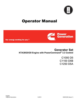
  • 1. Operator Manual Generator Set KTA38G5/G9 Engine with PowerCommand® 3.3 Control C1000 D5 C1100 D5B C1250 D5A English 5-2012 A042V240 (Issue 1) Original Instructions
  • 2.
  • 3. Table of Contents 1. IMPORTANT SAFETY INSTRUCTIONS ....................................................................................... 1 1.1 Warning, Caution and Note Styles Used In This Manual ....................................................... 1 1.2 General Information ................................................................................................................ 1 1.2.1 General Safety Precautions......................................................................................... 1 1.3 Generator Set Safety Code .................................................................................................... 2 1.3.1 Moving Parts Can Cause Severe Personal Injury Or Death........................................ 3 1.3.2 Positioning of Generator Set....................................................................................... 3 1.3.3 Container Lifting – ISO 3874:1997 .............................................................................. 3 1.4 Electrical Shocks and Arc Flashes Can Cause Severe Personal Injury or Death.................. 4 1.4.1 NFPA Equivalent Standards ........................................................................................ 4 1.4.2 AC Supply and Isolation............................................................................................... 5 1.5 Fuel And Fumes Are Flammable............................................................................................ 5 1.5.1 Spillage ....................................................................................................................... 5 1.5.2 Fluid Containment....................................................................................................... 5 1.5.3 Do Not Operate in Flammable and Explosive Environments ...................................... 6 1.6 Exhaust Gases Are Deadly..................................................................................................... 6 1.6.1 Exhaust Precautions................................................................................................... 6 2. INTRODUCTION............................................................................................................................ 7 2.1 About This Manual.................................................................................................................. 7 2.2 Schedule of Abbreviations ...................................................................................................... 7 2.3 Related Literature ................................................................................................................... 8 2.4 After Sales Services................................................................................................................ 9 2.4.1 Maintenance................................................................................................................ 9 2.4.2 Warranty....................................................................................................................... 9 2.4.3 How to Obtain Service ............................................................................................... 10 3. SYSTEM OVERVIEW .................................................................................................................. 11 3.1 Generator Set Identification .................................................................................................. 11 3.1.1 Nameplate - Open Generator Set.............................................................................. 11 3.1.2 Nameplate - Enclosed Generator Set........................................................................ 12 3.2 Generator Set Components.................................................................................................. 12 3.3 Generator Set Rating............................................................................................................ 13 3.4 Engine................................................................................................................................... 13 3.4.1 Engine Data ............................................................................................................... 14 3.5 Sensors................................................................................................................................. 15 3.6 Normal Duty Air Cleaner....................................................................................................... 15 3.7 Pyrometers - Engine Exhaust............................................................................................... 15 3.8 Heaters ................................................................................................................................. 16 3.8.1 Heater Supply and Isolation...................................................................................... 16 3.9 Mains (Utility) Powered Battery Charger .............................................................................. 16 3.10 Alarm Module...................................................................................................................... 16 A042V240 (Issue 1) i
  • 4. Table of Contents 5-2012 3.11 System Options................................................................................................................... 17 3.11.1 Heavy Duty Air Cleaner ........................................................................................... 17 3.11.2 PowerCommand Universal Annunciator.................................................................. 17 3.11.3 Circuit Breaker ......................................................................................................... 18 4. CONTROL SYSTEM - POWERCOMMAND 3.3.......................................................................... 19 4.1 Control System Description .................................................................................................. 19 4.1.1 Control System Panel ................................................................................................ 19 4.1.2 Control System Panel ................................................................................................ 20 4.1.3 Operating Modes........................................................................................................ 20 4.1.4 Power On and Sleep Modes...................................................................................... 22 4.2 Operator Panel...................................................................................................................... 23 4.2.1 Selection Buttons ....................................................................................................... 25 4.2.2 Default Settings.......................................................................................................... 25 4.2.3 Lamp Indicators.......................................................................................................... 25 4.2.4 Lamp (LED) Test Button ............................................................................................ 26 4.2.5 Reset Button .............................................................................................................. 26 4.2.6 CB (Circuit Breaker) Open Button ............................................................................. 26 4.2.7 CB (Circuit Breaker) Closed Button ........................................................................... 26 4.2.8 Graphical Display and Buttons................................................................................... 26 4.3 Operator Panel - Initial Operator Menu ................................................................................ 29 4.3.1 Initial Menu Data........................................................................................................ 29 4.4 Operator Panel - Generator Set Data Operator Menu.......................................................... 31 4.4.1 Generator Set Data.................................................................................................... 31 4.5 Operator Panel - Engine Data Operator Menu..................................................................... 33 4.5.1 Engine Data ............................................................................................................... 33 4.5.2 History/About Menu.................................................................................................... 35 4.6 Operator Panel - Alternator Data Operator Menu................................................................. 37 4.6.1 Alternator Data........................................................................................................... 37 4.7 Operator Panel - Faults and Warnings Menus ..................................................................... 38 4.7.1 Shutdown Fault Menu................................................................................................ 38 4.7.2 Fault Messages.......................................................................................................... 40 4.7.3 Fault Acknowledgement............................................................................................. 40 4.7.4 Warning Fault Menu................................................................................................... 40 4.7.5 Faults History Data Operator Menu ........................................................................... 41 4.8 Operator Panel - Adjust Menu .............................................................................................. 43 4.9 Operator Panel - Genset Setup Data Operator Menu .......................................................... 45 4.10 Operator Panel - Paralleling Status Menu .......................................................................... 46 4.11 Operator Panel - Paralleling/Basic Setup Menu ................................................................. 49 4.12 Selecting Operating Modes................................................................................................. 53 4.12.1 Mode Change Access.............................................................................................. 53 4.12.2 Selecting Manual Run Mode.................................................................................... 54 4.12.3 Selecting Auto Mode................................................................................................ 54 4.12.4 Selecting Off Mode .................................................................................................. 55 5. OPERATION - POWERCOMMAND 3.3 ...................................................................................... 57 5.1 Safety.................................................................................................................................... 57 ii A042V240 (Issue 1)
  • 5. 5-2012 Table of Contents 5.2 Introduction ........................................................................................................................... 57 5.3 Maintenance ......................................................................................................................... 58 5.4 Operating Recommendations ............................................................................................... 58 5.4.1 Running-in.................................................................................................................. 58 5.4.2 No Load Operation.................................................................................................... 58 5.4.3 Exercise Period.......................................................................................................... 58 5.4.4 Low Operating Temperatures .................................................................................... 58 5.4.5 High Operating Temperatures ................................................................................... 58 5.4.6 Operating Conditions for Prime, Standby and Continuous Power Ratings .............. 59 5.4.7 De-Rating Factors..................................................................................................... 60 5.5 Generator Set Operation....................................................................................................... 60 5.5.1 Sequence of Operation.............................................................................................. 62 5.6 Starting.................................................................................................................................. 62 5.6.1 Initial Pre-start Checks.............................................................................................. 63 5.6.2 Operator’s Pre-start Checks ...................................................................................... 64 5.6.3 Starting at Operator Panel (Manual Run Mode) ........................................................ 64 5.6.4 Starting from Remote Location (Auto Mode) ............................................................. 65 5.6.5 Cold Starting with Loads........................................................................................... 65 5.7 Stopping................................................................................................................................ 66 5.7.1 Stopping at Operator Panel (Manual Mode).............................................................. 66 5.7.2 Stopping from Operator Panel (Auto Mode) .............................................................. 67 5.7.3 Stopping from Remote Location (Auto Mode) .......................................................... 67 5.7.4 Emergency Stop (Code 1433 or 1434)..................................................................... 67 5.8 Paralleling Operation ............................................................................................................ 68 5.8.1 Speed and Voltage Matching..................................................................................... 68 5.8.2 Operation When in Parallel ....................................................................................... 68 5.8.3 Generator Set Application Type................................................................................. 69 5.8.4 Standalone Application .............................................................................................. 70 5.8.5 Synchronize Only....................................................................................................... 70 5.8.6 Isolated Bus Only....................................................................................................... 71 5.8.7 Power Transfer Control (Option)................................................................................ 72 5.8.8 Conditions for Each Paralleling State ........................................................................ 77 6. MAINTENANCE ........................................................................................................................... 87 6.1 Locking the Generator Set Out of Service............................................................................ 88 6.1.1 Immobilizing for Safe Working ................................................................................... 88 6.2 Periodic Maintenance ........................................................................................................... 89 6.2.1 Periodic Maintenance Schedule ................................................................................ 89 6.3 Daily or Refueling Maintenance Procedures ........................................................................ 92 6.3.1 General Information ................................................................................................... 92 6.3.2 Engine Operation Report .......................................................................................... 92 6.4 Cooling System..................................................................................................................... 93 6.4.1 Coolant Level - Check .............................................................................................. 93 6.4.2 Cooling Fan - Inspection............................................................................................ 94 6.4.3 Drive Belt - Inspection................................................................................................ 95 6.4.4 Radiator - Check........................................................................................................ 96 A042V240 (Issue 1) iii
  • 6. Table of Contents 5-2012 6.5 Engine Oil – Level Check ..................................................................................................... 96 6.6 Fuel System.......................................................................................................................... 97 6.6.1 Fuel Level ................................................................................................................. 98 6.6.2 Fuel/Water Separator - Drain.................................................................................... 98 6.7 Fluid Containment................................................................................................................. 98 6.7.1 Spillage ..................................................................................................................... 99 6.7.2 Fluid Containment..................................................................................................... 99 6.8 Hoses and Fuel Lines - Check ........................................................................................... 100 6.9 Air Intake System................................................................................................................ 100 6.9.1 Air Cleaner Service Indicator ................................................................................... 100 6.9.2 Normal Duty Air Cleaner.......................................................................................... 101 6.9.3 Heavy Duty Air Cleaner ........................................................................................... 102 6.10 Exhaust System................................................................................................................ 104 6.11 Generator Set Output - AC Electric System ..................................................................... 104 6.12 DC Electrical System ........................................................................................................ 104 6.13 Lead Acid Batteries........................................................................................................... 105 6.13.1 Storage................................................................................................................... 105 6.13.2 Safety Precautions................................................................................................. 105 6.13.3 Battery Maintenance .............................................................................................. 106 6.13.4 Electrolyte - Specific Gravity and Temperature ..................................................... 108 6.13.5 Battery Replacement.............................................................................................. 109 6.13.6 Electrolyte Levels and Bench Charging Rates ...................................................... 109 6.13.7 Battery Fault Finding.............................................................................................. 111 7. TROUBLESHOOTING ............................................................................................................... 113 7.1 Control System ................................................................................................................... 113 7.2 Safety Considerations......................................................................................................... 113 7.3 Fault Finding ....................................................................................................................... 114 7.4 Status Indicators - PowerCommand 3.3............................................................................. 114 7.4.1 Not in Auto .............................................................................................................. 115 7.4.2 Remote Start ........................................................................................................... 115 7.4.3 Warning ................................................................................................................... 115 7.4.4 Shutdown Status ..................................................................................................... 115 7.4.5 Generator Set Running ........................................................................................... 115 7.5 Fault/Status Codes - PowerCommand 3.3 ......................................................................... 115 7.5.1 Fault Messages........................................................................................................ 115 7.5.2 Fault Acknowledgement........................................................................................... 115 7.5.3 Fault Codes - PowerCommand 3 .3 ........................................................................ 116 7.5.4 Customer Input Faults.............................................................................................. 127 7.6 Line Circuit Breaker ............................................................................................................ 132 8. BATTERY CHARGER................................................................................................................ 133 8.1 Mains (Utility) Powered Battery Charger - Wall-Mounted (Option)..................................... 133 8.1.1 Boost........................................................................................................................ 133 8.1.2 Specifications - 5 Amp and 10 Amp......................................................................... 134 8.2 Mains (Utility) Powered Battery Charger – Set Mounted.................................................... 134 8.2.1 Specifications - 5 Amp ............................................................................................. 135 iv A042V240 (Issue 1)
  • 7. 5-2012 Table of Contents 8.3 Circuits................................................................................................................................ 135 9. MANUFACTURING FACILITIES................................................................................................ 137 9.1 How to Obtain Service........................................................................................................ 137 A042V240 (Issue 1) v
  • 8. Table of Contents 5-2012 This page is intentionally blank. vi A042V240 (Issue 1)
  • 9. 1 Important Safety Instructions SAVE THESE INSTRUCTIONS - This manual contains important instructions that should be followed during installation and maintenance of the generator set and batteries. Safe and efficient operation can be achieved only if the equipment is properly operated and maintained. Many accidents are caused by failure to follow fundamental rules and precautions. 1.1 Warning, Caution and Note Styles Used In This Manual The following safety styles and symbols found throughout this manual indicate potentially hazardous conditions to the operator, service personnel or the equipment. DANGER: Warns of a hazard that will result in severe personal injury or death . WARNING: Warns of a hazard that may result in severe personal injury or death . CAUTION: Warns of a hazard or an unsafe practice that can result in product or property damage . NOTE: A short piece of text giving information that augments the current text . 1.2 General Information This manual should form part of the documentation package supplied by Cummins Power Generation with specific generator sets. In the event that this manual has been supplied in isolation please contact your authorized distributor. NOTE: It is in the Operator’s interest to read and understand all Warnings and Cautions contained within the documentation relevant to the generator set, its operation and daily maintenance . 1.2.1 General Safety Precautions WARNING: Coolants under pressure can cause severe scalding. Do not open a radiator or heat exchanger pressure cap while the engine is running. Let the engine cool down before removing the coolant pressure cap. Turn the cap slowly and do not open it fully until the pressure has been relieved. WARNING: Moving parts can cause severe personal injury or death and hot exhaust parts can cause severe burns. Make sure all protective guards are properly in place before starting the generator set. WARNING: Used engine oils have been identified by some state and federal agencies to cause cancer or reproductive toxicity. Do not ingest, breathe the fumes, or contact used oil when checking or changing engine oil. WARNING: Operation of equipment is unsafe when mentally or physically fatigued. Do not operate equipment in this condition, or after consuming any alcohol or drug. A042V240 (Issue 1) 1
  • 10. 1. Important Safety Instructions 5-2012 WARNING: Substances in exhaust gases have been identified by some state and federal agencies to cause cancer or reproductive toxicity. Do not breath in or come into contact with exhaust gases. WARNING: Flammable liquids can cause fire or explosion. Do not store fuel, cleaners, oil, etc. near the generator set. WARNING: Wear hearing protection when going near an operating generator set . WARNING: Hot metal parts can cause severe burns. Avoid contact with the radiator, turbo charger, and exhaust system. WARNING: Maintaining or installing a generator set can cause severe personal injury. Wear personal protective equipment such as safety glasses, protective gloves, hard hats, steel-toed boots, and protective clothing when working on equipment. WARNING: Ethylene glycol, used as engine coolant, is toxic to humans and animals. Clean up coolant spills and dispose of used antifreeze in accordance with local environmental regulations. WARNING: Starting fluids, such as ether, can cause explosion and generator set engine damage. Do not use. CAUTION: Do not step on the generator set when entering or leaving the generator room. Parts can bend or break leading to electrical shorts, or to fuel, coolant, or exhaust leaks. CAUTION: To prevent accidental or remote starting while working on the generator set, disconnect the negative (-) battery cable at the battery using an insulated wrench. CAUTION: Make sure that rags are not left on or near the engine. CAUTION: Make sure the generator set is mounted in a manner to prevent combustible materials from accumulating under the unit . CAUTION: Accumulated grease and oil can cause overheating and engine damage presenting a potential fire hazard. Keep the generator set clean and repair any oil leaks promptly. CAUTION: Before performing maintenance and service procedures on enclosed generator sets, make sure the service access doors are secured open. CAUTION: Keep the generator set and the surrounding area clean and free from obstructions. Remove any debris from the set and keep the floor clean and dry. NOTE: Keep multi-class ABC fire extinguishers handy. Class A fires involve ordinary combustible materials such as wood and cloth. Class B fires involve combustible and flammable liquid fuels and gaseous fuels. Class C fires involve live electrical equipment. (Refer to NFPA No. 10 in applicable region.) 1.3 Generator Set Safety Code Before operating the generator set, read the manuals and become familiar with them and the equipment. Safe and efficient operation can be achieved only if the equipment is properly operated and maintained. Many accidents are caused by failure to follow fundamental rules and precautions. 2 A042V240 (Issue 1)
  • 11. 5-2012 1. Important Safety Instructions WARNING: Improper operation and maintenance can lead to severe personal injury or loss of life and property by fire, electrocution, mechanical breakdown, or exhaust gas asphyxiation. Read and follow all Safety Precautions, Warnings and Cautions throughout this manual and the documentation supplied with your generator set . WARNING: Lifting and repositioning of the generator set must only be carried out using suitable lifting equipment, shackles, and spreader bars, in accordance with local guidelines and legislation, by suitably trained and experienced personnel. Incorrect lifting can result in severe personal injury, death and/or equipment damage. For more information, contact your authorized distributor . 1.3.1 Moving Parts Can Cause Severe Personal Injury Or Death · Keep your hands, clothing, and jewelry away from moving parts. · Before starting work on the generator set, disconnect the battery charger from its AC source, then disconnect the starting batteries using an insulated wrench, negative (–) cable first. This will prevent accidental starting. · Make sure that fasteners on the generator set are secure. Tighten supports and clamps; keep guards in position over fans, drive belts, etc. · Do not wear loose clothing or jewelry in the vicinity of moving parts or while working on electrical equipment. Loose clothing and jewelry can become caught in moving parts. · If any adjustments must be made while the unit is running, use extreme caution around hot manifolds, moving parts, etc. 1.3.2 Positioning of Generator Set The area for positioning the set should be adequate and level and the area immediately around the set must be free of any flammable material. WARNING: On an enclosed generator set, the canopy doors must be locked before re- positioning and they must remain locked during transportation and sitting . 1.3.3 Container Lifting – ISO 3874:1997 Lifting should be carried out using the ISO container lifting blocks in either the top or bottom of the container using methods defined in ISO 3874:1997. 1.3.3.1 Lifting using a Fork Lift If a forklift is to be used to move the containerized generator set, the forks must be inserted under the base of the container. The forklift pockets must only be used to lift an empty container. Refer to the General Arrangement drawings for further reference information including the Centre of Gravity. A042V240 (Issue 1) 3
  • 12. 1. Important Safety Instructions 5-2012 1.4 Electrical Shocks and Arc Flashes Can Cause Severe Personal Injury or Death WARNING: Any work with exposed energized circuits with potentials of 50 Volts AC or 75 Volts DC or higher poses a significant risk of electrical shock and electrical arc flash. These silent hazards can cause severe injuries or death. Refer to standard NFPA 70E or equivalent safety standards in corresponding regions for details of the dangers involved and for the safety requirements. Guidelines to follow when working on de-energized electrical systems: · Use proper PPE. Do not wear jewelry and make sure that any conductive items are removed from pockets as these items can fall into equipment and the resulting short circuit can cause shock or burning. Refer to standard NFPA 70E for PPE standards. · De-energize and lockout/tagout electrical systems prior to working on them. Lockout/Tagout is intended to prevent injury due to unexpected start-up of equipment or the release of stored energy. Please refer to the lockout/tagout section for more information. · De-energize and lockout/tagout all circuits and devices before removing any protective shields or making any measurements on electrical equipment. · Follow all applicable regional electrical and safety codes. Guidelines to follow when working on energized electrical systems: NOTE: It is the policy of Cummins Inc. to perform all electrical work in a de- energized state. However, employees or suppliers may be permitted to occasionally perform work on energized electrical equipment only when qualified and authorized to do so and when troubleshooting, or if de- energizing the equipment would create a greater risk or make the task impossible and all other alternatives have been exhausted. NOTE: Exposed energized electrical work is only allowed as per the relevant procedures and must be undertaken by a Cummins authorized person with any appropriate energized work permit for the work to be performed while using proper PPE, tools and equipment. In summary: · · Do not tamper with or bypass interlocks unless you are authorized to do so. · · Understand and assess the risks - use proper PPE. Do not wear jewelry and make sure that any conductive items are removed from pockets as these items can fall into equipment and the resulting short circuit can cause shock or burning. Refer to standard NFPA 70E for PPE standards. · · Make sure that an accompanying person who can undertake a rescue is nearby. 1.4.1 NFPA Equivalent Standards BS EN 12601:2010 Reciprocating internal combustion engine driven generating sets — Safety. International Relationships EN 12601:2010 Identical BS EN 60204-1:2006+A1:2009 Safety of machinery. Electrical equipment of machines. General requirements. International Relationships EN 60204-1:2006 Identical, IEC 60204-1:2005 Modified. 4 A042V240 (Issue 1)
  • 13. 5-2012 1. Important Safety Instructions 1.4.2 AC Supply and Isolation It is the sole responsibility of the customer to provide AC power conductors for connection to load devices and the means to isolate the AC input to the terminal box; these must comply to local electrical codes and regulations. Refer to the wiring diagram supplied with the generator set. NOTE: Local electrical codes and regulations (for example BS EN 12601:2001) may require the installation of a disconnect means for the generator set, either on the generator set or where the generator set conductors enter a facility . NOTE: The AC supply must have the correct over current and earth fault protection according to local electrical codes and regulations. This equipment must be earthed (grounded) . The disconnecting device is not provided as part of the generator set, and Cummins Power Generation accepts no responsibility for providing the means of isolation. 1.5 Fuel And Fumes Are Flammable Fire, explosion, and personal injury or death can result from improper practices. · DO NOT fill fuel tanks while the engine is running, unless the tanks are outside the engine compartment. Fuel contact with hot engine or exhaust is a potential fire hazard. · DO NOT permit any flame, cigarette, pilot light, spark, arcing equipment, or other ignition source near the generator set or fuel tank. · Fuel lines must be adequately secured and free of leaks. Fuel connection at the engine should be made with an approved flexible line. Do not use copper piping on flexible lines as copper will become brittle if continuously vibrated or repeatedly bent. · Be sure all fuel supplies have a positive shutoff valve. · Be sure the battery area has been well-ventilated prior to servicing near it. Lead-acid batteries emit a highly explosive hydrogen gas that can be ignited by arcing, sparking, smoking, etc. 1.5.1 Spillage Any spillage that occurs during fueling or during oil top-off or oil change must be cleaned up before starting the generator set. 1.5.2 Fluid Containment If fluid containment is incorporated into the bedframe, it must be inspected at regular intervals. Any liquid present should be drained out and disposed of in line with local health and safety regulations. Failure to perform this action may result in spillage of liquids which could contaminate the surrounding area. Any other fluid containment area must also be checked and emptied, as described above. NOTE: Where spillage containment is not part of a Cummins supply, it is the responsibility of the installer to provide the necessary containment to prevent contamination of the environment, especially water courses/sources . A042V240 (Issue 1) 5
  • 14. 1. Important Safety Instructions 5-2012 1.5.3 Do Not Operate in Flammable and Explosive Environments Flammable vapor can cause an engine to overspeed and become difficult to stop, resulting in possible fire, explosion, severe personal injury and death. Do not operate a generator set where a flammable vapor environment can be created by fuel spill, leak, etc., unless the generator set is equipped with an automatic safety device to block the air intake and stop the engine. The owners and operators of the generator set are solely responsible for operating the generator set safely. Contact your authorized Cummins Power Generation distributor for more information. 1.6 Exhaust Gases Are Deadly · Provide an adequate exhaust system to properly expel discharged gases away from enclosed or sheltered areas and areas where individuals are likely to congregate. Visually and audibly inspect the exhaust daily for leaks per the maintenance schedule. Make sure that exhaust manifolds are secured and not warped. Do not use exhaust gases to heat a compartment. · Be sure the unit is well ventilated. WARNING: Engine exhaust and some of its constituents are known to the state of California to cause cancer, birth defects, and other reproductive harm . 1.6.1 Exhaust Precautions WARNING: Exhaust pipes and charge air pipes are very hot and they can cause severe personal injury or death from direct contact or from fire hazard . WARNING: Hot exhaust gas can cause burns resulting in severe personal injury . The exhaust outlet may be sited at the top or bottom of the generator set. Make sure that the exhaust outlet is not obstructed. Personnel using this equipment must be made aware of the exhaust position. Position the exhaust away from flammable materials - in the case of exhaust outlets at the bottom, make sure that vegetation is removed from the vicinity of the exhaust. WARNING: Inhalation of exhaust gases can result in serious personal injury or death. Be sure deadly exhaust gas is piped outside and away from windows, doors, or other inlets to buildings. Do not allow to accumulate in habitable areas . WARNING: Contaminated insulation is a fire risk which can result in severe personal injury . The exhaust pipes may have some insulating covers fitted. If these covers become contaminated by fuel or oil, they must be replaced before the generator set is run. To minimize the risk of fire, make sure the following steps are observed: · Make sure that the engine is allowed to cool thoroughly before topping off the oil or draining the fuel filters. · Clean the exhaust pipe thoroughly. 6 A042V240 (Issue 1)
  • 15. 2 Introduction 2.1 About This Manual The purpose of this manual is to provide the users with sound, general information. It is for guidance and assistance with recommendations for correct and safe procedures. Cummins Power Generation (CPG) cannot accept any liability whatsoever for problems arising as a result of following recommendations in this manual. The information contained within the manual is based on information available at the time of going to print. In line with Cummins Power Generation policy of continuous development and improvement, information may change at any time without notice. The users should therefore make sure that before commencing any work, they have the latest information available. Users are respectfully advised that, in the interests of good practice and safety, it is their responsibility to employ competent persons to carry out any installation work. Consult your authorized distributor for further installation information. It is essential that the utmost care is taken with the application, installation, and operation of any engine due to their potentially hazardous nature. Careful reference should also be made to other Cummins Power Generation literature. A generator set must be operated and maintained properly if you are to expect safe and reliable operation. Should you require further assistance, contact your authorized distributor. 2.2 Schedule of Abbreviations This list is not exhaustive. For example, it does not identify units of measure or acronyms that appear only in parameters, event/fault names, or part/accessory names. AmpSentry and InPower are trademarks of Cummins Inc. PowerCommand is a registered trademark of Cummins Inc. ACRONYM DESCRIPTION ACRONYM DESCRIPTION AC Alternating Current LED Light-emitting Diode AMP AMP, Inc., part of Tyco Electronics Mil Std Military Standard ASTM American Society for Testing and MMHG Millimeters of Mercury Materials (ASTM International) ATS Automatic Transfer Switch NC Not Connected AVR Automatic Voltage Regulator NC Normally Closed AWG American Wire Gauge NFPA National Fire Protection Agency CAN Controlled Area Network NO Normally Open CB Circuit Breaker NWF Network Failure CE Conformité Européenne OEM Original Equipment Manufacturer CFM Cubic Feet per Minute OOR Out of Range CGT Cummins Generator Technologies OORH / ORH Out of Range High CMM Cubic Meters per Minute OORL / ORL Out of Range Low CT Current Transformer PSI Pounds per square inch A042V240 (Issue 1) 7
  • 16. 2. Introduction 5-2012 ACRONYM DESCRIPTION ACRONYM DESCRIPTION DC Direct Current PB Push Button ECM Engine Control Module PC Personal Computer ECS Engine Control System PCC PowerCommand® Control EMI Electromagnetic interference PGI Power Generation Interface EN European Standard PGN Parameter Group Number EPS Engine Protection System PI Proportional/Integral E-Stop Emergency Stop PID Proportional/Integral/Derivative FAE Full Authority Electronic PLC Programmable Logic Controller FMI Failure Mode Identifier PMG Permanent Magnet Generator FSO Fuel Shutoff PT Potential Transformer Genset Generator Set PTC Power Transfer Control GCP Generator Control Panel PWM Pulse-width Modulation GND Ground RFI Radio Frequency Interference HMI Human-machine Interface RH Relative Humidity IC Integrated Circuit RMS Root Mean Square INHG Inches of Mercury RTU Remote Terminal Unit ISO International Organization for SAE Society of Automotive Engineers Standardization kPA kilo-Pascal SPN Suspect Parameter Number LBNG Lean-burn Natural Gas SW_B+ Switched B+ LCD Liquid Crystal Display UL Underwriters Laboratories LCL Low Coolant Level UPS Uninterruptible Power Supply LCT Low Coolant Temperature 2.3 Related Literature Before any attempt is made to operate the generator set, the operator should take time to read all of the manuals supplied with the generator set, and to familiarize themselves with the warnings and operating procedures. CAUTION: A generator set must be operated and maintained properly if you are to expect safe and reliable operation. The Operator manual includes a maintenance schedule and a troubleshooting guide. The Health and Safety manual must be read in conjunction with this manual for the safe operation of the generator set: · Health and Safety Manual (0908-0110) The relevant manuals appropriate to your generator set are also available, the documents below are in English: · Operator Manual for KTA38G5/G9 with PowerCommand 3.3 Control (A042V240) · Installation Manual for KTA38G5/G9 with PowerCommand 3.3 Control (A042V241) 8 A042V240 (Issue 1)
  • 17. 5-2012 2. Introduction · Generator Set Service Manual for KTA38G5/G9 with PowerCommand 3.3 Control (A042V242) · Controller Service Manual for PowerCommand 3.3 Control (0900-0670) · Engine Operation & Maintenance Manual for KTA38 (3810497) · Alternator Service Manual for HC Alternators (0900-9904,A040J849) · Alternator Service Manual for P7 Alternators (0900-9902,A040J850) · Specification and Data Sheet (For engineering data specific to the generator set) · Application Manual T-030, Liquid Cooled Generator Sets (For application information) · Parts Manual for KTA38 G5 (A042T993) · Parts Manual for KTA38 G9 (A042W603) · Standard Repair Times - CL Family (0900-0913) · Recommended Spares List (RSL) for C1000 D5 (A042W934) · Recommended Spares List (RSL) for C1100 D5B (A042W935) · Recommended Spares List (RSL) for C1250 D5A (A042W936) · Warranty Manual (F1117) · Global Commercial Warranty Statement (A028U870) Contact your authorized distributor for more information regarding related literature for this product. 2.4 After Sales Services Cummins Power Generation offer a full range of maintenance and warranty services. 2.4.1 Maintenance WARNING: Incorrect service or parts replacement can result in severe personal injury, death, and/or equipment damage. Service personnel must be trained and experienced to perform electrical and/or mechanical service. For customers who wish to have their generator sets expertly serviced at regular intervals your local distributor offers a complete maintenance contract package. This covers all items subject to routine maintenance and includes a detailed report on the condition of the generator set. In addition, this can be linked to a 24-hour call-out arrangement, providing year-round assistance if necessary. Specialist engineers are available to maintain optimum performance levels from customer’s generator sets, and it is recommended that maintenance tasks are only undertaken by trained and experienced technicians provided by your authorized distributor. 2.4.2 Warranty For details of the warranty coverage for your generator set, refer to the Global Commercial Warranty Statement (A028U870). Extended warranty coverage is also available. In the event of a breakdown, prompt assistance can normally be given by factory trained service technicians with facilities to undertake all minor and many major repairs to equipment on site. A042V240 (Issue 1) 9
  • 18. 2. Introduction 5-2012 For further warranty details, contact your authorized distributor. NOTE: Damage caused by failure to follow the correct coolant recommendations will not be covered by the warranty. Please contact your authorized distributor. 2.4.2.1 Warranty Limitations For details of the warranty limitations for your generator set, refer to the warranty statement applicable to the generator set. 2.4.3 How to Obtain Service When a product requires servicing, contact your nearest Cummins Power Generation distributor. To locate your local Cummins Power Generation distributor, refer to www.cumminspower.com and select Distributor Locator. When contacting your distributor, always supply the complete Model, Specification, and Serial Number as shown on the nameplate. 10 A042V240 (Issue 1)
  • 19. 3 System Overview This section provides an overview of the Generator Set. 3.1 Generator Set Identification Each generator set is provided with a nameplate similar to that shown below. This provides information unique to each generator set. 3.1.1 Nameplate - Open Generator Set FIGURE 1. TYPICAL OPEN GENERATOR SET NAMEPLATE A042V240 (Issue 1) 11
  • 20. 3. System Overview 5-2012 3.1.2 Nameplate - Enclosed Generator Set FIGURE 2. TYPICAL ENCLOSED GENERATOR SET NAMEPLATE 3.2 Generator Set Components The main components of a typical KTA38 engine generator set are shown below, and referred to within this section. There are various options listed although they may not be available for all models. 12 A042V240 (Issue 1)
  • 21. 5-2012 3. System Overview No Description No Description 1 Radiator (Not indicated) 2 Engine Battery and Tray 3 Controller Alarm Module 4 Battery Battery Charger 5 Alternator Engine Coolant Heater 6 Bed Frame Alternator Heater FIGURE 3. TYPICAL KTA38 ENGINE GENERATOR SET 3.3 Generator Set Rating For details of your generator set rating, refer to the Generator Set nameplate. Refer to Section 5.4 on page 58 for operation at temperatures or altitudes above those stated on the nameplate. 3.4 Engine For additional engine specific information, refer to the relevant engine manual for your generator set. A042V240 (Issue 1) 13
  • 22. 3. System Overview 5-2012 No. Description 1 Oil filler cap 2 Fan belt 3 Dipstick FIGURE 4. TYPICAL ENGINE COMPONENTS (KTA38) 3.4.1 Engine Data 3.4.1.1 Acoustic Information 3.4.1.1.1 Acoustic Information (1500 rpm) TABLE 1. ACOUSTIC DATA (1500 RPM) Model C1000 D5 C1100 D5B C1250 D5A Engine KTA38G5 KTA38G5 KTA38G9 Enclosed Set Acoustic Data – LWA 105 105 105 (Based on using a standard Cummins’ canopy, and 50 Hz set operating with doors closed) 1, 2 Open Set Acoustic Data – dB(A) at 1m 98.3 98.3 101.3 3 – SPL (or enclosed set with doors open) 1. Doors closed figures are measured using 2000/14/EC guaranteed sound power levels 2. Based on 75% load 3. Doors closed figures are measured using 2000/14/EC guaranteed sound power levels For Noise Spectrum Figures, refer also to your authorised distributor. In line with the Cummins Power Generation policy of continuous improvement, these figures are subject to change. 14 A042V240 (Issue 1)
  • 23. 5-2012 3. System Overview 3.4.1.2 Engine Fuel Consumption (L/hr) Model C1000 D5 C1100 D5B C1250 D5A Engine KTA38G5 KTA38G5 KTA38G9 Engine Performance Data at 50Hz1 228 (50.1) 228 (50.1) 306 (67.3) 1. Standby/Full Load Refer to Data Sheets for other applications. In line with the CPG policy of continuous improvement these figures are subject to change. 3.5 Sensors Various generator set parameters are measured by sensors, and the resulting signals are processed by the control board. Engine-mounted sensors monitor a number of different systems, including: · Lube Oil Pressure · Cooling System Temperature 3.6 Normal Duty Air Cleaner The standard air cleaner assembly includes two air cleaner cannisters. FIGURE 5. NORMAL AIR CLEANER ASSEMBLY 3.7 Pyrometers - Engine Exhaust A pyrometer measures engine exhaust gas temperature. A separate temperature meter is used to monitor each exhaust outlet elbow. A042V240 (Issue 1) 15
  • 24. 3. System Overview 5-2012 3.8 Heaters CAUTION: Energizing heater(s) when the coolant system has been drained or if there is a suspicion that the coolant is frozen can result in equipment damage. Always make sure the radiator is filled to the recommended level before energizing the heater(s). 3.8.1 Heater Supply and Isolation A heater supply is required for the operation of the engine and alternator heaters (if fitted). NOTE: It is the sole responsibility of the customer to provide the power supply and the means to isolate the AC input to the terminal box. Cummins Power Generation accepts no responsibility for providing the means of isolation. NOTE: This disconnecting device is not provided as part of the generator set. 3.9 Mains (Utility) Powered Battery Charger This unit maintains the battery in a fully charged condition without over-charging. The unit also provides rapid charging, when necessary, at a current up to the rated output. The charger’s electronic control circuit allows the charger to be left in circuit during engine cranking and to operate in parallel with the charge alternator. The charger will supply current to the battery system until the battery terminal voltage becomes equal to the set float voltage, at which point only a trickle charge current is present. When the battery becomes discharged due to a load being present and the terminal voltage falls, the charger will again supply current to restore the voltage of the battery to the float voltage. CAUTION: Disconnect the battery charger before isolating the battery. Failure to do so can result in voltage spikes high enough to cause equipment damage and personal injury. There are two types of battery charger that are provided: · Set-Mounted · Wall-Mounted For more information on Battery Chargers see Chapter 8 on page 133. 3.10 Alarm Module The Alarm Module provides audible warnings. A rocker switch provides the means to switch the alarm facility on or off. 16 A042V240 (Issue 1)
  • 25. 5-2012 3. System Overview FIGURE 6. ALARM MODULES FRONT PANEL 3.11 System Options 3.11.1 Heavy Duty Air Cleaner The heavy duty air cleaner assembly is used in dusty environments. The air cleaner includes of a primary and a safety element. The rubber breather tube on the bottom of each filter canister should be checked periodically to make sure it is free of dust an dirt. FIGURE 7. HEAVY DUTY AIR CLEANER ASSEMBLY 3.11.2 PowerCommand Universal Annunciator A universal annunciator provides lamps and a horn to annunciate the operating status and fault conditions of an emergency power system. It is designed for connection to either a 12 VDC or a 24 VDC control system. It can be configured to be either a positive or negative signal device. Two versions of the PowerCommand universal annunciator are available. · Panel Mounted A042V240 (Issue 1) 17
  • 26. 3. System Overview 5-2012 · Panel with Enclosure The universal annunciator can communicate using either a PCCNet or a Modbus network. Refer to the annunciator owner's manual for more information. No. Description No Description 1 System Status Lamps 4 Silence/Lamp Test Button 2 Insert Card 5 Network Status Lamp 3 Horn FIGURE 8. ANNUNCIATOR COMPONENTS 3.11.3 Circuit Breaker A circuit breaker is used to prevent the generator from being overloaded. A line circuit breaker is mounted in the generator output box. If the load exceeds the circuit breaker current rating, the line circuit breaker will open, preventing the generator from being overloaded. If the circuit breaker trips, locate the source of the overload and correct as necessary. Manually reset the breaker to reconnect the load to the generator. 18 A042V240 (Issue 1)
  • 27. 4 Control System - PowerCommand 3.3 4.1 Control System Description The control system is used to start and stop the generator set from the display screen in either Manual or Auto mode. It is suitable for stand alone or paralleling generator sets in both standby and prime-power applications, providing full generator set monitoring capability and protection. It monitors the engine for temperature, oil pressure and speed, and provides voltage and current metering. In the event of a fault the unit indicates the fault type and automatically shuts down the generator set on critical faults. All indicators, control buttons and the display screen are on the face of the operator panel as illustrated in the following figure. There are two fault level signals generated by the control system as follows: · Warning: signals an imminent or non-critical fault for the engine. The control provides an indication only for this condition. · Shutdown: signals a potentially critical fault for the engine. The control immediately takes the engine off-load and automatically shuts it down. The standard control system operates on 12 or 24 VDC battery power. The auxiliary equipment operates on LV AC power. The history data is stored in non-volatile memory and is not deleted if battery power is lost. 4.1.1 Control System Panel 1 Operator Panel 2 Alarm Module (option) 3 Emergency Stop Button FIGURE 9. TYPICAL CONTROL SYSTEM PANEL (HMI 330) A042V240 (Issue 1) 19
  • 28. 4. Control System - PowerCommand 3.3 5-2012 4.1.2 Control System Panel No. Description No. Description 1 Bargraph Meter Panel (option) 4 Emergency Stop Button 2 Operator Panel 5 Alarm Module (option) 3 Temperature Meters FIGURE 10. CONTROL SYSTEM PANEL 4.1.3 Operating Modes The PowerCommand® 3.3 control is operated by the Start/Stop/Manual/Auto buttons on the Operator Panel. Refer to Figure 11 on page 24. NOTE: If the Mode Change access feature is enabled, a password is required to use these buttons to change the mode of operation. Contact your authorized distributor for options. 4.1.3.1 Stop Button 20 A042V240 (Issue 1)
  • 29. 5-2012 4. Control System - PowerCommand 3.3 Press this button to put the generator set into the Off mode. This disables Auto and Manual modes. The green lamp above this button lights when the generator set is in the Off mode. If the generator set is running, in either Manual or Auto mode, and the Stop button is pressed, the engine shuts down. Refer to Section 4.12.4 on page 55 and Section 5.7 on page 66 for more information on stopping in Auto or Manual mode. NOTE: If possible, hot shutdown under load should be avoided to help prolong the reliability of the generator set. 4.1.3.2 Manual Button Press this button to put the generator set into the Manual mode. The Start button must then be pressed within ten seconds. Failure to do this results in the control mode defaulting, putting the generator set into the Off mode. The green lamp above this button is lit when the generator set is in Manual mode. NOTE: If Mode Change access code feature is enabled, the password must be entered before pressing the Start button. 4.1.3.3 Start Button When the Manual button is pressed, this Start button must be pressed within ten seconds to start the generator set. The generator set starts up normally but without the Time Delay to Start. In other modes, this button has no effect. NOTE: If the Start button is not pressed within the ten seconds of pressing the Manual button, the generator set mode changes to the Off mode automatically. 4.1.3.4 Auto Button Press this button to put the generator set into the Auto mode. In this mode, the generator set is controlled by a remote switch or device (e.g. transfer switch). The green lamp above this button lights when the generator set is in Auto mode. 4.1.3.5 Battle Short Mode Battle Short mode is not a distinct mode of operation. The PowerCommand® control is still in the Off, Manual, or Auto mode while Battle Short mode is active. The PowerCommand® control still follows the appropriate sequence of operation to start and stop the generator set. Battle Short mode is a generator set mode of operation that prevents the generator set from being shutdown by all but a few, select, critical shutdown faults. The purpose of Battle Short mode is to satisfy local code requirements, where necessary. To use this feature, the necessary software must be installed at the factory when the PowerCommand® control is purchased. Only authorized service personnel can enable this feature. When shipped from the factory, this feature is disabled. A042V240 (Issue 1) 21
  • 30. 4. Control System - PowerCommand 3.3 5-2012 NOTE: The Battle Short feature must be enabled or disabled using the InPower service tool. WARNING: Use of the Battle Short mode feature can cause a fire or electrical hazard, resulting in severe personal injury or death and/or property and equipment damage. Operation of the set must be supervised during Battle Short operation. This feature must only be used during supervised, temporary operation of the generator set. The faults that are overridden when in Battle Short mode can affect generator set performance, or cause permanent engine, alternator or connected equipment damage. CAUTION: If this mode of operation is selected, the protection of load devices will be disabled. Cummins Power Generation will not be responsible for any claim resulting from the use of this mode. CAUTION: All shutdown faults, including those overridden by Battle Short, must be acted upon immediately to ensure the safety and well being of the operator and the generator set. Battle Short is turned on or off with an external switch connected to one of the two customer configured inputs or a soft switch on the operator panel. When enabled, Battle Short switch input can be set using a Setup menu. To turn Battle Short mode on using the soft switch in the operator panel, Battle Short must be set to Operator Panel and enabled using the InPower service tool (default is Inactive). When Battle Short mode is enabled, the Warning status indicator lights and code 1131 – Battle Short Active – is displayed. When Battle Short mode is enabled and an overridden shutdown fault occurs, the shutdown lamp remains lit even though the set continues to run. Fault code 1416 – Fail to Shutdown – is displayed. If the fault is acknowledge, the fault message is cleared from the display but remains in the Fault History file as long as Battle Short mode is enabled. Battle Short is suspended and a shutdown occurs immediately if any of the following critical shutdown faults occur: · Speed Signal Lost (Loss of Speed Sense) - Fault code 121 · Overspeed - Fault code 234 · Local Emergency Stop - Fault code 1433 · Remote Emergency Stop - Fault code 1434 · Excitation Fault (Loss of Voltage Sense) - Fault code 2335 Or The Battle Short feature is disabled after an overridden shutdown fault occurred while in Battle Short mode. Fault code 1123 – Shutdown After Battle Short – is then displayed. 4.1.4 Power On and Sleep Modes The operating modes of the control panel and operating software are Power On and Sleep. Power On Mode In this mode, power is continuously supplied to the control panel. The control’s operating software and control panel lamps/graphical display remain active until the Sleep mode is activated. 22 A042V240 (Issue 1)
  • 31. 5-2012 4. Control System - PowerCommand 3.3 Sleep Mode Sleep mode is used to reduce battery power consumption when the control is not being used and it is in the Off or Auto mode. In this mode, the control’s operating software is inactive and the lamps and graphical display on the control panel are all off. When all conditions are met (i.e. no unacknowledged faults and the control is in the Off/Auto mode), the sleep mode activates after five minutes of keypad inactivity. This length of time is configurable. To activate the control and view the menu display without starting the generator set, press any control button. NOTE: Sleep mode can be enabled/disabled, contact your authorized distributor for options. 4.2 Operator Panel Figure 11 on page 24 shows the features of the front panel. It includes eight lamp indicators; the graphical display with nine buttons used to navigate through the menus; and six control mode buttons. This display panel enables the Operator to look at the status, adjust the settings, and start and stop the generator set. A042V240 (Issue 1) 23
  • 32. 4. Control System - PowerCommand 3.3 5-2012 1 Indicator Lamp – Warning 11 Stop Button 2 Indicator Lamp – Shutdown 12 Circuit Breaker – Close button 3 Indicator Lamp – Genset Running 13 Circuit Breaker – Open button 4 Indicator Lamp – Remote Start 14 Previous Menu Button 5 Indicator Lamp – Not in Auto 15 Four Change Selection Buttons (Up, Down, Left, Right) 6 Lamp Test Button 16 Item Select Button 7 Reset Button 17 Home Button 8 Manual Button 18 Four Soft-key Buttons (for use with Item 19) 9 Start Button 19 Graphical Display 10 Auto Mode Button FIGURE 11. OPERATOR PANEL 24 A042V240 (Issue 1)
  • 33. 5-2012 4. Control System - PowerCommand 3.3 4.2.1 Selection Buttons Four momentary buttons are used to navigate and change the selection in the graphical display. Press the OK button to select the item that is currently highlighted in the graphical display: · If the selected item is a menu item, this opens the sub-menu or screen. · If the selected item is a parameter, this lets you adjust the parameter (if possible) or prompts you for a password. · If the selected item is a value you have just adjusted, this saves the change. · If the selected item is an action, the graphical display runs the action or prompts you for a password. 4.2.2 Default Settings The Operator Panel can display SAE or Metric units of measurement and should be set during the initial setup of the generator set. Only trained and experienced personnel are allowed to change the default setting. Contact your authorized distributor. 4.2.3 Lamp Indicators Figure 11 on page 24 shows the front panel of the Operator Panel with the five lamp indicators. 4.2.3.1 Warning This amber lamp is lit whenever the control detects a Warning condition. This lamp is automatically shut off when the Warning condition no longer exists. 4.2.3.2 Shutdown Status This red lamp is lit when the control detects a Shutdown condition. The generator set cannot be started when this lamp is on. After the condition has been corrected, the lamp can be reset by first pressing the Stop button and then the Reset button. 4.2.3.3 Not in Auto This red lamp is lit when the control is NOT in Auto. 4.2.3.4 Remote Start This green lamp indicates the control is receiving a Remote Run signal. The Remote Run signal has no effect unless the generator set is in Auto. 4.2.3.5 Generator Set Running The green lamp is lit when the generator set is running at, or near, rated speed and voltage. This is not lit while the generator set is warming up or cooling down. A042V240 (Issue 1) 25
  • 34. 4. Control System - PowerCommand 3.3 5-2012 4.2.4 Lamp (LED) Test Button Press this button to test the lamps (LEDs). All of the lamps should turn on for five seconds. Press and hold this for three seconds to turn on or off (to toggle) an external panel lamp. 4.2.5 Reset Button Press this to reset any active faults. If the condition(s) that caused an existing shutdown fault still exists, the generator set generates the fault again. If the condition(s) that caused an existing warning fault still exists, the generator set generates the fault again, but the operator panel stops displaying it in the graphical display. 4.2.6 CB (Circuit Breaker) Open Button This button is for use in Manual mode only. When pressed it will enable the generator set circuit breaker to open and disconnect from the load. 4.2.7 CB (Circuit Breaker) Closed Button This button is for use in Manual mode only. When pressed it will enable the generator set circuit breaker to close when the set is up to speed and voltage and therefore ready to accept the load. NOTE: This button has no effect unless the bus is dead, or the generator set is synchronized with the other source. 4.2.8 Graphical Display and Buttons Figure 12 on page 27 shows the graphical display and the relevant menu selection buttons. The graphical display is used to view menus of the menu-driven operating system. System messages (communication, event, and fault) are also shown on the display. Four momentary soft-key buttons (item 5) are used to change menus, or pages within each screen. These selection buttons are “active” when any text or the up and down triangles (▲ and ▼ in Section 4) are displayed in the graphical display. Some sub-menus do not include any active buttons. Use the graphical display to view event/fault information, status, screens, and parameters. 26 A042V240 (Issue 1)
  • 35. 5-2012 4. Control System - PowerCommand 3.3 Display Panel Description Section 1 Control status Section 2 Active fault or screen name Section 3 Relevant data to Section 2 Section 4 Additional functions and page up or down availability Buttons 5 Selection buttons relevant to Section 4 Buttons 6 Selection change or accept buttons FIGURE 12. GRAPHICAL DISPLAY WITH TYPICAL SCREENSHOT 4.2.8.1 Section 1 - Control Status Section 1 displays the status of the controller. Status Description Ready This is the default state. The controller is ready to start the generator set, or it has started one of the start sequences but has not started the engine yet. Starting The controller is starting the engine in one of the start sequences, and the engine speed is greater than zero. Idle Warmup The controller is raising the engine speed to idle speed, or the engine is running at idle speed in one of the start sequences. Rated Freq and The controller is raising the engine speed to rated speed; the generator set is running at rated Voltage speed and voltage; or the controller has started one of the stop sequences but has not started reducing the engine speed yet. Idle Cooldown The controller is reducing the engine speed to idle speed, or the engine is running at idle speed in one of the stop sequences. Stopping The controller is stopping the engine, and the engine speed is still greater than zero. Emergency Stop There is an active shutdown fault. Setup Mode The controller is in Setup mode. Wait to Powerdown The controller is ready to enter Powerdown mode, but another device is sending a System Wakeup signal. A042V240 (Issue 1) 27
  • 36. 4. Control System - PowerCommand 3.3 5-2012 Off The controller is in the process of entering power-down mode. The controller is performing some last-second checks. Demo Mode The controller is running a demonstration. Every screen is available in the demonstration, and any changes you make in the demonstration will have no effect on the controller. To end the demonstration, the Operator Panel must be turned off. 4.2.8.2 Section 2 - Active Fault or Screen Name Section 2 displays the screen name and information about the last active shutdown fault. If there are no active shutdown faults, it displays the last active warning fault. If there is an active fault, the operator panel displays the following information about it: · Fault type · Event/fault code · Name of the controller that detected the fault e.g. the engine ECM unit. This is blank if the controller detected the fault · Fault name. If you press the Reset button, the operator panel stops displaying active warning faults, even if the condition(s) that caused the fault(s) has not been corrected. The Warning LED remains on, however. The operator panel always displays any active shutdown faults, even if the Reset button is pressed. Fault Type Description Warning This is a warning fault. (See Chapter 7 on page 113) Derate This is a derate fault. (See Chapter 7 on page 113) Shutdown This is a shutdown fault that initiates a Shutdown Without Cooldown sequence. (See Chapter 7 on page 113) Shutdown with This is a shutdown fault that initiates a Shutdown With Cooldown sequence Cooldown 4.2.8.3 Section 3 - Interactive Screen or Menu Section 3 shows information relevant to Section 2. You can view the operating values for the generator set, navigate through screen and adjust parameters (if permitted). The default screen is the Genset Data screen. The following table explains how the operator panel displays when the value of a specific parameter is missing, unexpected, or outside the range allowed for the parameter. Operator Panel Description NWF Network Failure - There is a PCCNet network failure or a CAN (ECM) failure OORL Out Of Range Low - The value is less that the lowest allowed value for this parameter OORH Out Of Range High - This value is greater that the highest allowed value for this parameter -- -- -- This value is not applicable 28 A042V240 (Issue 1)
  • 37. 5-2012 4. Control System - PowerCommand 3.3 4.2.8.4 Section 4 - Additional Functions Indicators Section 4 indicates if additional information or further sub-menus are available by up or down arrows (▲ and ▼). If that particular page or menu has no additional information, then no arrow will be visible at this time. For example if the graphical display is not big enough to display the screen at one time an up and/or down arrow (▲ and ▼) will be visible. Press the appropriate selection button beneath the graphical display to look at the previous or next page of information in that screen. 4.2.8.5 Menu Navigation Buttons Home Button Press this to return to the main menu at any time. NOTE: If you have not pressed the OK button before pressing the button, any changes made will not be saved. Previous Menu Button Press this button to return to the previous menu. NOTE: If you have not pressed the OK button before pressing the button, any changes made will not be saved. 4.3 Operator Panel - Initial Operator Menu Figure 13 on page 31 shows the initial menu which is displayed over two pages. Use the soft- key buttons below the up and down arrows (▲ and ▼) to toggle between the two pages. Use the soft-key buttons below Genset, Alternator, or Engine to short-cut to those menus. Pressing the Home button from any screen will return the display to the main menu screens. 4.3.1 Initial Menu Data This menu displays the information available through the menus. Name Description History/About Use this screen to view historical information about your generator set. Faults: If there are no active Faults, these screens will not be available. Active Shutdowns Use this screen to view active Shutdown faults. Active Warning Use this screen to view active Warning faults. History Use this screen to view faults that have been cleared. Paralleling Status Use this screen to view the bus, circuit breakers, and paralleling states. Genset Data Use this screen to view the status of the generator set. Alternator Data Use this screen to view the status of the alternator. Engine Data Use this screen to view the status of the engine. A042V240 (Issue 1) 29
  • 38. 4. Control System - PowerCommand 3.3 5-2012 Advanced Status: Genset Use this screen to view power, energy, phase difference, and other detailed generator set information. Controller Use this screen to view sequences of operation, configurable inputs and outputs, and other detailed controller information. Engine Use this screen to view pressures, voltages, temperatures, and other detailed engine information. Help Use this screen to obtain more information regarding the operator panel. Adjust The use of these screens is restricted to authorized personnel only. Genset Setup Paralleling Setup OEM Setup PCCnet Setup Modbus Setup Display Options Clock Setup Configurable IO Calibration Save/Reserve 30 A042V240 (Issue 1)
  • 39. 5-2012 4. Control System - PowerCommand 3.3 Press the Home Button to return to the main menu at any time. Press the C Button to return to the previous menus. Settings will not be saved when this button is pressed. FIGURE 13. INITIAL OPERATOR MENU 4.4 Operator Panel - Generator Set Data Operator Menu Figure 14 shows a block representation of a typical Genset Data menu. To navigate from the Home menu (HOME [1/2]), press the soft-key button below the function button indicating Genset. This will take you directly to the Genset menu. The Genset Data menu is displayed on two pages. Use the two soft-key buttons below the up and down arrows (▲ and ▼) to toggle between the pages. 4.4.1 Generator Set Data Use this menu to look at the status of the generator set. Name Description A042V240 (Issue 1) 31
  • 40. 4. Control System - PowerCommand 3.3 5-2012 Alternator Avg Voltage Generator set Line-to-Line average voltage. Avg Current Generator set average current. Total kW Generator set total kW. Total PF Generator set power factor. Frequency Generator set frequency. Engine Engine Hrs Total engine run time. Coolant Temp Monitor point for the coolant temperature. Oil Pressure Monitor point for the Oil Pressure. Allowed values: 0~993 kPA (0~145 psi). Batt Voltage Battery voltage value. % Torq/Duty Monitor point for the percent engine torque output and the governor percent duty cycle output when used with the HM ECM. Allowed values: -125~125%. Fuel Rate Monitor point for fuel rate. Allowed values: 0~3199 L/hr (0~845 gal/hr). Fuel Cons. Fuel consumption since last reset. Total Fuel C. Total fuel consumption since start of engine. Generator Set Application Rating kW rating The generator set kW rating. kVA Rating The generator set kVA Rating. Rated Current The value of the generator set application nominal current. Generator Set Standby Rating kW rating kW rating for the generator set in Standby configuration. kVA Rating kVA rating for the generator set in Standby configuration. Rated Current The value of the generator set Standby nominal current. 32 A042V240 (Issue 1)
  • 41. 5-2012 4. Control System - PowerCommand 3.3 Press the Home Button to return to the main menu at any time. Press the C Button to return to the previous menus. Settings will not be saved when this button is pressed. FIGURE 14. GENSET DATA MENU - TYPICAL DATA 4.5 Operator Panel - Engine Data Operator Menu Figure 15 on page 34 shows a block representation of a typical Engine Data menu. To navigate from the Home menu (HOME [1/2]), press the soft-key button below the function button indicating Engine. This will take you directly to the Engine menu. The Engine Data menu is displayed on one page. 4.5.1 Engine Data Use this menu to look at the status of the engine. A042V240 (Issue 1) 33
  • 42. 4. Control System - PowerCommand 3.3 5-2012 Name Description Pressure Oil Monitor point for the Oil Pressure. Allowed values: 0~993 kPA (0~145 psi) Boost Monitor point for the Boost Absolute Pressure. Allowed values: 0~1014 kPA (0~148 psi) Fuel Rail Monitor point for the Fuel Outlet Pressure. Allowed values: 0~249364 kPA (0~36404 psi) Fuel Inlet Monitor point for the Fuel Supply Pressure. Allowed values: 0~993 kPA (0~145 psi) Coolant Monitor point for the Coolant Pressure. Allowed values: 0~993 kPA (0~145 psi) Crankcase Monitor point for the Crankcase Pressure. Allowed values: -244~260 kPA (-35.67~38 psi) Ambient Monitor point for the Barometric Absolute Pressure. Allowed values: 0~253 kPA (0~37 psi) Temperature Coolant Monitor point for the Coolant Temperature. Oil Monitor point for the Oil Temperature. Allowed values: -40~210 o C (-40~410 o F) Manifold Monitor point for the Intake Manifold Temperature Allowed values: -40~210 o C (-40~410 o F) Fuel Inlet Monitor point for the Fuel Temperature. Allowed values: -40~210 o C (-40~410 o F) Aftercooler Monitor point for the Aftercooler Temperature. Allowed values: -40~210 o C (-40~410 o F) Engine Hrs Total engine run time. Engine Speed Monitor point for the Average Engine Speed. Batt Voltage Battery voltage value. Press the Home Button to return to the main menu at any time. Press the C Button to return to the previous menus. Settings will not be saved when this button is pressed. FIGURE 15. ENGINE DATA MENU - TYPICAL DATA 34 A042V240 (Issue 1)
  • 43. 5-2012 4. Control System - PowerCommand 3.3 4.5.2 History/About Menu Figure 16 on page 36 shows a block representation of a typical History/About menu. To navigate from the Home menu, toggle down until the History/About line of text is highlighted and press the OK button. This information is displayed over three pages. Use the two soft-key buttons below the up and down arrows (▲ and ▼) to toggle between the pages. This screen displays the historical information about the generator set. Name Description Starts Total number of start attempts. Runs Total number of generator set runs. Engine Hours Total engine run time. Control Hours Controller ON time in seconds. Upper limit is 136 years. Kw Hours Generator set total net kWh accumulation. Gen Mod # Number identifying the model of the generator set. (Password level: 2) Gen Ser # Serial number identifying the generator set. Nominal Voltage Generator set nominal Line-to-Line voltage. Wye/Delta Delta or Wye for Generator set connection. Rating Select Selects Standby/Prime/Base application rating. Contr Type Used by the PC tool. Firmware Ver Version of software loaded into the control. Obtained from PowerCommand® 3.3 filename. Calib Part The unique calibration part number loaded into the control. Calib Date The revision date of the calibration part number loaded into the control. ECM Code The calibration coded the ECM is sending. HMI Firm Ver Parameter: HMI Local Parameter. HMI Boot Ver Parameter: HMI Local Parameter. 50 Hz Load Profile* This shows how long the generator set has been running (50 Hz operation) at various percentages of its rated load. 60 Hz Load Profile* This shows how long the generator set has been running (60 Hz operation) at various percentages of its rated load. * When using the Load Profile Graph table (for 50 Hz or 60 Hz), the upper line’s value indicates 100% of table. A042V240 (Issue 1) 35
  • 44. 4. Control System - PowerCommand 3.3 5-2012 Press the Home Button to return to the main menu at any time. Press the C Button to return to the previous menus. Settings will not be saved when this button is pressed. FIGURE 16. HISTORY/ABOUT MENU - TYPICAL DATA 36 A042V240 (Issue 1)
  • 45. 5-2012 4. Control System - PowerCommand 3.3 4.6 Operator Panel - Alternator Data Operator Menu Figure 17 on page 38 shows a block representation of a typical Alternator Data menu. To navigate from the Home menu (HOME [1/2]), press the soft-key button below the function button indicating Alternator. This will take you directly to the Alternator menu. The Alternator Data menu is displayed on one page. 4.6.1 Alternator Data Use this menu to look at the status of the alternator. This menu displays line-to-line voltage, line-to-neutral voltage, current, and generator set power (in kVA). Some values are not available, dependent on the number of phases (one or three) and whether or not the application has current transformers. Name Description L1 L2 L3 Alternator terminals. LL(Vac) Generator set L1L2 voltage. Generator set L2L3 voltage. Generator set L3L1 voltage. LN(Vac) Generator set L1N voltage. Generator set L2N voltage. Generator set L3N voltage. Amps Monitors the current value: Generator set L1 Generator set L2 Generator set L3 kW Generator set L1 kW. Generator set L2 kW. Generator set L3 kW. kVA Generator set L1 kVA. Generator set L2 kVA. Generator set L3 kVA. PF* Generator set L1 power factor. Generator set L2 power factor. Generator set L3 power factor. Total kW Generator set total kW. Total kVA Generator set total kVA. Total PF* Generator set power factor. Frequency Generator set frequency. AVR Duty Cycle The AVR PWM software command. Linear relationship between counts and % duty cycle with 10000 counts = 100% duty cycle. * A negative (–) value indicates a leading power factor; a positive (+) value indicates a lagging power factor. A042V240 (Issue 1) 37
  • 46. 4. Control System - PowerCommand 3.3 5-2012 Press the Home Button to return to the main menu at any time. Press the C Button to return to the previous menus. Settings will not be saved when this button is pressed. FIGURE 17. ALTERNATOR DATA MENU - TYPICAL DATA 4.7 Operator Panel - Faults and Warnings Menus The Faults and Warning menu is divided into three main sub-sections; Shutdown Faults (Active Shutdowns); Warning Faults (Active Warnings); and Faults History (showing up to thirty-two faults that have been cleared). 4.7.1 Shutdown Fault Menu Figure 18 on page 39 shows a block representation of a typical Shutdown Fault menu. To navigate from the Home menu, toggle down until the Faults-Active Shutdowns line of text is highlighted, and press the OK button. This will display information regarding the Shutdown fault(s). Use the two soft-key buttons below the up and down arrows (▲ and ▼) to toggle between the pages. This screen displays up to five faults. The same event/fault code may appear multiple times if detected by different sources. Name Description Index This is the index number of the fault. 38 A042V240 (Issue 1)
  • 47. 5-2012 4. Control System - PowerCommand 3.3 Fault This is the Fault code. SA This is the controller that identified the fault. It is blank if the PowerCommand® 3.3 control identified the fault. Eng Hrs This is how many hours the engine had run (not necessarily continuously) when the fault was generated. HH/MM/SS This is the time the fault was generated. Response This is the type of fault that was generated. The name of the fault appears below the rest of the information. Press the Home Button to return to the main menu at any time. Press the C Button to return to the previous menus. Settings will not be saved when this button is pressed. FIGURE 18. SHUTDOWN FAULTS MENU - TYPICAL DATA A042V240 (Issue 1) 39
  • 48. 4. Control System - PowerCommand 3.3 5-2012 4.7.2 Fault Messages FIGURE 19. FAULT MESSAGE DISPLAY SCREEN A Fault message is an indicator of a Warning or Shutdown condition. It includes the fault number, and a short description. It also includes where the fault occurred if the generator set control did not detect the fault and is simply reporting the fault. Section 7.5 on page 115provides a list of the fault codes, types, and message displayed. Active and acknowledged faults may be viewed in the Faults menu. 4.7.3 Fault Acknowledgement Shutdown faults must be acknowledged after the fault has been corrected. If in Auto or Manual mode, the control must be set to Stop mode (Off). Faults are cleared from the control panel display by pressing the Reset button. Faults are re-announced if they are detected again after being acknowledged. Refer to Section 4.2.5 on page 26. NOTE: Faults may also be acknowledged when in Auto mode and the Remote Start command is removed. Contact you authorized distributor for this option. 4.7.4 Warning Fault Menu Figure 20 shows a block representation of a typical Warning Fault menu. To navigate from the Home menu, toggle down until the Faults - Warning Fault line of text is highlighted and press the OK button. This will then display information regarding the current fault. Use the two soft-key buttons below the up and down arrows (▲ and ▼) to toggle between the pages. This menu displays up to thirty-two faults. The same event/fault code may appear multiple times if detected by different sources. Name Description Index This is the index number of the fault. Fault This is the Fault code. SA This is the controller that identified the fault. It is blank if the PowerCommand® 3.3 control identified the fault. Eng Hrs This is how many hours the engine had run (not necessarily continuously) when the fault was generated. HH/MM/SS This is the time the fault was generated. 40 A042V240 (Issue 1)
  • 49. 5-2012 4. Control System - PowerCommand 3.3 Response This is the type of fault that was generated. The name of the fault appears below the rest of the information. Press the Home Button to return to the main menu at any time. Press the C Button to return to the previous menus. Settings will not be saved when this button is pressed. FIGURE 20. WARNING FAULT MENU - TYPICAL DATA 4.7.5 Faults History Data Operator Menu Figure 21 on page 43 shows a block representation of a typical Fault History menu. To navigate from the Home menu, toggle down until the Faults -History line of text is highlighted and press the OK button. This will then display information regarding the fault(s) history. Use the two soft-key buttons below the up and down arrows (▲ and ▼) to toggle between the pages. A042V240 (Issue 1) 41
  • 50. 4. Control System - PowerCommand 3.3 5-2012 This menu displays up to thirty-two faults. The same event/fault code may appear multiple times if detected by different sources. Name Description Index This is the index number of the fault. Fault This is the Fault code. SA This is the controller that identified the fault. It is blank if the PowerCommand® 3.3 control identified the fault. Engine Hrs This is how many hours the engine had run (not necessarily continuously) when the fault was generated. MM/DD/YY This is the date the fault was generated. HH/MM/SS This is the time the fault was generated. The name of the fault appears below the rest of the information. 42 A042V240 (Issue 1)
  • 51. 5-2012 4. Control System - PowerCommand 3.3 Press the Home Button to return to the main menu at any time. Press the C Button to return to the previous menus. Settings will not be saved when this button is pressed. FIGURE 21. HISTORY FAULT MENU - TYPICAL DATA 4.8 Operator Panel - Adjust Menu Figure 22 on page 45 shows a block representation of a typical Adjust menu. To navigate from the Home menu (HOME [1/2]), press the soft-key button below the down arrow in the display window. This will show the second page of the Home menu (HOME [2/2]). With the Adjust line of text highlighted, press the OK button to display the information. The Adjust menu is displayed on one page. NOTE: Should any of these settings require amendment or change, please contact your authorized service center. A042V240 (Issue 1) 43
  • 52. 4. Control System - PowerCommand 3.3 5-2012 NOTE: You cannot adjust Frequency Adjust or Voltage Adjust if Paralleling Speed Control Mode is set to Synchronize, Load Share, or Load Govern. Name Description Voltage Adjust Genset LL Average Generator set Line-to-Line average voltage. Voltage Voltage Adjust A trim that allows the user to add/subtract an offset to the nominal voltage when calculating the voltage setpoint. Allowed values: -5~5%. Default value: 0% Rated/Idle Sw Allowed values: Rated, Idle. Default value: Rated. Exer Switch Allowed values: Inactive, Active. Default value: Inactive. Man Warm Byp Allowed values: Normal, Bypass Warmup. Keyswitch Keyswitch Status Allowed values: Inactive, Active. Frequency Adjust Final Frequency The frequency scaled version of the final speed reference. Allowed values: 0~100 Hz. Reference Frequency Adjust A method of adding in a frequency offset to the base frequency subject to high and low limit calibrations. Allowed values: -6~6 Hz. Default value: 0 Hz. Avr Gain A trim that allows the user to modify the overall gains of the AVR. Allowed values: 0.05~10. Default value: 1 Governor Gain A trim that allows the user to modify the overall gain of the governor. Allowed values: 0.05~10. Default value: 1 Start Delay Allowed values: 0~300 seconds. Default value: 0 seconds. Stop Delay Allowed values: 0~600 seconds. Default value: 0 seconds. 44 A042V240 (Issue 1)
  • 53. 5-2012 4. Control System - PowerCommand 3.3 Press the Home Button to return to the main menu at any time. Press the C Button to return to the previous menus. Settings will not be saved when this button is pressed. FIGURE 22. ADJUST MENU - TYPICAL DATA 4.9 Operator Panel - Genset Setup Data Operator Menu Figure 23 on page 46 shows block representations of the Genset Setup Data menu. Page down to the second page of the Home menu (using the two soft-key buttons below the up and down arrows [▲ and ▼]). See Section 4.3 on page 29 In the HOME (2/2) menu, using the up and down arrows, toggle down again until the Genset Setup text is highlighted. With the Genset Setup line of text highlighted, press the OK button. This will display the Setup Menu. Use the two soft-key buttons below the up and down arrows [▲ and ▼] to page through the five pages of the Setup data. NOTE: Should any of these settings require amendment or change, please contact your authorized service center. A042V240 (Issue 1) 45
  • 54. 4. Control System - PowerCommand 3.3 5-2012 Press the Home Button to return to the main menu at any time. Press the C Button to return to the previous menus. Settings will not be saved when this button is pressed. FIGURE 23. SETUP DATA MENU - TYPICAL DATA 4.10 Operator Panel - Paralleling Status Menu Figure 24 on page 48 and Figure 25 on page 49 show block representations of a typical Paralleling Status menu. This screen varies according to the application type. See Section 5.8.3 on page 69. 46 A042V240 (Issue 1)
  • 55. 5-2012 4. Control System - PowerCommand 3.3 In the HOME (1/2) menu, using the up and down arrows, toggle down until the Paralleling Status text is highlighted. With the Paralleling Status line of text highlighted, press the OK button. This will then display the Paralleling Status Menu (if the generator set application type is not Standalone). Use the two soft-key buttons below the up and down arrows [▲ and ▼] to page through the six pages of the Paralleling Status menu. NOTE: Should any of these settings require amendment or change, please contact your authorized service center. A042V240 (Issue 1) 47
  • 56. 4. Control System - PowerCommand 3.3 5-2012 Press the Home Button to return to the main menu at any time. Press the C Button to return to the previous menus. Settings will not be saved when this button is pressed. FIGURE 24. PARALLELING STATUS DATA SHEET 1 - TYPICAL DATA 48 A042V240 (Issue 1)
  • 57. 5-2012 4. Control System - PowerCommand 3.3 Press the Home Button to return to the main menu at any time. Press the C Button to return to the previous menus. Settings will not be saved when this button is pressed. FIGURE 25. PARALLELING STATUS DATA SHEET 2 - TYPICAL DATA 4.11 Operator Panel - Paralleling/Basic Setup Menu Figure 26 on page 51 and Figure 27 on page 52 show block representations of a typical Paralleling/Basic Setup menu. A042V240 (Issue 1) 49
  • 58. 4. Control System - PowerCommand 3.3 5-2012 To navigate from the HOME (1/2) menu, press the soft-key button below the down arrow in the display window. This will show the second page of the home menu (HOME 2/2). Using the up and down arrows, toggle down until the Paralleling/Basic Setup text is highlighted. With the Paralleling/Basic Setup line of text highlighted, press the OK button. This will then display the Paralleling/Basic Setup Menu. NOTE: It is also possible to short-cut to this menu by pressing the soft-key button below the function button indicating Basic within the Paralleling Status menu. Use the two soft-key buttons below the up and down arrows [▲ and ▼] to page through the six pages of the Paralleling/Basic Setup menu. The adjustment of these submenus is intended for qualified service personnel and site personnel only and may require a USER password for this operation. If a password is required the USER password menu will appear when you try to modify the menu. (Refer to Password Menu in Section 4.12.1.1 on page 53) NOTE: Should any of these settings require amendment or change, please contact your authorized service center. 50 A042V240 (Issue 1)
  • 59. 5-2012 4. Control System - PowerCommand 3.3 Press the Home Button to return to the main menu at any time. Press the C Button to return to the previous menus. Settings will not be saved when this button is pressed. FIGURE 26. PARALLELING/BASIC DATA (SHEET 1 OF 2) - TYPICAL DATA A042V240 (Issue 1) 51
  • 60. 4. Control System - PowerCommand 3.3 5-2012 Press the Home Button to return to the main menu at any time. Press the C Button to return to the previous menus. Settings will not be saved when this button is pressed. FIGURE 27. PARALLELING/BASIC DATA (SHEET 2 OF 2) - TYPICAL DATA 52 A042V240 (Issue 1)
  • 61. 5-2012 4. Control System - PowerCommand 3.3 4.12 Selecting Operating Modes 4.12.1 Mode Change Access 4.12.1.1 Entering the Mode Change Access Code The Mode Change submenus are intended for qualified service personnel and site personnel only, and by default will require an Access password. If a password is required, the Mode Change – Access Code menu will appear when you try to switch between Auto, Manual Run, or Stop modes. To enter the mode access code: 1. With the first character highlighted, press the up and down arrow buttons until the required value is displayed. 2. Press the left arrow button to move to the next numeric character. 3. Repeat steps 1 and 2 until all characters of the Access Code are correct. 4. After you have completed entering the password, press the OK button. FIGURE 28. MODE CHANGE ACCESS CODE DISPLAY SCREEN NOTE: If an incorrect password is entered, the Operator menu that was displayed before Auto, Manual Run, or Stop mode was selected is re-displayed. 4.12.1.1.1 Passwords It is possible for the operator to view every parameter in the graphical display; however, a password may be required before adjustment of a parameter is permitted. The generator set will prompt you if a password is required and inform you of the level of password required. Level Description Comment 0 No password None required 1 Operator password Restricted 2 Service password Restricted 3 Engineering password Restricted A042V240 (Issue 1) 53
  • 62. 4. Control System - PowerCommand 3.3 5-2012 4.12.2 Selecting Manual Run Mode WARNING: When changing modes, the generator set may start or stop without warning (For example: Auto Mode may have been selected with no mains (utility) power available). Make sure there is no danger to personnel or equipment should the generator set start or stop when changing modes. Press the Manual button and then (within ten seconds) the Start button . This bypasses the 'Time Delay to Start' function; activate the engine control system and the starting system. If the engine does not start, the starter disengages after a specified period of time and the controller indicates a 'Fail to Start' shutdown. The generator set can be configured for one to seven starting cycles with set times for crank and rest periods for all starting modes (manual/remote). The default setting is for three start cycles, composed of fifteen seconds of cranking and thirty seconds of rest. NOTE: The InPower service tool or access to the Setup menu is required to change the cycle number, and the crank and rest times. Contact your authorized distributor for assistance. To clear a Fail to Start shutdown, press the Stop button and then press the Reset button . Before attempting to restart, wait two minutes for the starter motor to cool and then repeat the starting procedure. If the engine does not run after a second attempt, refer to Chapter 7 on page 113. 4.12.3 Selecting Auto Mode WARNING: When changing modes, the generator set can start or stop without warning. Make sure there is no danger to personnel or equipment should the generator set start or stop when changing modes. CAUTION: Make sure that it is safe to do so before proceeding to change the mode. Press the Auto button. This allows the generator set to be started from a remote switch or device (e.g. transfer switch). In response to the Remote Start, the control lights the Remote Start indicator and initiates the starting sequence. This start incorporates a Time Delay to Start function. NOTE: The InPower service tool or access to the Setup menu is required to change the cycle number, and the crank and rest times. Contact your authorized distributor for assistance. WARNING: Should a remote start signal be received, the generator set starts automatically. Make sure there is no danger to personnel or equipment should the generator set start without warning. The starting/stopping sequence for a remote start is as follows: 1. A remote start signal is received at the customer connection on the generator set. This input signal is received from a transfer switch, a remote start switch, etc. 2. The Time Delay to Start (0-300 seconds) begins. 54 A042V240 (Issue 1)
  • 63. 5-2012 4. Control System - PowerCommand 3.3 3. When the Time Delay to Start has expired, the engine starts. Once it has reached its rated speed and voltage, the generator set is available for use. 4. When the remote start signal is removed, a Time Delay to Stop (0-600 seconds) begins. This time delay is used to transfer the load (if connected to another power source) and let the engine cool down. 5. When the Time Delay to Stop has expired, the engine stops. NOTE: If the emergency stop or control off button is pressed at any time during the starting/stopping sequence, the engine immediately stops, bypassing the cooldown sequence. 4.12.4 Selecting Off Mode WARNING: When changing modes, the generator set can stop without warning. Make sure there is no danger to personnel or equipment should the generator set stop when changing modes. Press the Stop button to put the generator set into the Off mode. This disables Auto and Manual modes. If the generator set is running, in either Manual or Auto mode, and the Stop button is pressed, the engine will shut down. This action may include a cooldown run. Refer to Section 5.7 on page 66. CAUTION: Do not perform a hot shutdown under load; a hot shutdown will result in engine damage. A042V240 (Issue 1) 55
  • 64. 4. Control System - PowerCommand 3.3 5-2012 This page is intentionally blank. 56 A042V240 (Issue 1)