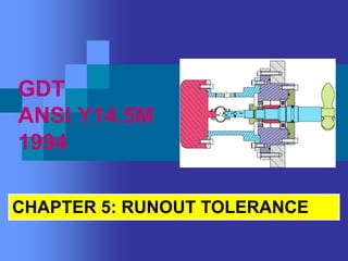
3. RUNOUT TOLERANCES
Definition
• Control relationship between the surfaces of
controlled features to datum axis of rotation.
• Control the form, location, and orientation
simultaneously
• The functional applications:
a. balancing
b. vibration
c. concentricity control due to the
rotating mass
Two types of runout tolerance:
1. circular runout
2. total runout
4. CIRCULAR RUNOUT
• Surface to datum axis control that applied to rotating
parts with respect to datum axis
• Control the form, orientation, and location of circular
element (individually) of a part feature relative to datum
axis
• Application:
1. Surface diameter (circumference surface)
- Control roundness, concentricity, wobbling
2. End surface
- Control flatness, wobbling, perpendicularity
11. TOTAL RUNOUT
• Control the entire surface elements to datum axis
that is applied to rotating part
• Control the form, orientation, and location of a part
feature simultaneously
• Application
i. Cylindrical Surface (circumference surface)
- control roundness, cylindricality, angularity,
concentricity, wobbling of entire surface diameter
ii. End surface
- control flatness, wobbling, perpendicularity
of entire end surface
15. Total runout applied to a diameter
In this application, thefollowing conditions
apply:
The diameter must meet its size
requirements.
The WCB is affected (24.6 + 0.2 = 24.8).
The runout control applies RFS.
The runout applies simultaneously to all
elements of the diameter.
The tolerance zone is two coaxial cylinders
0.2 apart.
The maximum possible axis offset is 0.1.
17. Total runout applied to a surface
The runout control applies RFS
The runout applies to all elements of the surface
simultaneously.
The shape of the tolerance zone is two parallel
planes perpendicular to the datum axis.
The runout symbol controls the angular
relationship (orientation) of the surface to the
datum axis.
The runout control also limits the flatness of the
surface.