Sheet Pile Wall Design and Construction: A Practical Guide for Civil Engineer...
Caldeira Roca R-20/20
1. 1
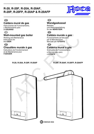
R-20, R-20F, R-20A, R-20AF,
R-20P, R-20FP, R-20AP & R-20AFP
R-20, R-20A, R-20P, R-20AP R-20F, R-20AF, R-20FP, R-20AFP
Wall-mounted gas boiler
Working and Maintenance
Instructions for
the USER
GB
Wandgaskessel
Betriebs-
und Wartungsanleitung
für den BENUTZER
D
Caldaia murale a gas
Funzionamento ed Istruzioni
per la Manutenzione.
Manuale per l’UTENTE
I
Caldeira mural a gás
IInstruções de Funcionamento
e Manutenção para
o UTENTE
P
Caldera mural de gas
Instrucciones de Funcionamiento,
y Mantenimiento para
el USUARIO
E
Chaudière murale à gaz
Instructions de Fonctionnement
et de Maintenance pour
l’USAGER
F
ATC
R
O
C
2. 2
Fig. 1
Fig. 3 Fig. 6
Fig. 7Fig. 4
Fig. 2 Fig. 5
Fig. 8
Fig. 9
Fig. 10
Fig. 11
Fig. 12
ATC
R
O
C
4. 4
Main characteristics
R-20, R-20F, R-20P and R-20FP: Boilers with
Heating service only.
Can supply Hot Water by accumulation if suitably
adapted. Consult your installer.
R-20A, R-20AF, R-20AP and R-20AFP: Boilers
with Heating service and Hot Water by
accumulation.
In the R-20F, R-20FP, R-20AF and R-20AFP,
combustion is separate from the air in the premises
(airtight chamber). The air required is taken directly
from out- side, and the gases produced are
evacuated by an extractor at the same time.
Heating service
Output: Adjustable from 6,000 kcal/h (7 kW) to
20,000 kcal/h (23,25 kW).
Maximum pressure in circuit: 3 bar.
Maximum temperature: 90°C.
Filling pressure: 1.5 bar.
Hot Water service (HWS) (*)
Output: Adjustable from 6,000 kcal/h (7 kW) to
20,000 kcal/h (23.25 kW).
Maximum pressure in circuit: 7 bar.
Maximum temperature 60°C
HWS priority in service
(1 kW = 860 kcal/h).
Regulation and control panel
See Figure 1.
Buttons
Wait / Stop
HWS Temperature selector. (*)
Heating circuit temperature selector.
R Reset after blockage.
Summer (HWS selection). (*)
Winter (Heating and DHW selection). (*)
To increase the temperature
To reduce the temperature
Screen symbols
Programming mode: HWS. (*)
Programming mode: Heating and HWS.(*)
Stoppage, anti-freeze protection.
HWS operating. (*)
Heating operating.
Bar Pressure in Heating circuit.
°C Temperature of Heating or HWS. (*)
Error codes.
Burners operating. Maximum output.
Burners operating. Medium output.
Burners operating. Minimum output.
Pilot lights
Green. Supply voltage.
Orange. Burners operating.
Red. Blockage.
Identification of the valves
See Figure 2.
1. Safety valve.
2. Heating out.
3. R-20A, R-20AF, R-20AP and R-20AFP: HWS
tank back.
4. Gas in.
5. Heating back.
6. Heating circuit purge cock.
Start-up
Check that the electrical connector is in the correct
position; it must be pressed firmly inwards. If you
need to leave the boiler without electrical supply,
it must be unplugged from the connector. See
Figure 3.
Open the front cover for access to the regulation
and control panel. The green pilot should be on.
If the green pilot does not light up, there is no
electrical supply to the boiler. Check to see if some
safety element at your mains entry is
disconnected.
Check the pressure in the heating circuit: it should
be at 1.5 bar. See Figure 4.
If error code 03 appears on the screen, it means
that there is not sufficient pressure in the Heating
circuit. The red pilot lights up. See Figure 5.
Check that the out and back cocks of the Heating
circuit are in the correct position; they should be
fully open. See Figure 6.
To increase pressure in the circuit, turn the flywheel
of the filler cock on the unit until it reaches 1.5 bar.
See Figure 7.
Once the correct pressure has been reached, the
flywheel must be closed. Error code 03 disappears
and the red pilot goes out.
Check that the circulator turns. Use a screwdriver
to remove the hub cap from the shaft and press
on the groove to make it turn. See Figure 8.
Ensure that the gas inlet cock (4) to the boilers is
open. See Figure 2.
The boiler will not star operating unless the ambient
thermostat (optional) is on demand for Heating.
Service selection
Winter: Heating and HWS (*)
Press this symbol for a moment to programme
the boiler to operate with Heating and HWS
service, giving preference to the latter. The
temperatures programmed in the boiler memory
are the following:
60°C for Hot Water.
90°C for Heating.
If the orange pilot lights up, the boiler is operating.
In this service, the data of Figure 9 will be
displayed. The temperature will rise until it reaches
the maximum temperature programmed
Summer: HWS (*)
Press this symbol for a moment to programme
the boiler to operate with the HWS service only.
In this service, the data in Figure 10 will be
displayed. The temperature will rise until it reaches
the maximum temperature programmed.
Stoppage
Press this symbol for a moment to cancel the
service programmed. See Figure 11.
In this position, a permanent system for protection
against freezing and blockage of the circulator is
activated (see section on ”Permanent protection”).
In order to resume the service, press or as
required.
Service temperature
The boiler allows you to adjust the initial factory
temperature settings. Proceed as follows:
Heating service
Press for a moment. See Figure 12.
Immediately, the temperature digits blink for 10
seconds.
During the interval, press if you wish to in-
crease the temperature, or you wish to reduce
it.
Once you have selected the new temperature, it
will be automatically recorded. The regulation
margin is from 30°C to 90°C.
(*) The Hot Water by accumulation service is available as
a standard feature only in R-20A, R-20AP, R-20AF and
R-20AFP boilers.
Hot Water service (*)
Press for a moment. See Figure 13.
Immediately, the temperature digits blink for 10
seconds.
During the interval, press if you wish to in-
crease the temperature, or you wish to reduce
it.
Once you have selected the new temperature, it
will be automatically recorded. The regulation
margin is from 40°
C to 60°
C.
Press for 10 seconds to reset the original
temperatures.
Maintenance
Must be performed once a year by specialized
personnel.
Error codes
If the red pilot lights up, it means that the boiler is
blocked.
R Press this button for 3-5 seconds and the boiler
will attempt to re-ignite. See Figure 16. If the boiler
blocks again, note the error code and inform your
installer or nearest after-sales service.
If the codes are 03, 06, 07, 12, 14, 15 or 17, check
the following points first:
03: Indicates a lack of pressure in the heating
circuit. Check the pressure and increase it by
opening the filler cock until it reaches 1.5 bar. The
boiler will start up automatically.
06 or 14: There may be pockets of air in the heating
circuit. Check that the cap of the purge trap at the
top of the boiler is open.
07: If this code appears, the boiler will start up
again automatically once it has recovered.
15: Means that the fume evacuation control de-
vice has been activated, due to a momentary
inversion of the fumes or defective evacuation.
Press R , and if this error is repeated, inform your
nearest after-sales service. When you press R ,
code 07 may appear. If so, the boiler will start up
again automatically once the recovery time has
elapsed.
12 or 17: Means that the burners will not ignite.
Check that the gas supply cocks are open. Re-
member that once they are open, you must press
R
Should any other code appear, inform your nearest
after-sales service.
Permanent protection
When the boiler is left at the position shown in
Figure 11, and independently of any conventional
protection systems, a permanent protection
system will operate on the circulator and burners,
giving the following services:
Antiblock
Activates the circulator for 15 seconds every 6
hours.
Anti-inertia
Following every Heating and/or DHW cycle, the
pump continues to run for a short period of time.
Antifreeze
If the temperature of the Heating circuit falls to
7°
C, the circulator is activated until it rises to 9°C.
Super antifreeze
If the temperature of the Heating circuit falls to
5°
C in extreme conditions, the programme
activates not only the circulator, but also the
ignition system, at the minimum output. The
burners will go out after 30 minutes or when the
temperature rises to 35°
C.
Recommendations
The peel-off film 2 which protects the control fascia
shoulb be removed.
It is recommended that professional services be
GB
ATC
R
O
C
5. 5
hired for the following operations:
Start-up of the boiler.
Adjustments.
Verification that the air inlets and ventilation of the
premises where the boiler is installed comply with
regulations.
If the boiler receives no electrical supply, the
permanent protection system will not be activated.
In this case, it will have to be emptied to avoid the
risk of freezing.
Fume evacuation safety
B11BS boilers (only R-20, R-20P, R-20A and
R-20AP) are equipped with a device for evacuation
control of the products of combustion. In the case
that the boiler observes any disturbance in the
evacuation of the said products, the gas supply
will be interrupted and the corresponding error
code will be displayed. See section on ”Error
codes”.
CE Marking
Roca wall-mounted gas boilers comply with
the European Directive 89/336/EEC on
Electromagnetic Compatibility, European
Directive 90/396/EEC on Gas Appliances,
European Directive 73/23/EEC on Low
Voltage, and European Directive 92/42/CEE
on Performance.
For version P boilers only
(Programmable)
Control panel
See Figure 1.
Additional buttons
A Cursor transfer to an operation mode.
B Time or function change adjustment.
C Programming adjustment.
D Daily programme copy.
Stop/start selector.
Additional screen symbols
Holiday operation mode.
PRO Weekly programming.
Manual operation mode.
Automatic operating mode.
Stop Heating service.
Star Heating service.
Weekday or holiday.
Actual time or time of function change.
Time adjustment.
Weekday adjustment.
... Changes of function
Programming the Heating
The boiler offers multiple programming options,
ensuring the right level of comfort at all times and
permitting considerable energy savings. In order
to programme the Heating service, proceed in the
following order:
Adjusting the day and time
Day of the week
Press A until PRO is highlighted. See Figure 18.
Press or until the right day is highlighted (1
is Monday, 2 is Tuesday, etc.).
Time of day
With the cursor at PRO , press B . See Figure 19.
Press or until the right time is displayed.
Holding one of the buttons down will enable you
to change the time faster.
Weekly programming
Up to 8 different changes of function can be
programmed each day. Each change must be
assigned a time and a stop order ( ) or start
order ( ). During the course of the day, the
boiler will execute the order programmed at the
time given.
A normal programme might be to start the day with
a start order and precede it with a stop order, as in
the standard programme. However, if necessary,
a series of stop and start orders may be assigned,
and the day may be started with a stop order.
The boiler will not change its operation in the
programming until it encounters an order which
cancels the previous one.
Programming a day
With the cursor at PRO , press C . See Figure 20.
The digit corresponding to the day appears on the
screen, with the first change ready to be
programmed.
a - Press or until the time required for the
change of function is displayed.
b - Press to assign an order ( or ). See
Figure 21.
Having selected the first change of the day, press
B to programme the second change (see Figure
22). Assign the time and order required, as
described above. (Steps a. and b.). Continue to
press the change function key ( B ), repeating
steps a. and b. to programme the remaining 6
changes of the day.
Note: The remaining time changes must be left at
00:00, with a stop order ( ). See Figure 23.
Programming the next day
There are two options:
- Repeat the programming of the previous day.
With the cursor at PRO , press C until you get
to the day you wish to copy. Press D .See
Figure 24. The digit corresponding to The next
day appears, along with its first change of
function: the full programme of the previous day
has been copied.
Press D again as many times as required to
repeat the programme of the previous day.
- Set a programme different from that of the
previous day. Press C . See Figure 25. The
following day appears, with the standard
programme. Proceed to programme it as
desired, following the steps described in the
previous section, ”Programming a day”.
Programme check
With the cursor at PRO , press C . See Figure 26.
The day and its first time change are displayed.
Press B to confirm that the programming is
correct, or else make the corrections required.
Press C to view the programming for the rest of
the week.
We recommend that you write your programme
on page 3.
Operating modes
There are 3 operating modes for the boiler in the
heating service:
Automatic mode
This is the normal operating mode. See Figure 27.
When in this position, the boiler operates according
to the programmes established.
Press A until is highlighted: the day, time and
order assigned are displayed. The programme will
be carried out automatically.
Important: If, due to some change in your
timetable, you wish to invert the current
programmed order, press . See Figure 28.
The boiler will resume the established
programme at the next change of function. You
may use this option as often as you need to,
without affecting the weekly programme.
Manual mode
Press A until is highlighted. See Figure 29.
The day, time and continual operation order are
displayed. In this mode, the boiler will operate
continually without taking the programming into
account. It will only stop if triggered by an ambient
thermostat or, if there are none, when the selected
Heating temperature is reached.
Continual stop or start orders may be entered by
pressing .
Holiday mode
Press A until is highlighted: The time and
days of holidays are displayed. See Figure 30.
Press or to indicate the days of absence.
The boiler will remain inactive for that period, and
will start up again automatically on the day of your
return.
Remarks
The stop order ( ) does not interrupt the DHW
service. See Figure 31.
If no electricity is reaching the boiler, the screen
will display the symbol of the service that was being
offered and the time. See Figure 32. In this case,
the programmes will remain in memory for
approximately 30 daies.
ATC
R
O
C