
Recommended
Recommended
More Related Content
What's hot
What's hot (20)
Similar to Caterpillar cat dp150 forklift lift trucks service repair manual sn:6 dp00013 and up
Similar to Caterpillar cat dp150 forklift lift trucks service repair manual sn:6 dp00013 and up (20)
More from jksjekmd
More from jksjekmd (20)
Recently uploaded
Recently uploaded (20)
Caterpillar cat dp150 forklift lift trucks service repair manual sn:6 dp00013 and up
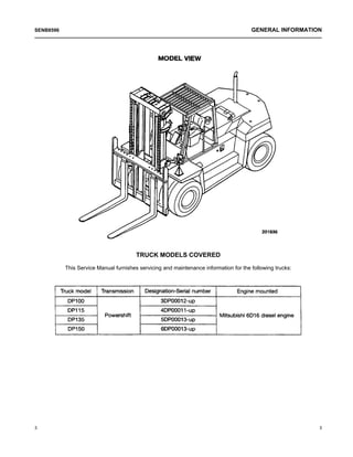
- 1. TRUCK MODELS COVERED This Service Manual furnishes servicing and maintenance information for the following trucks: 3 3 SENB8596 GENERAL INFORMATION
- 2. NAMEPLATE AND SERIAL NUMBER LOCATIONS SENB8596 GENERAL INFORMATION 4 4
- 3. TECHNICAL DATA 5 5 SENB8596 GENERAL INFORMATION
- 4. DIMENSIONS (APPROXIMATE) SENB8596 GENERAL INFORMATION 6 6
- 5. 7 7 SENB8596 GENERAL INFORMATION
- 6. SPECIFICATIONS 9 9 SENB8596 COOLING SYSTEM
- 7. SENB8596 COOLING SYSTEM 10 10 DESCRIPTION The radiator with a tube-and-fin type core comes standard. The fins are corrugated. The cooling fan is of pusher type and has eight blades to provide high cooling efficiency. The lower tank has a built-in transmission oil cooler which, in operation, is constantly removing heat from the transmission oil returning from the torque converter.
- 8. 11 11 SENB8596 COOLING SYSTEM REMOVAL AND INSTALLATION Start by: a) Remove the gas-filled cylinder and engine hood. b) Remove the radiator cover. c) Loosen the radiator drain cock to drain coolant from the radiator.
- 9. Suggestions for removal (1) Fasten a hoist to the radiator and sling the radiator. (2) Remove the radiator mounts (at 4 places) and lift off the radiator. Inspection (1) Blow dirt and bugs, if any, from the radiator fins with compressed air. Be careful not to bend the fins because this will decrease cooling efficiency. (2) Replace the radiator if the fins are damaged beyond repair. (3) Check the rubber cushions of the radiator mounts for condition. Replace them if damaged or deteriorated. (4) Check the radiator hoses, upper and lower, for condition. Replace them if defective. Installation To install, follow the reverse of removal sequence. (1) Slide the hoses on to the tubes of the radiator and tighten all the clamps. Make sure the hoses are properly clamped at flared portions of the tube. (2) Fill the cooling system with coolant to the correct level. Start the engine and, with the engine running at low idle, listen for any abnormal noise. Check to be sure the coolant level in the reserve tank is correct. SENB8596 COOLING SYSTEM 12 12
- 10. TROUBLESHOOTING 13 13 SENB8596 COOLING SYSTEM
- 11. SPECIFICATIONS 15 15 SENB8596 ELECTRICAL SYSTEM
- 12. LOCATION OF COMPONENTS For the components to which harnesses A, B and C are connected, see the pages which follows. SENB8596 ELECTRICAL SYSTEM 16 16
- 13. Harness A 17 17 SENB8596 ELECTRICAL SYSTEM
- 14. Circuit numbers and color codes of harness A SENB8596 ELECTRICAL SYSTEM 18 18
- 15. Harness B (on the left side of engine room) 19 19 SENB8596 ELECTRICAL SYSTEM
- 16. Harness C (on the right side of engine room) SENB8596 COOLING SYSTEM 20 20
- 17. DESCRIPTION Console Box 1 Engine coolant temperature gauge 2 Torque converter oil temperature gauge 3 Fuel gauge 4 Hour meter 5 Central vehicle monitoring system 6 Starter switch 7 Lighting switch 8 OK monitor check switch 9 Fuse box 10 Speed selector switch Central vehicle monitoring system 21 21 SENB8596 ELECTRICAL SYSTEM
- 18. Components in console box SENB8596 ELECTRICAL SYSTEM 22 22 Spare power source (terminal) The spare terminal is located on the lead from the fuse box in the control box. (Another spare terminal is located on the main harness side of the chassis.) Cord color: LG (yellow/green) The step required to gain access to the spare terminal is to remove the rear panel of the control box. The terminal is taped to the harness protector.
- 19. Side Instrument Panel 23 23 SENB8596 ELECTRICAL SYSTEM
- 20. Fuses SENB8596 ELECTRICAL SYSTEM 24 24 Optional fuses
- 21. Major Components Electronic control unit (ECU) 25 25 SENB8596 ELECTRICAL SYSTEM The electronic control unit (ECU) has a built-in 1-chip microcomputer. This computer processes signals from the travel speed sensor for actuating the speed selector system. The ECU has “self-diagnostic” failure indicator lights which come on when any problem occurs in the electrical system, thereby allowing the operator to locate the problem. It has the following fail-safe systems so that failure of power, control circuit, or other components will not endanger the operator. Fail-safe system
- 22. Starter switch (anti-restart type) This switch has a built-in mechanical lockout. This lockout restrains the key from turning to START position from ON position (as when the engine is SENB8596 ELECTRICAL SYSTEM 26 26 running) help to prevent damage to the starter pinionor flywheel ring gear. The ON position of the switch is for energizing the air heater. Light Switch
- 23. LIGHT BULB SPECIFICATIONS 27 27 SENB8596 ELECTRICAL SYSTEM
- 24. Combination Meter Disassembly 29 29 SENB8596 ELECTRICAL SYSTEM Assembly Follow the reverse of disassembly sequence.
- 25. Indicator bulb replacement 1. Rear panel removal (on machine) (1) Remove the screws (four) that hold the rear panel, and separate the rear panel from the meter panel and front panel. (2) Remove the bulbs from the printed circuit board by turning them counterclockwise. 2. Location of bulbs (on printed circuit board) 1 Brake fluid level indicator 2 Fuel filter indicator (option) 3 Air heater indicator 4 Alternator indicator 5 Engine oil pressure indicator 6 Turn signal indicator 7 Air cleaner indicator (option) 8 Fuel level indicator (option) 9 Engine coolant level indicator (option) 10 Working light indicator (option) 11 High-beam indicator (option) 12 Instrument panel light SENB8596 ELECTRICAL SYSTEM 30 30
- 26. Side Instrument Panel Disassembly 31 31 SENB8596 ELECTRICAL SYSTEM
- 27. Assembly Follow the reverse of disassembly sequence. SENB8596 ELECTRICAL SYSTEM 32 32
- 28. BATTERIES 1. Electrolyte specific gravity (S.G.) reading and battery condition 33 33 SENB8596 ELECTRICAL SYSTEM To check the battery for charging, take hydrometer readings on its electrolyte: the battery may be deemed to be fully charged if the readings are between 1.260 and 1.280 at normal temperature. The tendency of the charging system can be told from the way the electrolyte level goes down to expose cell plates. If refilling (with distilled water) is necessary every month or so, the system is tending to over-charge the battery. If refilling is not required for over 3 months, it is likely that the system is inadequately charging. 2. Precautions for battery charging (1) In slow-charging a dead battery, the charging current should be about 1/10 the capacity of the battery to be charged. (2) In quick-charging the battery, the battery capacity in ampere should not be exceeded. (3) During charging, adjust the charging current to prevent the battery electrolyte temperature from rising beyond 45°C (113°F). (4) When connecting the cables to the battery, begin with the cable for the positive (+) terminal. When disconnecting them from the battery, begin with the cable for the negative (–) terminal.
- 29. Installation of automatic engine stop solenoid 1. Install the solenoid switch and levers in position on the bracket. 2. Push plunger (1) in all the way. Move stop lever (2) (engine side) all the way to STOP position. Under this condition, adjust the length of solenoid rod (3) and connect it to the lever. 3. After installing the switch, move the engine stop lever to RUN position by hand to make sure the plunger end is not projecting from the solenoid switch. SENB8596 ELECTRICAL SYSTEM 34 34
- 30. TROUBLESHOOTING Starter System 35 35 SENB8596 ELECTRICAL SYSTEM
- 31. Lighting System SENB8596 ELECTRICAL SYSTEM 36 36
- 32. 37 37 SENB8596 ELECTRICAL SYSTEM
- 33. Thank you very much for your reading. Please Click Here Then Get More Information.