Mobile Wire Shelving Installation Instructions
•
1 like•1,147 views

Mobile Wire Shelving Installation Instructions, Southwest Solutions Group, www.southwestsolutions.com, 1-800-803-1083

Recommended
More Related Content
What's hot
Similar to Mobile Wire Shelving Installation Instructions
Similar to Mobile Wire Shelving Installation Instructions (17)
More from Installation Manuals - Southwest Solutions Group
More from Installation Manuals - Southwest Solutions Group (7)
Recently uploaded
Recently uploaded (20)
Mobile Wire Shelving Installation Instructions
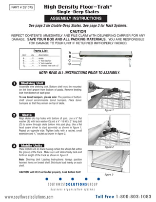
- 1. EG10030 Rev 10/09 ASSEMBLY INSTRUCTIONS High Density Floor-Trak® Single-Deep Skates See page 2 for Double-Deep Skates. See page 3 for Track Systems. PART # 351375 Assemble wire shelving unit. Bottom shelf must be mounted on the third groove from bottom of posts. Remove leveling bolt from bottom of each post. To use donut bumpers, please note: The position of bottom shelf should accommodate donut bumpers. Place donut bumpers so that they remain on top of skate. 1 Shelving Unit Align skates (A) top holes with bottom of post. Use a 3 ⁄8˝ flat washer (B) with lock washer(C) and a 3 ⁄8˝ -16 NC x 2˝ long bolt (D) to screw through skate bottom into post plug. Use a flat head screw driver to start assembly as shown in figure 1. Repeat on opposite side. Tighten bolts with a ratchet, small extension and 9 ⁄16˝ socket as shown in figure 2. 2 Skate Place mobile unit on track making certain the wheels fall within the groove of the track. Make sure unit slides freely back and forth on length of the track as shown in figure 3. Note: Shelving Unit Loading Instructions: Always position heaviest items on lowest shelf. Distribute load evenly on each shelf. 3 Mobile Units CAUTION INSPECT CONTENTS IMMEDIATELY AND FILE CLAIM WITH DELIVERING CARRIER FOR ANY DAMAGE. SAVE YOUR BOX AND ALL PACKING MATERIALS. YOU ARE RESPONSIBLE FOR DAMAGE TO YOUR UNIT IF RETURNED IMPROPERLY PACKED. Parts List A. . . . . . . 2. . . .. skate B. . . . . . . 4. . . .. 3 ⁄8˝ flat washer C. . . . . . . 4. . . .. 3 ⁄8˝ lock washer D2 . . . . . . 4. . . .. 3 ⁄8˝ slotted hex bolt x 2˝ item qty description A B C D figure 1 figure 2 figure 3 CAUTION: will tilt if not loaded properly. Load bottom first! Eagle Foodservice Equipment, Eagle MHC, SpecFAB, and Retail Display are divisions of Eagle Group. ©2009 by the Eagle Group • 100 Industrial Boulevard, Clayton, Delaware 19938-8903 U.S.A. • www.eaglegrp.com • Phone: 302/653-3000 • (Foodservice/SpecFAB) 800/441-8440 • (MHC/Retail) 800/637-5100 • Fax: 302/653-2065 NOTE: READ ALL INSTRUCTIONS PRIOR TO ASSEMBLY. www.southwestsolutions.com
- 2. Assemble the wire shelving unit. Bottom shelf must be mounted on the third groove from bottom of posts. Remove leveling bolt from the bottom of each post. Additional Notes: • Shelving unit requires ‘standard posts’ at one end and ‘end posts’ at the other. ‘End posts’ have inserts at both top & bottom, and go in the middle of a double-deep assembly. • To use donut bumpers, please note: The position of the bottom shelf should accommodate donut bumpers. Place donut bumpers so that they remain on top of the skate. 1 Shelving Unit ASSEMBLY INSTRUCTIONS High Density Floor-Trak® Double-Deep Skates Place spacer(M) on top of the skate. Align skates(A) top holes with the hole in the spacer and the bottom of post. Use a 3 ⁄8˝ flat washer(B) with lock washer(C) and a 3 ⁄8˝ - 16x2˝ bolt(D2) to screw through skate bottom into post plug. Use a flat head screw driver to start assembly as shown in figure 1. Repeat on opposite side. Tighten bolts with a ratchet, small extension and 9 ⁄16˝ socket as shown in figure 2. 2 Attaching Skates to Standard Posts Place center tie bar(L) on top of the skate. Align skates(A) top holes with the middle hole in the center tie bar. See “for End Posts” sequence above. Use two 3 ⁄8˝ flat washers(B) with lock washers(C) and a 3 ⁄8˝-16x11 ⁄4˝ bolt(D1.25) and acorn nut(E) to attach center tie bar(L) as shown in figure 3. Use a flat head screw driver to start assembly. Repeat on opposite side. Attach wire shelving units to sides of center tie bar on skate (see “Double-Deep Unit” on back page). Use a 3 ⁄8˝ flat washer(B) with lock washer(C) and 3 ⁄8-16x2 bolt(D2) to screw through center tie bar and into the bottom of the post as show in figure 3. Tighten bolts with a ratchet, small extension and 9 ⁄16˝ socket as shown in figure 2. Place center tie bar on top of posts and secure using a 3 ⁄8˝ flat washer(B) with lock washer(C) and 3 ⁄8-16x2 bolt(D2) as shown in figure 3a. 3 Attaching Skates to End Posts Place mobile unit on track making certain the wheels fall within the groove of the track. Make sure unit slides freely back and forth on the length of the track as shown in figure 4 before securing track to floor. Note: Shelving Unit Loading Instructions; Always position the heaviest items on the lowest shelf. Distribute load evenly on each shelf. 4 Mobile Units Parts List A. . . . . . . 3. . . .. skate B. . . . . . . 16. . . .3 ⁄8˝ flat washer C. . . . . . . 14. . . .3 ⁄8˝ lock washer D1.25 . . . . 2 . . . . 3 ⁄8˝ slotted hex bolt x 11 ⁄4˝ D2 . . . . . . 12. . . .3 ⁄8˝ slotted hex bolt x 2˝ E. . . . . . . 2 . . . . 3 ⁄8˝ acorn nut L . . . . . . . 4 . . . . center tie bar M . . . . . . 4 . . . . spacer item qty description A for Standard Posts: for End Posts: M E C B L D1.25 B B C D2 figure 1 figure 2 figure 3 figure 3a figure 4 L E L READ ALL INSTRUCTIONS PRIOR TO ASSEMBLY. 2 www.southwestsolutions.com
- 3. IMPORTANT NOTE: Make sure floor is level. If floor is not level, shims are required. Shim Kit #912991 available upon request. IMPORTANT NOTE: Parts List F. . . . . . . 2 per length . . . . . track G . . . . . . 2 per track. . . .. . . . extension pins H. . . . . . . 2 per track. . . .. . . . end stop I . . . . . . . 2 per track . . . . . . . anchor bolt J . . . . . . . 2 per track joint. . . . track rivet K. . . . . . . as required. . . . . . . s/s insert . . . . . . . . 1. . . . . . . . . . . . . . . 1 ⁄4˝ drill bit item qty description Lay tracks (F) on floor parallel to each other. Install stainless steel inserts (K) to fill track as shown in figure 1. For additional track length, place pins (G) as shown in figure 2, to the underside of the track to connect tracks together. Note: Should installation require resizing of the tracks, steel inserts must run the entire length of the assembled track. 1 Tracks Place mobile unit on track making sure wheels are in slots. Align each end and make sure units slide back and forth freely. Note: Using a lightly loaded mobile unit will maintain track alignment while securing track. 2 Mobile Units Slide one end stop (H) into track end as shown in figure 3. Use 1 ⁄4˝ drill bit provided to drill straight down into and through end stop and track (approx. 2˝) into floor as shown in figure 3a. Now, hammer securely and seat anchor bolt (I) until flush as shown in figure 3b. Repeat on same end of opposite track that is running parallel. Note: Keep mobile unit 12˝ to 18˝ from end of track being secured to insure that distance between each track is correct. Note: Use mobile unit to keep track parallel while securing from one end stop to other. 3 End Stops At each track joint, slide mobile unit across track joint and stop when track joint is centered and unit moves freely back and forth. Using the drill, position into guide line and drill diagonal through track (approximately 2˝) from joint seam as shown in figure 4. Place track rivet (J) into hole and secure with a hammer. Repeat procedure on opposite side. 4 Joining Track Lengths Apply silicone sealant around track edge and floor. 5 Seal Track Perimeter to Floor figure 2 figure 3b figure 1 figure 4 figure 3 figure 3a ASSEMBLY INSTRUCTIONS High Density Floor-Trak® Track Systems G H I J K track joint hole placement hole placement READ ALL INSTRUCTIONS PRIOR TO ASSEMBLY. 3 www.southwestsolutions.com
- 4. Single-Deep Unit Double-Deep Unit skate skate shelving units end stop end stop center tie bar and skate track track standard posts standard postsend posts end posts spacer and skate spacer and skate Eagle Foodservice Equipment, Eagle MHC, SpecFAB, and Retail Display are divisions of Eagle Group. ©2009 by the Eagle Group • 100 Industrial Boulevard, Clayton, Delaware 19938-8903 U.S.A. • www.eaglegrp.com • Phone: 302/653-3000 • (Foodservice/SpecFAB) 800/441-8440 • (MHC/Retail) 800/637-5100 • Fax: 302/653-2065 www.southwestsolutions.com