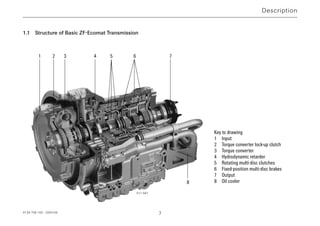
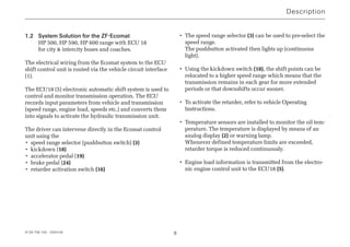
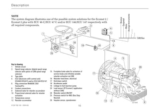
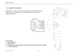
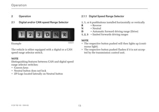
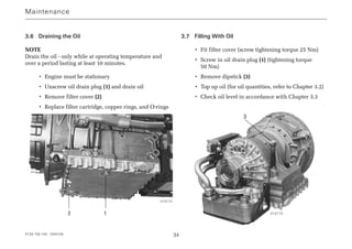
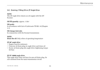
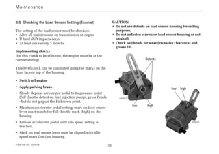
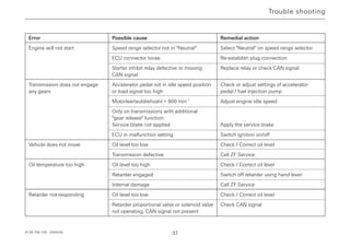
Operating
Instructions
4139 758 103
ZF-Ecomat
HP 500 HP 590 HP 600
ZF-Ecomat 2 / ZF-Ecomat 2 plus
HP 502 HP 592 HP 602
HP 502C HP 592C HP 602C
for city and intercity buses and
coaches
Subject to alterations in design
Copyright by ZF
This documentation is protected by copyright. Any repro-
duction or dissemination in whatever form which does not
comply fully with the intended purpose of this documen-
tation is prohibited without the consent of ZF Friedrichs-
hafen AG.
Printed in Germany
ZF Friedrichshafen AG, MC-C / 2004-09
Edition: 2006-02
Preface
Before the vehicle first enters service, please note the
following points:
• Read the Operating Instructions carefully and follow the
safety instructions.
• To ensure that the transmission achieves the required
level of operational safety and reliability, always pay
careful attention to the maintenance instructions.
The ZF After-Sales Service specialists are available to
assist you in carrying out maintenance work at the trans-
mission or to help if any other problems arise. Their
addresses are listed in the "ZF Company Directory" (order
number 0000 762 703) or on the Internet under
www.zf.com/ servicenetz.
NOTE
All details in these Operating Instructions refer to the
basic version of the ZF-Ecomat transmission. Due to the
large number of installation options, no precise informati-
on can be provided for any specific vehicle. If there are
any differences in operation between the instructions in
this brochure and the Operating Instructions specific to an
individual vehicle manufacturer, the vehicle-specific
instructions are the ones to follow.
Motoring pleasure with the ZF-Ecomat is brought to you
by
ZF Friedrichshafen AG
Commercial Vehicle and Special Driveline Technology
D-88038 Friedrichshafen
Tel.: +49 (0)7541 77-0
Fax: +49 (0)7541 77-90 80 00
Internet: www.zf.com
4139 758 103 - 2004-09 3
The following safety instructions appear in this manual:
NOTE
Refers to special processes, methods, information, etc.
CAUTION
This is used when incorrect, unprofessional working
practices could damage the product.
DANGER !
This is used when lack of care could lead to
personal injury or material damage.
THREATS TO THE ENVIRONMENT !
Lubricants and cleaning agents must not be allowed to
enter the soil, ground water, or sewage system.
• Ask your local environment agency for safety
information on the relevant products and adhere
to their requirements.
• Collect used oil in a suitably large container.
• Dispose of used oil, dirty filters, lubricants, and
cleaning agents in accordance with environmental
protection guidelines.
• When working with lubricants and cleaning agents
always refer to the manufacturer's instructions.
NOTE on cleaning the vehicle / transmission
CAUTION
When cleaning, always ensure that the steam cleaner or
high-pressure cleaner does not make direct contact with
the screw cap of the dipstick. Any water ingress through
the breather can damage the transmission!
!
!
Safety Instructions
4139 758 103 - 2004-09 4
1 Description . . . . . . . . . . . . . . . . . . . . . . . . . . . 6
1.1 Structure of Basic ZF-Ecomat Transmission . . . . . . . 7
1.2 System Solution for ZF-Ecomat . . . . . . . . . . . . . . . . 9
1.3 System Solution for ZF-Ecomat 2/
ZF-Ecomat 2 plus . . . . . . . . . . . . . . . . . . . . . . . . . . 11
1.4 Auxiliary Transmission . . . . . . . . . . . . . . . . . . . . . . . 12
2 Operation . . . . . . . . . . . . . . . . . . . . . . . . . . . 13
2.1 Speed Range Selector . . . . . . . . . . . . . . . . . . . . . . 13
2.1.1 Digital Speed Range Selector . . . . . . . . . . . . . . . . . 13
2.1.2 CAN Speed Range Selector . . . . . . . . . . . . . . . . . . 14
2.2 Starting Engine . . . . . . . . . . . . . . . . . . . . . . . . . . . . 15
2.3 Engaging Gear . . . . . . . . . . . . . . . . . . . . . . . . . . . . 15
2.4 Setting Off . . . . . . . . . . . . . . . . . . . . . . . . . . . . . . . 16
2.5 Speed Ranges . . . . . . . . . . . . . . . . . . . . . . . . . . . . 17
2.5.1 Driving Downhill . . . . . . . . . . . . . . . . . . . . . . . . . . . 17
2.5.2 Change in Direction of Travel . . . . . . . . . . . . . . . . . . 17
2.5.4 Retarder Operation . . . . . . . . . . . . . . . . . . . . . . . . . 19
2.6 Stopping, Parking . . . . . . . . . . . . . . . . . . . . . . . . . . 21
2.7 Towing . . . . . . . . . . . . . . . . . . . . . . . . . . . . . . . . . . 22
2.7.1 Towing a Vehicle with Operational Transm. . . . . . . . 22
2.7.2 Towing a Vehicle with Suspected Transmission
Damage . . . . . . . . . . . . . . . . . . . . . . . . . . . . . . . . . 22
2.8 Temperature Monitoring . . . . . . . . . . . . . . . . . . . . . 23
2.9 Limit Values for Oil Temperature . . . . . . . . . . . . . . . 23
2.9.1 Transmission Oil Temperature Upstream of Oil Cooler 23
2.9.2 Oil Temperature in Transmission Sump . . . . . . . . . . 23
2.9.3 Action When Permitted Oil Temperature Limit is
exceeded . . . . . . . . . . . . . . . . . . . . . . . . . . . . . . . . 24
2.10 Status Monitoring / Warning Lamps . . . . . . . . . . . . 24
2.11 Transmission Response to a Malfunction . . . . . . . . . 25
2.11.1 Limp-Home Mode . . . . . . . . . . . . . . . . . . . . . . . . . . 25
2.12 Auxiliary Control Unit . . . . . . . . . . . . . . . . . . . . . . . 26
2.12.1 Operating Instructions for the Auxiliary Control Unit 26
3 Maintenance . . . . . . . . . . . . . . . . . . . . . . . . . 28
3.1 Oil Grade . . . . . . . . . . . . . . . . . . . . . . . . . . . . . . . . 28
3.2 Oil Quantities in the ZF-Ecomat . . . . . . . . . . . . . . . 29
3.3 Oil Level Check . . . . . . . . . . . . . . . . . . . . . . . . . . . . 29
3.3.1 Checking at Operating Temperature . . . . . . . . . . . . 30
3.3.2 Reference Value Calculation . . . . . . . . . . . . . . . . . . 30
3.3.3 Checking With Separate Heat Exchanger
Mounted Above Centerline of Transmission . . . . . . . 32
3.4 Option for Heating Up the Transmission Oil . . . . . . . 32
3.5 Oil Change Intervals . . . . . . . . . . . . . . . . . . . . . . . . 33
3.6 Draining the Oil . . . . . . . . . . . . . . . . . . . . . . . . . . . . 34
3.7 Filling With Oil . . . . . . . . . . . . . . . . . . . . . . . . . . . . 34
3.8 Draining / Filling Oil on ZF Angle Drive . . . . . . . . . . 35
3.9 Checking the Load Sensor Setting (Ecomat) . . . . . . 36
Trouble shooting . . . . . . . . . . . . . . . . . . . . . . . . . . .37
Contents
4139 758 103 - 2004-09 5
4139 758 103 - 2004-09 6
1 Description
The Ecomat range of transmissions comprises a hydrody-
namic torque converter (Föttinger t/c) with lock-up clutch,
a hydrodynamic retarder, and a downstream, multi-ratio
planetary transmission.
The torque converter is a starting unit which operates
without mechanical wear and which adapts its setting
across an infinitely variable range to suit prevailing condi-
tions (delivering the required level of input torque).
The gears in the planetary transmission are engaged
automatically without any interruption in traction. The
signals for gear changes are supplied by an ECU (electro-
nic shift control unit). Depending on various parameters
obtained from vehicle and transmission, this ECU engages
the appropriate multi-disc clutches and brakes via the
electro-hydraulic transmission control unit.
A lock-up clutch installed in the torque converter establis-
hes a direct mechanical connection between engine and
planetary transmission after the starting phase. This lock-
up process eliminates the power losses traditionally asso-
ciated with torque converter transmission.
The hydrodynamic retarder is installed between the tor-
que converter and the planetary transmission. This means
that the level of retarder braking force on the output shaft
is gear-dependent. As a consequence, full braking action is
available, even at the lower end of the speed range. The
braking torque can be controlled across an infinitely
variable range or can be sub-divided into several steps.
Braking action while driving downhill or in city traffic can
be delivered by the retarder without mechanical wear,
thereby extending the life of the service brakes.
ZF offers a range of powerful PTOs for the entire range of
Ecomat applications. These PTOs are engine-dependent
and, depending on their version are either permanently
driven or disengagable.
Description
Description
1 2 3 4 5 6 7
8
1.1 Structure of Basic ZF-Ecomat Transmission
Key to drawing
1 Input
2 Torque converter lock-up clutch
3 Torque converter
4 Hydrodynamic retarder
5 Rotating multi-disc clutches
6 Fixed-position multi-disc brakes
7 Output
8 Oil cooler
011 561
4139 758 103 - 2004-09 7
4139 758 103 - 2004-09 8
Description
000810
4 9 8
4
21
2019
16
1817
15
023807
1 2 3 4
4
84 7 91013
14
16
17
187 19 20 21
22 23
24
7
12 11
5
6
15
BN 2
BN 1
NOTE
This system diagram illustrates one of the possible system solutions for the ZF-Ecomat with the ECU 18 electronic
shift control unit and all related components.
Key tto ddrawing
1 Vehicle circuit interface
2 Temperature display unit
3 Speed range selector (digital speed
range selector)
4 Type plate
5 ECU 18 electronic shift control unit
6 Plug connection for
MOBiDIG 2000 / ZF-TestmanPro
7 From air supply for auxiliary
consumers
8 Coolant connections
9 Solenoid valve for retarder accumulator
10 Retarder accumulator
11 Solenoid valve for retarder activation
12 Temperature sensor
13 Pressure relief valve (1.2 bar)
14 Solenoid valve for retarder torque
reduction
15 Pressure switch (retarder input signal
for ECU 18)
16 Footplate brake valve with modulator valve for
activating the service brake
17 Retarder hand lever
18 Kickdown switch
19 Accelerator pedal
20 Linkage for fuel injection pump
21 Load sensor for recording engine load status
22 Compressed air line for retarder activation (optional
15 and/or 16). Pressure line for modulated pressure
(0 to 3 bar)
23 Changeover valve
24 Brake pedal for service brake
activation 023807
4139 758 103 - 2004-09 9
1.2 System Solution for the ZF-Ecomat
HP 500, HP 590, HP 600 range with ECU 18
for city & intercity buses and coaches.
The electrical wiring from the Ecomat system to the ECU
shift control unit is routed via the vehicle circuit interface
(1).
The ECU18 (5) electronic automatic shift system is used to
control and monitor transmission operation. The ECU
records input parameters from vehicle and transmission
(speed range, engine load, speeds etc.) and converts them
into signals to activate the hydraulic transmission unit.
The driver can intervene directly in the Ecomat control
unit using the
• speed range selector (pushbutton switch) (3)
• kickdown (18)
• accelerator pedal (19)
• brake pedal (24)
• retarder activation switch (16)
• The speed range selector (3) can be used to pre-select the
speed range.
The pushbutton activated then lights up (continuous
light).
• Using the kickdown switch (18), the shift points can be
relocated to a higher speed range which means that the
transmission remains in each gear for more extended
periods or that downshifts occur sooner.
• To activate the retarder, refer to vehicle Operating
Instructions.
• Temperature sensors are installed to monitor the oil tem-
perature. The temperature is displayed by means of an
analog display (2) or warning lamp.
Whenever defined temperature limits are exceeded,
retarder torque is reduced continuously.
• Engine load information is transmitted from the electro-
nic engine control unit to the ECU18 (5).
Description
4139 758 103 - 2004-09 10
Description
1 2 3 D N R
17
62019
5
3
15
18
24
25
4
16
1
4
4
10
9
26
12
8
CAN-Bus
Bremse
Gaspedal
Motor
Anzeige-Instrumente
.........
.......
11
021649
NOTE
The system diagram illustrates one of the possible system solutions for the Ecomat 2 /
Ecomat 2 plus with ECU 46 C/ECU 47 C and/or ECU 146/ECU 147 respectively with
all required components.
Key tto ddrawing
1 Vehicle circuit
3 Speed range selector (digital speed range
selector with option of CAN speed range
selector)
4 Type plate
5 ECU (electronic shift control unit)
ECU46C/ECU47C and/or ECU146/ECU147
6 Plug connection MoBiDIG 200/
TestmanPro
8 Coolant connections
9 Solenoid valve for retarder accumulator
10 Proportional solenoid valve for retarder
activation
11 Temperature sensor
12 Retarder accumulator
15 Footplate brake valve for activation of
service brake and infinitely variable
retarder activation via CAN
16 Retarder hand lever, electrical
17 Kick-down switch
18 Accelerator pedal
19 Linkage to fuel injection pump
20 Load sensor (ZF-Ecomat-2 application
without CAN)
24 Retarder switch ON/OFF
25 Pressure switch for NBS (Bus Stop
Neutral)
26 Impulse sensor, speedometer
4139 758 103 - 2004-09 11
1.3 System Solution for ZF-Ecomat 2/ZF-Ecomat 2
plus
HP 502, HP 592, HP 602 range and/or ECU 502 C and
HP 592 C, HP 602 C with ECU46C / ECU47C and
ECU 146 / ECU 147 respectively, for city & intercity
buses and coaches (C=CAN-capable)
The electrical wiring from the Ecomat system is routed to
the ECU and to the CAN bus in the vehicle via the vehicle
circuit interface (1).
The (electronic automatic shift system) ECU helps to con-
trol and monitor operation of the transmission. The ECU
records input parameters from vehicle and transmission
(speed range, engine load, speeds etc.) and processes these
into signals to activate the hydraulic transmission control
unit.
The driver can intervene directly in the Ecomat control
unit using the
• speed range selector (pushbutton switch) (3)
• kickdown (pushbutton switch) (18)
• accelerator pedal (19)
• brake pedal (24)
• retarder activation switch (16)
• The speed range selector (3) can be used to pre-select the
speed range. The pushbutton activated then lights up
(continuous light).
• Using the kickdown switch (17) the shift points can be
relocated to a higher speed range, i.e. the transmission
then spends longer in each ratio before upshifts and that
downshifts occur sooner.
• Activation of the retarder: Refer to vehicle Operating
Instructions.
• Temperature sensors are installed to monitor the oil tem-
perature. This information is transmitted via CAN bus,
digital output on the ECU or via direct wiring and is dis-
played by means of a display panel, analog display or
warning lamp. Whenever defined temperature limits are
exceeded, retarder torque is reduced continuously.
• Engine load information is transmitted from the electro-
nic engine control unit to the ECU by means of CAN or
load sensor (20) or PWM signal.
In conjunction with a proportional solenoid in the elect-
ro-hydraulic control unit, pressures for activating the
clutch elements are modulated in accordance with engi-
ne load.
• Special feature of the Ecomat 2 plus:
This range of transmissions has been designed to con-
tend with higher temperatures by means of a choice of
modified sub-assemblies built with adapted materials,
refer to Chapter 2.9.
Description
!
"
4139 758 103 - 2004-09 12
Description
019994
Key to drawing:
1 Basic transmission
2 Coaxial output
3 80° angle drive without LHD axial offset or 80° angle drive with RHD axial offset RHD
4 ST 10000 angle drive
1.4 Auxiliary Transmission
Depending on vehicle version and application, the ZF-Ecomat trans-
mission can be equipped with an 80° angle drive or with an ST
10000 angle drive.
4139 758 103 - 2004-09 13
2 Operation
2.1 Digital and/or CAN speed Range Selector
Example
The vehicle is either equipped with a digital or a CAN
speed range selector switch.
NOTE
Distinguishing features between CAN and digital speed
range selector switches:
• Convex keys
• Neutral button does not lock
• ZF-Logo located laterally on Neutral button
2.1.1 Digital Speed Range Selector
3, 5, or 6 pushbuttons installed horizontally or vertically
R = Reverse
N = Neutral
D = Automatic forward driving range (Drive)
1, 2, 3 = limited forwards driving ranges
NOTE
• The respective button pushed will then lights up (conti-
nuous light).
• The respective button pushed flashes if it is not accep-
ted by the transmission control unit.
Operation
005624
2.1.2 CAN Speed Range Selector
2.1.2.1 Lighting of the CAN Speed Range Selector
Button lighting colors:
• Neutral button: Amber
• 1,2,3, D and R: Yellow
All buttons light up for approx. 1.2 s:
• Lighting test at system startup
All buttons flash:
• Serious internal fault in pushbutton
• Malfunction in CAN communication. Once this defect
has been remedied, the lamp stops flashing.
All lamps light up dimly:
• Search lighting: To make it easier to find the buttons in
the dark.
Individual buttons light up brightly:
• Function lighting: Identifies the active, pressed
pushbutton.
Exceptions:
• If the transmission control unit is not providing the
information required for lighting purposes, the lamps
only light up in search mode. Nevertheless, the vehicle
can still be driven in this status.
• The lighting is also deactivated if the pushbutton positi-
on can no longer be correctly established as a result of
a hardware defect and the buttons only light up with
search lighting.
NOTE
The lighting levels for search and function lighting can, if
required, be set independently of one another. These
levels are corrected in accordance with battery voltage.
2.1.2.2 Pushbutton Settings
NOTE
If several buttons are selected at the same time, the smal-
lest gear inhibit button selected is chosen.
E.g.: If buttons 1, 2, 3 and D are selected at the same time,
button 1 is activated.
Operation
4139 758 103 - 2004-09 14
2.2 Starting Engine
Engine can only be started if:
• Vehicle is stationary (brake applied)
• Speed range selector is in Neutral position (N)
NOTE
Starter inhibit: If the speed range selector is not in Neu-
tral position, the engine cannot be started.
CAUTION
Jump-starting only possible on battery, never on starting
motor!
Do not switch ignition OFF / ON while vehicle is in
motion!
2.3 Engaging Gear
Standard:
• Speed range selector in Neutral position
• Accelerator pedal at idle setting and neng  900 rpm
• Select desired speed range and/or direction of travel.
CAUTION
Never actuate speed range selector and throttle at the
same time!
Transmission with additional gear release function
(additional installation by vehicle manufacturer, recom-
mended by ZF)
• Speed range selector in Neutral position
• Accelerator pedal at idle setting and neng  900 rpm
• Select desired speed range and apply brake. System will
only select the desired gear while the brake is being
applied.
Operator errors when engaging gear
• Accelerator pedal actuated or neng  900 rpm
• If gear release is installed, but brake not applied
• Direction of travel R selected at a vehicle speed of
 approx. 3 km/h
After selecting the desired speed range, the system does
not engage a gear.
Transmission with auxiliary function 2nd Reverse gear
button
• To reverse the vehicle, press the R button on the speed
range selector and also the R button on the dashboard.
Operation
4139 758 103 - 2004-09 15
4139 758 103 - 2004-09 16
2.4 Setting Off
After selecting the appropriate speed range, wait for
approx. 1 to 2 seconds, release brake (if applied) and
accelerate.
DANGER !
On steep uphill gradients, always accelerate as soon
as you release the brake! RISK OF ACCIDENT from
vehicle rolling backwards!
CAUTION
Do not set off immediately at temperatures below -15 °C.
Instead, allow engine to warm up for approx. 5 minutes.
Speed range selector in Neutral position.
!
Operation
4139 758 103 - 2004-09 17
2.5 Speed Ranges
Please refer to the vehicle's Operating Instructions for
precise information about the gears engaged in each of the
speed ranges.
A defined range of gears / ratios is assigned to each speed
range. Shifts are only executed at shift points defined by
the electronic shift control unit.
Manual intervention in the automatic shift sequence
(shifting right through the speed ranges) is not advisable.
DANGER !
If the transmission is shifted into N while the vehicle
is in motion, the power flow between engine and out-
put is interrupted. This prevents the engine brake and
retarder from being able to operate.
Risk of accident! - Apply brake!
For safety reasons, when faults occur in the electronic
shift control unit or whenever there is a power failure,
the transmission automatically selects N.
2.5.1 Driving Downhill
When driving down steep gradients, depending on requi-
rements, you should select setting 1, 2, or 3 on the speed
range selector. This restricts upshifts.
DANGER !
In extreme cases, to protect the engine, the upshift
inhibit is disabled.
In such cases, the transmission is able to change up
into top gear, regardless of which speed range is
selected.
RISK OF ACCIDENT!
Keep a close eye on the tachometer!
2.5.2 Change in Direction of Travel
Before changing from Forward to Reverse or vice versa:
• Vehicle stationary
• Accelerator pedal at idle setting and neng  900 rpm
• Speed range selector in Neutral position, actuate brake
pedal if necessary
• Move speed range selector to D, 1, 2, 3, or R
!
!
Operation
4139 758 103 - 2004-09 18
2.5.3 Kick-Down
To utilize max. engine power, higher shift points can be
called up using the kick-down switch (see illustration) or
the CAN system (to accelerate or to use the accelerator
pedal on uphill gradients).
• Depress accelerator pedal right through full throttle
pressure point (kick-down position).
Operation
Accelerator pedal
Full load (pressure
point)
Kick-down
Kick-down switch
023629
4139 758 103 - 2004-09 19
2.5.4 Retarder Operation
The retarder is a ratio-dependent hydrodynamic brake
which operates without mechanical wear. The retarder
should be employed every time the brakes are applied.
This extends the life of the service brake. The retarder can
be activated manually and/or using the foot controls.
Conditions for retarder operation
(retarder engaged / actuated)
• Accelerator pedal in idle speed setting
• A forward gear must be engaged
• Vehicle speed  approx. 3 km/h
If these conditions are met, the system prevents upshifts
(upshift inhibit).
CAUTION
If the accelerator pedal is actuated, the retarder
disengages.
The upshift inhibit is cancelled.
Operation
Acceleratorpedal
Retarder-Bereich
Betriebsbrems-Bereich + Retarder
013186
6
5
4
3
2
1
0
023630
Operation
4139 758 103 - 2004-09 20
The retarder must be switched off:
• On icy roads
• Whenever the oil temperature rises above 150 °C
The max. permitted oil temperature during retarder
operation is 150 °C.
Temperature display or temperature warning:
Refer to chapter 2.8 or vehicle manufacturer's Operating
Instructions!
• Retarder activation using foot pedal, de-activation using
toggle switch on dashboard
• Switch off hand lever whenever the brake has been
applied!
DANGER !
The retarder is automatically governed back by means
of a specified transmission oil temperature characte-
ristics curve.
Risk of accident as a result of reduced braking
capability!
!
4139 758 103 - 2004-09 21
2.6 Stopping, Parking
NOTE
Only use parking brake when vehicle is stationary.
Stopping
The vehicle can be stopped at any time, regardless of the
setting of the speed range selector. The electronic shift
control unit then engages the appropriate gear for setting
off.
With short stops:
• Speed range can remain selected
• Apply brake
At extended stops:
• Speed range selector in Neutral position
• Apply brake
Transmission with special Bus Stop Neutral (NBS)
feature
The transmission automatically selects Neutral when the
following conditions are in place simultaneously:
• Vehicle stationary
• Brake applied
• Accelerator pedal in idle speed setting
The speed range selector remains in its most recently
selected setting.
As soon as any one of the above three conditions ceases to
apply, the transmission automatically engages 1st gear.
Parking
• Speed range selector in Neutral position
• Apply parking brake
DANGER !
Before leaving the vehicle, always apply the parking
brake. When the engine is switched off, there is no direct
connection between engine and axle. The vehicle can
therefore start to roll!
!
Operation
4139 758 103 - 2004-09 22
2.7 Towing
2.7.1 Towing a Vehicle with Operational Transmission
• Speed range selector in Neutral position
• Max. towing time: 2 hours
• Max. towing speed:
City and intercity buses: 25 km/h
Coaches: 35 km/h
NOTE
At an ambient temperature of less than -15 °C the towing
speed is 5 km/h.
2.7.2 Towing a Vehicle With Suspected Transmission
Damage
CAUTION
If transmission damage is suspected, flange on universal
shaft between transmission and drive axle needs to be
disconnected.
Exception: In a dangerous situation, towing is permitted
until vehicle leaves the area of immediate danger (e.g.
crossroads, tunnel etc.) even without disconnecting the
driveline.
Operation
4139 758 103 - 2004-09 23
2.8 Temperature Monitoring
The transmission temperature monitoring function is per-
formed by the electronic automatic shift system (Ecomat 2
and Ecomat 2 plus) and/or via a temperature indicator
(Ecomat).
The actuation point of temperature indicator warning
contact is 145 °C.
2.9 Limit Values for Oil Temperature
2.9.1 Transmission Oil Temperature Upstream of
Oil Cooler
During retarder operation:
• In exceptional cases, short periods of operation
(max. 5 mins. within a 1 hour period) at 150 °C are
permissible.
During torque converter operation:
• The temperature limit for continuous operation is
110 °C.
• In exceptional cases, short periods of operation
(max. 5 mins. within a 1 hour period) at 130 °C are
permissible.
During normal driving:
• The permitted temperature range is between 90 - 100 °C.
2.9.2 Oil Temperature in Transmission Sump
NOTE
The following sump temperatures must not be exceeded
(not even at high ambient temperatures):
Transmission oil sump temperatures
Ecomat Ecomat 2 Ecomat 2 plus
Operating
temperature max. max. max.
or continuous 80 - 90 °C 100 °C 105 °C
temperature
Exception:
Max. 5 Min.
within any 105 °C 105 °C 115 °C
1 hour period
Operation
2.9.3 Action When Permitted Oil Temperature Limit is
Exceeded
• Driving at part throttle in low driving range
• Switch off retarder
If this does NOT cause the oil temperature to drop:
• Stop the vehicle
• Speed range selector in Neutral position
• Run engine at raised idle speed
NOTE
If the temperature does not drop back into its permitted
range within a few minutes, the possible causes are:
• Oil level too low or too high
• Coolant circuit defective
• Transmission damage
Inform ZF Service Center without delay!
2.10 Status Monitoring / Warning Lamps
The diagnosis system on the electronic automatic shift
system (the ECU) monitors the transmission status every
time the vehicle circuit is switched on and continuously
while the vehicle is in motion.
Warning lamps
Faults are displayed by warning lamps lighting up (red or
yellow) and by warning messages which appear on the
driver's display panel (refer to the vehicle manufacturer's
Operating Instructions).
If a selected gear or speed range is not accepted by the
ECU, the button pressed on the speed range selector starts
to flash.
Operation
4139 758 103 - 2004-09 24
2.11 Transmission Response to a Malfunction
To protect the transmission in the event of a malfunction,
the following responses are provided:
Shift into Neutral:
In the event of major malfunctions in the power supply to
the transmission, e.g. short circuit
Shift into Limp-Home Mode:
If there is an interruption to CAN communication or a loss
of speed information
DANGER !
In the event of a malfunction occurring in the trans-
mission system:
• There is an extremely high risk of transmission
damage
• Restricted system monitoring
RISK OF ACCIDENT!
2.11.1 Limp-Home Mode
The ECU is set up with specific time and pressure settings
for pressure control in limp-home mode. Please also note
that:
• The retarder function is not available
• The Bus Stop Neutral (NBS) function is not available
• The engine brake cannot be activated
• Torque converter lock-up clutch (WK) is open
• Engine torque is limited to protect the transmission (no
engine management)
!
Operation
4139 758 103 - 2004-09 25
4139 758 103 - 2004-09 26
2.12 Auxiliary Control Unit
This auxiliary control unit was developed to help with
moving the vehicle during the production process and to
act as a limp-home facility in the event of ECU failure.
Auxiliary control unit HST 18 (Ecomat)
The HST 18 auxiliary control unit is fitted to the 55-pin
connector instead of the ECU18 unit (i.e. the normal
ECU). This allows the driver to select one forward and
one reverse gear. No gear changes are possible while the
vehicle is in motion.
Auxiliary control unit HST 46 (Ecomat 2/ Ecomat 2 plus)
The HST 46 auxiliary control unit is fitted to the 68-pin
connector instead of the ECU 46 C / ECU 47 C and/or
ECU 146 / ECU 147 units (i.e. the normal ECUs). This
allows the driver to select one forwards and one reverse
gear. No gear changes are possible while the vehicle is in
motion.
2.12.1 Operating Instructions for the Auxiliary Control
Unit
• Apply parking brake to prevent vehicle from rolling
accidentally.
• Speed range selector in Neutral position (N)
• Switch off engine and ignition.
• Remove connector from ECU 46 C / ECU 47 C and/or
ECU 146 / ECU147 control unit.
• Attach connector to HST 18 auxiliary control unit and
secure.
• Start engine.
• Engage gear on speed range selector:
• Shift setting N = Neutral
• Shift setting D = Forward (gear is engaged, and
no upshifts or downshifts
occur)
• Shift setting R = Reverse
Operation
4139 758 103 - 2004-09 27
DANGER !
When the auxiliary control unit is in operation, none of
the safety functions are operational.
RISK OF ACCIDENT!
Please therefore pay careful attention to the following
points:
• Shifting from N to D or from N to R ; only ever
possible at idle speed and while vehicle is stationa-
ry. The transmission can also perform gear changes
at higher engine speeds - however this does lead to
transmission damage.
• Before every change from forwards to reverse travel
or vice versa, always ensure that the vehicle is com-
pletely stationary.
• After shifting into D or R, always wait for 2
seconds to enable the transmission to engage befo-
re starting to accelerate.
!
Operation
4139 758 103 - 2004-09 28
3 Maintenance
Good maintenance delivers operational reliability for the
transmission. It is therefore very important to ensure that
all maintenance work required is consistently carried out
to the required standard.
THREATS TO THE ENVIRONMENT!
Lubricants and cleaning agents must not be allowed to
escape into the ground, surface water or the drainage
system.
•Ask your local environment agency for safety infor-
mation on the relevant products and adhere to their
requirements.
•Collect used oil in a suitably large container.
•Dispose of used oil, dirty filters, lubricants, and
cleaning agents in accordance with environmental
protection guidelines.
•When working with lubricants and cleaning agents
always refer to the manufacturer's instructions.
3.1 Oil Grade
CAUTION
When filling Ecomat transmissions, always use oils speci-
fied on the latest version of the ZF List of Lubricants TE-
ML 14:
• The most recent version of this List of Lubricants can
be obtained from all ZF Sales  Service Centers, or can
be downloaded from the Internet from www.zf.com
(Products for →→ Technical Information →→ List of Lubri-
cants).
!
Maintenance
4139 758 103 - 2004-09 29
3.2 Oil Quantities in the ZF-Ecomat
For the initial fill of a dry transmission, approx. 28 liters
(dm3
)
After installation of new / replacement transmissions,
approx. 20 liters (dm3
)
After oil changes: After approx. 10 minutes, the following
oil quantities are setting
Ecomat, flat oil pan: approx. 12 dm3
Ecomat, deep oil pan: approx. 13 dm3
Ecomat 2, flat oil pan: approx. 17 dm3
Ecomat 2, deep oil pan: approx. 18 dm3
NOTE
With the optional extra of auxiliary cooling, the oil quanti-
ty increases to approx. 2 dm3
.
CAUTION
The figures shown here are intended for guidance. In all
cases, measurement with the dipstick provides the defini-
tive value.
3.3 Oil Level Check
CAUTION
Achieving the correct oil level is extremely important.
DANGER !
Insufficient oil in the system leads to partial or com-
plete failure of the retarder, i.e. braking action is
impaired or non-existent.
NOTE
The vehicle must be parked on level ground when che-
cking the oil level.
CAUTION
• Check the oil level at operating temperature to obtain a
definitive figure.
• Check the oil level at the quarterly service interval in
the workshop.
• Conduct regular visual inspections of the transmission
for signs of leakage.
• In exceptional cases the oil level may need to be che-
cked while the transmission oil is cold - refer to Chap-
ter 3.3.2. Then always check the oil again at normal
operating temperature.
• If the heat exchanger is arranged above the centerline
of the transmission (separate installation), the oil level
must be checked in accordance with Chapter 3.3.3.
!
Maintenance
4139 758 103 - 2006-02 30
3.3.1 Checking Oil at Operating Temperature
The definitive temperature reading is always the one
obtained from the hot transmission oil (80 to 90 °C).
Conditions:
• Park vehicle on level ground
• Move speed range selector into Neutral
• Let engine run at idle speed
After waiting for approx. 2 minutes, the oil level should be
up in the hot range.
CAUTION
The engine idle speed should be set to between 500 and
700 rpm. It must never drop below 450 rpm.
Hot range 80 - 90°C {
3.3.2 Reference Value Calculation
This oil level measurement, carried out while the trans-
mission oil is cold, is applied under the following exceptio-
nal circumstances:
• When a transmission enters service for the first time
• After extended stationary periods, e.g. when taking over
a third party vehicle
• Following repair work on a vehicle transmission: E.g.
removal of the oil pan, hydraulic control unit, oil cooler
etc.
• After oil or filter changes
Calculation of the flat rate (labor charge) can be divided
into three steps:
• Checking before starting the engine
• Checking after starting the engine
Afterwards, inspection at operating temperature must be
performed.
Maintenance
011577
3.3.2.1 Checking Before Starting the Engine
The oil level must be within or above the range called
neng = 0.
NOTE
If the oil level is higher than this, do not drain any oil!
Stationary range (neng = 0) {
3.3.2.2 Checking After Starting the Engine
Run the engine for approx. 3 to 5 minutes at idle speed
(speed range selector in Neutral), then check the oil level.
The oil level should be inside the defined 30 °C range.
NOTE
If the oil level is higher than this, do not drain any oil!
CAUTION
After cold starts at sub-zero temperatures, the tip of the
dipstick must be immersed at least 10 mm in the oil befo-
re considering the oil to have reached operating tempera-
ture (to obtain a valid reading). The definitive oil level
check (at operating temperature) should be conducted as
soon as possible, (refer to Chapter 3.3.1).
Cold range 30°C {
4139 758 103 - 2004-09 31
Maintenance
011577
011577
4139 758 103 - 2004-09 32
3.3.3 Checking With Separate Heat Exchanger Moun-
ted Above Centerline of Transmission
Run transmission in Neutral for 15 to 20 seconds at neng =
1200 to 1500 rpm.
NOTE
Within 3 minutes of engine running at idle speed, perform
the Check After Starting the Engine (Chapter 3.3.2.2) clo-
sely followed by the Check at Operating Temperature
(Chapter 3.3.1).
3.4 Option for Heating Up the Transmission Oil
The transmission oil can be heated up to its specified
operating temperature for oil check purposes by running
the vehicle, running retarder cycles until the oil sump
temperature reaches 80 - 90 °C.
If normal operation of the vehicle is not possible, the oil
needs to be heated up in one of the following ways:
• Apply parking brake
• Select speed range D
• Apply the service brake
• Run engine several times at part throttle (as required)
for 15 to 20 seconds at 1200 to 1500 rpm.
CAUTION
Max. permitted oil temperature upstream of heat
exchanger is 110 °C (continuous).
After every heating phase and with the transmission in
Neutral, run engine at 1500 to 2000 rpm for 15 to 30
seconds.
Maintenance
4139 758 103 - 2004-09 33
Once the oil has reached operating temperature:
• Transmission in Neutral
• Run engine for 2 to 3 minutes
Then check oil level as described in Chapter 3.3.1.
3.5 Oil Change Intervals
The oil change intervals defined in ZF List of Lubricants
TE-ML 14 are binding.
NOTE
The latest List of Lubricants can be obtained from all ZF
Sales  Service Centers or can be downloaded from the
Internet under www.zf.com (Information → Technical
Information → List of Lubricants.
CAUTION
The oil filter must be replaced at every oil change.
NOTE
When changing the oil from a mineral-based to a partially
synthetic, hydrocracked, or synthetic grade of ATF, it is
advisable to conduct an intermediate oil change at the half
way point to the next specified service interval.
Maintenance
4139 758 103 - 2004-09 34
3.6 Draining the Oil
NOTE
Drain the oil - only while at operating temperature and
over a period lasting at least 10 minutes.
• Engine must be stationary
• Unscrew oil drain plug (1) and drain oil
• Remove filter cover (2)
• Replace filter cartridge, copper rings, and O-rings
3.7 Filling With Oil
• Fit filter cover (screw tightening torque 25 Nm)
• Screw in oil drain plug (1) (tightening torque
50 Nm)
• Remove dipstick (3)
• Top up oil (for oil quantities, refer to Chapter 3.2)
• Check oil level in accordance with Chapter 3.3
Maintenance
1
3
2
013172
013173
4139 758 103 - 2004-09 35
3.8 Draining / Filling Oil on ZF Angle Drive
NOTE
The ZF angle drive shares an oil supply with the ZF-
Ecomat.
Oil fill quantity: approx. 1 dm3
Oil grade:
In accordance with List of Lubricants TE-ML 14 (Chapter
3.1)
Oil change intervals:
In conjunction with the Ecomat transmission
NOTE
Drain the oil: Only when at operating temperature
ZF 80° angle drive
• Engine must be stationary
• Unscrew oil drain plug on angle drive and drain oil
• Screw oil drain plug into angle drive (tightening torque
50 Nm)
ZF ST 10000 angle drive
This angle drive does not have its own oil drain plug. Its
oil is drained from the main transmission circuit.
Maintenance
4139 758 103 - 2004-09 36
3.9 Checking the Load Sensor Setting (Ecomat)
The setting of the load sensor must be checked:
• After all maintenance on transmission or engine
• If hard shift impacts occur
• At least once every 3 months
Implementing checks
(for this check to be effective, the engine must be at the
correct setting)
This level check can be conducted using the marks on the
front face or top of the housing.
• Switch off engine
• Apply parking brake
• Slowly depress accelerator pedal to its pressure point
(full throttle detent on fuel injection pump), press firmly
- but do not go past the kickdown point.
• Maintain accelerator pedal setting; mark on load sensor
lever must match the full throttle mark (high) on the
housing.
• Release accelerator pedal until idle speed setting is
reached.
• Mark on load sensor lever must be aligned with idle
speed mark (low) on housing.
CAUTION
• Do not use detents on load sensor housing for setting
purposes.
• Do not unfasten screws on load sensor housing or nut
on shaft.
• Check ball heads for wear (excessive clearance) and
grease fill.
Maintenance
low high
low high
Detents
000822
000824
4139 758 103 - 2004-09 37
Trouble shooting
Error Possible cause Remedial action
Engine will not start Speed range selector not in Neutral Select Neutral on speed range selector
ECU connector loose Re-establish plug connection
Starter inhibit relay defective or missing Replace relay or check CAN signal
CAN signal
Transmission does not engage Accelerator pedal not in idle speed position Check or adjust settings of accelerator
any gears or load signal too high pedal / fuel injection pump
Motorleerlaufdrehzahl  900 min-1
Adjust engine idle speed
Only on transmissions with additional
gear release function:
Service brake not applied Apply the service brake
ECU in malfunction setting Switch ignition on/off
Vehicle does not move Oil level too low Check / Correct oil level
Transmission defective Call ZF Service
Oil temperature too high Oil level too high Check / Correct oil level
Retarder engaged Switch off retarder using hand lever
Internal damage Call ZF Service
Retarder not responding Oil level too low Check / Correct oil level
Retarder proportional valve or solenoid valve Check CAN signal
not operating, CAN signal not present
Zf ecomat and-ecomat_2

Zf ecomat and-ecomat_2

  • 1.
    Operating Instructions 4139 758 103 ZF-Ecomat HP500 HP 590 HP 600 ZF-Ecomat 2 / ZF-Ecomat 2 plus HP 502 HP 592 HP 602 HP 502C HP 592C HP 602C for city and intercity buses and coaches
  • 2.
    Subject to alterationsin design Copyright by ZF This documentation is protected by copyright. Any repro- duction or dissemination in whatever form which does not comply fully with the intended purpose of this documen- tation is prohibited without the consent of ZF Friedrichs- hafen AG. Printed in Germany ZF Friedrichshafen AG, MC-C / 2004-09 Edition: 2006-02
  • 3.
    Preface Before the vehiclefirst enters service, please note the following points: • Read the Operating Instructions carefully and follow the safety instructions. • To ensure that the transmission achieves the required level of operational safety and reliability, always pay careful attention to the maintenance instructions. The ZF After-Sales Service specialists are available to assist you in carrying out maintenance work at the trans- mission or to help if any other problems arise. Their addresses are listed in the "ZF Company Directory" (order number 0000 762 703) or on the Internet under www.zf.com/ servicenetz. NOTE All details in these Operating Instructions refer to the basic version of the ZF-Ecomat transmission. Due to the large number of installation options, no precise informati- on can be provided for any specific vehicle. If there are any differences in operation between the instructions in this brochure and the Operating Instructions specific to an individual vehicle manufacturer, the vehicle-specific instructions are the ones to follow. Motoring pleasure with the ZF-Ecomat is brought to you by ZF Friedrichshafen AG Commercial Vehicle and Special Driveline Technology D-88038 Friedrichshafen Tel.: +49 (0)7541 77-0 Fax: +49 (0)7541 77-90 80 00 Internet: www.zf.com 4139 758 103 - 2004-09 3
  • 4.
    The following safetyinstructions appear in this manual: NOTE Refers to special processes, methods, information, etc. CAUTION This is used when incorrect, unprofessional working practices could damage the product. DANGER ! This is used when lack of care could lead to personal injury or material damage. THREATS TO THE ENVIRONMENT ! Lubricants and cleaning agents must not be allowed to enter the soil, ground water, or sewage system. • Ask your local environment agency for safety information on the relevant products and adhere to their requirements. • Collect used oil in a suitably large container. • Dispose of used oil, dirty filters, lubricants, and cleaning agents in accordance with environmental protection guidelines. • When working with lubricants and cleaning agents always refer to the manufacturer's instructions. NOTE on cleaning the vehicle / transmission CAUTION When cleaning, always ensure that the steam cleaner or high-pressure cleaner does not make direct contact with the screw cap of the dipstick. Any water ingress through the breather can damage the transmission! ! ! Safety Instructions 4139 758 103 - 2004-09 4
  • 5.
    1 Description .. . . . . . . . . . . . . . . . . . . . . . . . . . 6 1.1 Structure of Basic ZF-Ecomat Transmission . . . . . . . 7 1.2 System Solution for ZF-Ecomat . . . . . . . . . . . . . . . . 9 1.3 System Solution for ZF-Ecomat 2/ ZF-Ecomat 2 plus . . . . . . . . . . . . . . . . . . . . . . . . . . 11 1.4 Auxiliary Transmission . . . . . . . . . . . . . . . . . . . . . . . 12 2 Operation . . . . . . . . . . . . . . . . . . . . . . . . . . . 13 2.1 Speed Range Selector . . . . . . . . . . . . . . . . . . . . . . 13 2.1.1 Digital Speed Range Selector . . . . . . . . . . . . . . . . . 13 2.1.2 CAN Speed Range Selector . . . . . . . . . . . . . . . . . . 14 2.2 Starting Engine . . . . . . . . . . . . . . . . . . . . . . . . . . . . 15 2.3 Engaging Gear . . . . . . . . . . . . . . . . . . . . . . . . . . . . 15 2.4 Setting Off . . . . . . . . . . . . . . . . . . . . . . . . . . . . . . . 16 2.5 Speed Ranges . . . . . . . . . . . . . . . . . . . . . . . . . . . . 17 2.5.1 Driving Downhill . . . . . . . . . . . . . . . . . . . . . . . . . . . 17 2.5.2 Change in Direction of Travel . . . . . . . . . . . . . . . . . . 17 2.5.4 Retarder Operation . . . . . . . . . . . . . . . . . . . . . . . . . 19 2.6 Stopping, Parking . . . . . . . . . . . . . . . . . . . . . . . . . . 21 2.7 Towing . . . . . . . . . . . . . . . . . . . . . . . . . . . . . . . . . . 22 2.7.1 Towing a Vehicle with Operational Transm. . . . . . . . 22 2.7.2 Towing a Vehicle with Suspected Transmission Damage . . . . . . . . . . . . . . . . . . . . . . . . . . . . . . . . . 22 2.8 Temperature Monitoring . . . . . . . . . . . . . . . . . . . . . 23 2.9 Limit Values for Oil Temperature . . . . . . . . . . . . . . . 23 2.9.1 Transmission Oil Temperature Upstream of Oil Cooler 23 2.9.2 Oil Temperature in Transmission Sump . . . . . . . . . . 23 2.9.3 Action When Permitted Oil Temperature Limit is exceeded . . . . . . . . . . . . . . . . . . . . . . . . . . . . . . . . 24 2.10 Status Monitoring / Warning Lamps . . . . . . . . . . . . 24 2.11 Transmission Response to a Malfunction . . . . . . . . . 25 2.11.1 Limp-Home Mode . . . . . . . . . . . . . . . . . . . . . . . . . . 25 2.12 Auxiliary Control Unit . . . . . . . . . . . . . . . . . . . . . . . 26 2.12.1 Operating Instructions for the Auxiliary Control Unit 26 3 Maintenance . . . . . . . . . . . . . . . . . . . . . . . . . 28 3.1 Oil Grade . . . . . . . . . . . . . . . . . . . . . . . . . . . . . . . . 28 3.2 Oil Quantities in the ZF-Ecomat . . . . . . . . . . . . . . . 29 3.3 Oil Level Check . . . . . . . . . . . . . . . . . . . . . . . . . . . . 29 3.3.1 Checking at Operating Temperature . . . . . . . . . . . . 30 3.3.2 Reference Value Calculation . . . . . . . . . . . . . . . . . . 30 3.3.3 Checking With Separate Heat Exchanger Mounted Above Centerline of Transmission . . . . . . . 32 3.4 Option for Heating Up the Transmission Oil . . . . . . . 32 3.5 Oil Change Intervals . . . . . . . . . . . . . . . . . . . . . . . . 33 3.6 Draining the Oil . . . . . . . . . . . . . . . . . . . . . . . . . . . . 34 3.7 Filling With Oil . . . . . . . . . . . . . . . . . . . . . . . . . . . . 34 3.8 Draining / Filling Oil on ZF Angle Drive . . . . . . . . . . 35 3.9 Checking the Load Sensor Setting (Ecomat) . . . . . . 36 Trouble shooting . . . . . . . . . . . . . . . . . . . . . . . . . . .37 Contents 4139 758 103 - 2004-09 5
  • 6.
    4139 758 103- 2004-09 6 1 Description The Ecomat range of transmissions comprises a hydrody- namic torque converter (Föttinger t/c) with lock-up clutch, a hydrodynamic retarder, and a downstream, multi-ratio planetary transmission. The torque converter is a starting unit which operates without mechanical wear and which adapts its setting across an infinitely variable range to suit prevailing condi- tions (delivering the required level of input torque). The gears in the planetary transmission are engaged automatically without any interruption in traction. The signals for gear changes are supplied by an ECU (electro- nic shift control unit). Depending on various parameters obtained from vehicle and transmission, this ECU engages the appropriate multi-disc clutches and brakes via the electro-hydraulic transmission control unit. A lock-up clutch installed in the torque converter establis- hes a direct mechanical connection between engine and planetary transmission after the starting phase. This lock- up process eliminates the power losses traditionally asso- ciated with torque converter transmission. The hydrodynamic retarder is installed between the tor- que converter and the planetary transmission. This means that the level of retarder braking force on the output shaft is gear-dependent. As a consequence, full braking action is available, even at the lower end of the speed range. The braking torque can be controlled across an infinitely variable range or can be sub-divided into several steps. Braking action while driving downhill or in city traffic can be delivered by the retarder without mechanical wear, thereby extending the life of the service brakes. ZF offers a range of powerful PTOs for the entire range of Ecomat applications. These PTOs are engine-dependent and, depending on their version are either permanently driven or disengagable. Description
  • 7.
    Description 1 2 34 5 6 7 8 1.1 Structure of Basic ZF-Ecomat Transmission Key to drawing 1 Input 2 Torque converter lock-up clutch 3 Torque converter 4 Hydrodynamic retarder 5 Rotating multi-disc clutches 6 Fixed-position multi-disc brakes 7 Output 8 Oil cooler 011 561 4139 758 103 - 2004-09 7
  • 8.
    4139 758 103- 2004-09 8 Description 000810 4 9 8 4 21 2019 16 1817 15 023807 1 2 3 4 4 84 7 91013 14 16 17 187 19 20 21 22 23 24 7 12 11 5 6 15 BN 2 BN 1 NOTE This system diagram illustrates one of the possible system solutions for the ZF-Ecomat with the ECU 18 electronic shift control unit and all related components. Key tto ddrawing 1 Vehicle circuit interface 2 Temperature display unit 3 Speed range selector (digital speed range selector) 4 Type plate 5 ECU 18 electronic shift control unit 6 Plug connection for MOBiDIG 2000 / ZF-TestmanPro 7 From air supply for auxiliary consumers 8 Coolant connections 9 Solenoid valve for retarder accumulator 10 Retarder accumulator 11 Solenoid valve for retarder activation 12 Temperature sensor 13 Pressure relief valve (1.2 bar) 14 Solenoid valve for retarder torque reduction 15 Pressure switch (retarder input signal for ECU 18) 16 Footplate brake valve with modulator valve for activating the service brake 17 Retarder hand lever 18 Kickdown switch 19 Accelerator pedal 20 Linkage for fuel injection pump 21 Load sensor for recording engine load status 22 Compressed air line for retarder activation (optional 15 and/or 16). Pressure line for modulated pressure (0 to 3 bar) 23 Changeover valve 24 Brake pedal for service brake activation 023807
  • 9.
    4139 758 103- 2004-09 9 1.2 System Solution for the ZF-Ecomat HP 500, HP 590, HP 600 range with ECU 18 for city & intercity buses and coaches. The electrical wiring from the Ecomat system to the ECU shift control unit is routed via the vehicle circuit interface (1). The ECU18 (5) electronic automatic shift system is used to control and monitor transmission operation. The ECU records input parameters from vehicle and transmission (speed range, engine load, speeds etc.) and converts them into signals to activate the hydraulic transmission unit. The driver can intervene directly in the Ecomat control unit using the • speed range selector (pushbutton switch) (3) • kickdown (18) • accelerator pedal (19) • brake pedal (24) • retarder activation switch (16) • The speed range selector (3) can be used to pre-select the speed range. The pushbutton activated then lights up (continuous light). • Using the kickdown switch (18), the shift points can be relocated to a higher speed range which means that the transmission remains in each gear for more extended periods or that downshifts occur sooner. • To activate the retarder, refer to vehicle Operating Instructions. • Temperature sensors are installed to monitor the oil tem- perature. The temperature is displayed by means of an analog display (2) or warning lamp. Whenever defined temperature limits are exceeded, retarder torque is reduced continuously. • Engine load information is transmitted from the electro- nic engine control unit to the ECU18 (5). Description
  • 10.
    4139 758 103- 2004-09 10 Description 1 2 3 D N R 17 62019 5 3 15 18 24 25 4 16 1 4 4 10 9 26 12 8 CAN-Bus Bremse Gaspedal Motor Anzeige-Instrumente ......... ....... 11 021649 NOTE The system diagram illustrates one of the possible system solutions for the Ecomat 2 / Ecomat 2 plus with ECU 46 C/ECU 47 C and/or ECU 146/ECU 147 respectively with all required components. Key tto ddrawing 1 Vehicle circuit 3 Speed range selector (digital speed range selector with option of CAN speed range selector) 4 Type plate 5 ECU (electronic shift control unit) ECU46C/ECU47C and/or ECU146/ECU147 6 Plug connection MoBiDIG 200/ TestmanPro 8 Coolant connections 9 Solenoid valve for retarder accumulator 10 Proportional solenoid valve for retarder activation 11 Temperature sensor 12 Retarder accumulator 15 Footplate brake valve for activation of service brake and infinitely variable retarder activation via CAN 16 Retarder hand lever, electrical 17 Kick-down switch 18 Accelerator pedal 19 Linkage to fuel injection pump 20 Load sensor (ZF-Ecomat-2 application without CAN) 24 Retarder switch ON/OFF 25 Pressure switch for NBS (Bus Stop Neutral) 26 Impulse sensor, speedometer
  • 11.
    4139 758 103- 2004-09 11 1.3 System Solution for ZF-Ecomat 2/ZF-Ecomat 2 plus HP 502, HP 592, HP 602 range and/or ECU 502 C and HP 592 C, HP 602 C with ECU46C / ECU47C and ECU 146 / ECU 147 respectively, for city & intercity buses and coaches (C=CAN-capable) The electrical wiring from the Ecomat system is routed to the ECU and to the CAN bus in the vehicle via the vehicle circuit interface (1). The (electronic automatic shift system) ECU helps to con- trol and monitor operation of the transmission. The ECU records input parameters from vehicle and transmission (speed range, engine load, speeds etc.) and processes these into signals to activate the hydraulic transmission control unit. The driver can intervene directly in the Ecomat control unit using the • speed range selector (pushbutton switch) (3) • kickdown (pushbutton switch) (18) • accelerator pedal (19) • brake pedal (24) • retarder activation switch (16) • The speed range selector (3) can be used to pre-select the speed range. The pushbutton activated then lights up (continuous light). • Using the kickdown switch (17) the shift points can be relocated to a higher speed range, i.e. the transmission then spends longer in each ratio before upshifts and that downshifts occur sooner. • Activation of the retarder: Refer to vehicle Operating Instructions. • Temperature sensors are installed to monitor the oil tem- perature. This information is transmitted via CAN bus, digital output on the ECU or via direct wiring and is dis- played by means of a display panel, analog display or warning lamp. Whenever defined temperature limits are exceeded, retarder torque is reduced continuously. • Engine load information is transmitted from the electro- nic engine control unit to the ECU by means of CAN or load sensor (20) or PWM signal. In conjunction with a proportional solenoid in the elect- ro-hydraulic control unit, pressures for activating the clutch elements are modulated in accordance with engi- ne load. • Special feature of the Ecomat 2 plus: This range of transmissions has been designed to con- tend with higher temperatures by means of a choice of modified sub-assemblies built with adapted materials, refer to Chapter 2.9. Description
  • 12.
    ! " 4139 758 103- 2004-09 12 Description 019994 Key to drawing: 1 Basic transmission 2 Coaxial output 3 80° angle drive without LHD axial offset or 80° angle drive with RHD axial offset RHD 4 ST 10000 angle drive 1.4 Auxiliary Transmission Depending on vehicle version and application, the ZF-Ecomat trans- mission can be equipped with an 80° angle drive or with an ST 10000 angle drive.
  • 13.
    4139 758 103- 2004-09 13 2 Operation 2.1 Digital and/or CAN speed Range Selector Example The vehicle is either equipped with a digital or a CAN speed range selector switch. NOTE Distinguishing features between CAN and digital speed range selector switches: • Convex keys • Neutral button does not lock • ZF-Logo located laterally on Neutral button 2.1.1 Digital Speed Range Selector 3, 5, or 6 pushbuttons installed horizontally or vertically R = Reverse N = Neutral D = Automatic forward driving range (Drive) 1, 2, 3 = limited forwards driving ranges NOTE • The respective button pushed will then lights up (conti- nuous light). • The respective button pushed flashes if it is not accep- ted by the transmission control unit. Operation 005624
  • 14.
    2.1.2 CAN SpeedRange Selector 2.1.2.1 Lighting of the CAN Speed Range Selector Button lighting colors: • Neutral button: Amber • 1,2,3, D and R: Yellow All buttons light up for approx. 1.2 s: • Lighting test at system startup All buttons flash: • Serious internal fault in pushbutton • Malfunction in CAN communication. Once this defect has been remedied, the lamp stops flashing. All lamps light up dimly: • Search lighting: To make it easier to find the buttons in the dark. Individual buttons light up brightly: • Function lighting: Identifies the active, pressed pushbutton. Exceptions: • If the transmission control unit is not providing the information required for lighting purposes, the lamps only light up in search mode. Nevertheless, the vehicle can still be driven in this status. • The lighting is also deactivated if the pushbutton positi- on can no longer be correctly established as a result of a hardware defect and the buttons only light up with search lighting. NOTE The lighting levels for search and function lighting can, if required, be set independently of one another. These levels are corrected in accordance with battery voltage. 2.1.2.2 Pushbutton Settings NOTE If several buttons are selected at the same time, the smal- lest gear inhibit button selected is chosen. E.g.: If buttons 1, 2, 3 and D are selected at the same time, button 1 is activated. Operation 4139 758 103 - 2004-09 14
  • 15.
    2.2 Starting Engine Enginecan only be started if: • Vehicle is stationary (brake applied) • Speed range selector is in Neutral position (N) NOTE Starter inhibit: If the speed range selector is not in Neu- tral position, the engine cannot be started. CAUTION Jump-starting only possible on battery, never on starting motor! Do not switch ignition OFF / ON while vehicle is in motion! 2.3 Engaging Gear Standard: • Speed range selector in Neutral position • Accelerator pedal at idle setting and neng 900 rpm • Select desired speed range and/or direction of travel. CAUTION Never actuate speed range selector and throttle at the same time! Transmission with additional gear release function (additional installation by vehicle manufacturer, recom- mended by ZF) • Speed range selector in Neutral position • Accelerator pedal at idle setting and neng 900 rpm • Select desired speed range and apply brake. System will only select the desired gear while the brake is being applied. Operator errors when engaging gear • Accelerator pedal actuated or neng 900 rpm • If gear release is installed, but brake not applied • Direction of travel R selected at a vehicle speed of approx. 3 km/h After selecting the desired speed range, the system does not engage a gear. Transmission with auxiliary function 2nd Reverse gear button • To reverse the vehicle, press the R button on the speed range selector and also the R button on the dashboard. Operation 4139 758 103 - 2004-09 15
  • 16.
    4139 758 103- 2004-09 16 2.4 Setting Off After selecting the appropriate speed range, wait for approx. 1 to 2 seconds, release brake (if applied) and accelerate. DANGER ! On steep uphill gradients, always accelerate as soon as you release the brake! RISK OF ACCIDENT from vehicle rolling backwards! CAUTION Do not set off immediately at temperatures below -15 °C. Instead, allow engine to warm up for approx. 5 minutes. Speed range selector in Neutral position. ! Operation
  • 17.
    4139 758 103- 2004-09 17 2.5 Speed Ranges Please refer to the vehicle's Operating Instructions for precise information about the gears engaged in each of the speed ranges. A defined range of gears / ratios is assigned to each speed range. Shifts are only executed at shift points defined by the electronic shift control unit. Manual intervention in the automatic shift sequence (shifting right through the speed ranges) is not advisable. DANGER ! If the transmission is shifted into N while the vehicle is in motion, the power flow between engine and out- put is interrupted. This prevents the engine brake and retarder from being able to operate. Risk of accident! - Apply brake! For safety reasons, when faults occur in the electronic shift control unit or whenever there is a power failure, the transmission automatically selects N. 2.5.1 Driving Downhill When driving down steep gradients, depending on requi- rements, you should select setting 1, 2, or 3 on the speed range selector. This restricts upshifts. DANGER ! In extreme cases, to protect the engine, the upshift inhibit is disabled. In such cases, the transmission is able to change up into top gear, regardless of which speed range is selected. RISK OF ACCIDENT! Keep a close eye on the tachometer! 2.5.2 Change in Direction of Travel Before changing from Forward to Reverse or vice versa: • Vehicle stationary • Accelerator pedal at idle setting and neng 900 rpm • Speed range selector in Neutral position, actuate brake pedal if necessary • Move speed range selector to D, 1, 2, 3, or R ! ! Operation
  • 18.
    4139 758 103- 2004-09 18 2.5.3 Kick-Down To utilize max. engine power, higher shift points can be called up using the kick-down switch (see illustration) or the CAN system (to accelerate or to use the accelerator pedal on uphill gradients). • Depress accelerator pedal right through full throttle pressure point (kick-down position). Operation Accelerator pedal Full load (pressure point) Kick-down Kick-down switch 023629
  • 19.
    4139 758 103- 2004-09 19 2.5.4 Retarder Operation The retarder is a ratio-dependent hydrodynamic brake which operates without mechanical wear. The retarder should be employed every time the brakes are applied. This extends the life of the service brake. The retarder can be activated manually and/or using the foot controls. Conditions for retarder operation (retarder engaged / actuated) • Accelerator pedal in idle speed setting • A forward gear must be engaged • Vehicle speed approx. 3 km/h If these conditions are met, the system prevents upshifts (upshift inhibit). CAUTION If the accelerator pedal is actuated, the retarder disengages. The upshift inhibit is cancelled. Operation Acceleratorpedal Retarder-Bereich Betriebsbrems-Bereich + Retarder 013186 6 5 4 3 2 1 0 023630
  • 20.
    Operation 4139 758 103- 2004-09 20 The retarder must be switched off: • On icy roads • Whenever the oil temperature rises above 150 °C The max. permitted oil temperature during retarder operation is 150 °C. Temperature display or temperature warning: Refer to chapter 2.8 or vehicle manufacturer's Operating Instructions! • Retarder activation using foot pedal, de-activation using toggle switch on dashboard • Switch off hand lever whenever the brake has been applied! DANGER ! The retarder is automatically governed back by means of a specified transmission oil temperature characte- ristics curve. Risk of accident as a result of reduced braking capability! !
  • 21.
    4139 758 103- 2004-09 21 2.6 Stopping, Parking NOTE Only use parking brake when vehicle is stationary. Stopping The vehicle can be stopped at any time, regardless of the setting of the speed range selector. The electronic shift control unit then engages the appropriate gear for setting off. With short stops: • Speed range can remain selected • Apply brake At extended stops: • Speed range selector in Neutral position • Apply brake Transmission with special Bus Stop Neutral (NBS) feature The transmission automatically selects Neutral when the following conditions are in place simultaneously: • Vehicle stationary • Brake applied • Accelerator pedal in idle speed setting The speed range selector remains in its most recently selected setting. As soon as any one of the above three conditions ceases to apply, the transmission automatically engages 1st gear. Parking • Speed range selector in Neutral position • Apply parking brake DANGER ! Before leaving the vehicle, always apply the parking brake. When the engine is switched off, there is no direct connection between engine and axle. The vehicle can therefore start to roll! ! Operation
  • 22.
    4139 758 103- 2004-09 22 2.7 Towing 2.7.1 Towing a Vehicle with Operational Transmission • Speed range selector in Neutral position • Max. towing time: 2 hours • Max. towing speed: City and intercity buses: 25 km/h Coaches: 35 km/h NOTE At an ambient temperature of less than -15 °C the towing speed is 5 km/h. 2.7.2 Towing a Vehicle With Suspected Transmission Damage CAUTION If transmission damage is suspected, flange on universal shaft between transmission and drive axle needs to be disconnected. Exception: In a dangerous situation, towing is permitted until vehicle leaves the area of immediate danger (e.g. crossroads, tunnel etc.) even without disconnecting the driveline. Operation
  • 23.
    4139 758 103- 2004-09 23 2.8 Temperature Monitoring The transmission temperature monitoring function is per- formed by the electronic automatic shift system (Ecomat 2 and Ecomat 2 plus) and/or via a temperature indicator (Ecomat). The actuation point of temperature indicator warning contact is 145 °C. 2.9 Limit Values for Oil Temperature 2.9.1 Transmission Oil Temperature Upstream of Oil Cooler During retarder operation: • In exceptional cases, short periods of operation (max. 5 mins. within a 1 hour period) at 150 °C are permissible. During torque converter operation: • The temperature limit for continuous operation is 110 °C. • In exceptional cases, short periods of operation (max. 5 mins. within a 1 hour period) at 130 °C are permissible. During normal driving: • The permitted temperature range is between 90 - 100 °C. 2.9.2 Oil Temperature in Transmission Sump NOTE The following sump temperatures must not be exceeded (not even at high ambient temperatures): Transmission oil sump temperatures Ecomat Ecomat 2 Ecomat 2 plus Operating temperature max. max. max. or continuous 80 - 90 °C 100 °C 105 °C temperature Exception: Max. 5 Min. within any 105 °C 105 °C 115 °C 1 hour period Operation
  • 24.
    2.9.3 Action WhenPermitted Oil Temperature Limit is Exceeded • Driving at part throttle in low driving range • Switch off retarder If this does NOT cause the oil temperature to drop: • Stop the vehicle • Speed range selector in Neutral position • Run engine at raised idle speed NOTE If the temperature does not drop back into its permitted range within a few minutes, the possible causes are: • Oil level too low or too high • Coolant circuit defective • Transmission damage Inform ZF Service Center without delay! 2.10 Status Monitoring / Warning Lamps The diagnosis system on the electronic automatic shift system (the ECU) monitors the transmission status every time the vehicle circuit is switched on and continuously while the vehicle is in motion. Warning lamps Faults are displayed by warning lamps lighting up (red or yellow) and by warning messages which appear on the driver's display panel (refer to the vehicle manufacturer's Operating Instructions). If a selected gear or speed range is not accepted by the ECU, the button pressed on the speed range selector starts to flash. Operation 4139 758 103 - 2004-09 24
  • 25.
    2.11 Transmission Responseto a Malfunction To protect the transmission in the event of a malfunction, the following responses are provided: Shift into Neutral: In the event of major malfunctions in the power supply to the transmission, e.g. short circuit Shift into Limp-Home Mode: If there is an interruption to CAN communication or a loss of speed information DANGER ! In the event of a malfunction occurring in the trans- mission system: • There is an extremely high risk of transmission damage • Restricted system monitoring RISK OF ACCIDENT! 2.11.1 Limp-Home Mode The ECU is set up with specific time and pressure settings for pressure control in limp-home mode. Please also note that: • The retarder function is not available • The Bus Stop Neutral (NBS) function is not available • The engine brake cannot be activated • Torque converter lock-up clutch (WK) is open • Engine torque is limited to protect the transmission (no engine management) ! Operation 4139 758 103 - 2004-09 25
  • 26.
    4139 758 103- 2004-09 26 2.12 Auxiliary Control Unit This auxiliary control unit was developed to help with moving the vehicle during the production process and to act as a limp-home facility in the event of ECU failure. Auxiliary control unit HST 18 (Ecomat) The HST 18 auxiliary control unit is fitted to the 55-pin connector instead of the ECU18 unit (i.e. the normal ECU). This allows the driver to select one forward and one reverse gear. No gear changes are possible while the vehicle is in motion. Auxiliary control unit HST 46 (Ecomat 2/ Ecomat 2 plus) The HST 46 auxiliary control unit is fitted to the 68-pin connector instead of the ECU 46 C / ECU 47 C and/or ECU 146 / ECU 147 units (i.e. the normal ECUs). This allows the driver to select one forwards and one reverse gear. No gear changes are possible while the vehicle is in motion. 2.12.1 Operating Instructions for the Auxiliary Control Unit • Apply parking brake to prevent vehicle from rolling accidentally. • Speed range selector in Neutral position (N) • Switch off engine and ignition. • Remove connector from ECU 46 C / ECU 47 C and/or ECU 146 / ECU147 control unit. • Attach connector to HST 18 auxiliary control unit and secure. • Start engine. • Engage gear on speed range selector: • Shift setting N = Neutral • Shift setting D = Forward (gear is engaged, and no upshifts or downshifts occur) • Shift setting R = Reverse Operation
  • 27.
    4139 758 103- 2004-09 27 DANGER ! When the auxiliary control unit is in operation, none of the safety functions are operational. RISK OF ACCIDENT! Please therefore pay careful attention to the following points: • Shifting from N to D or from N to R ; only ever possible at idle speed and while vehicle is stationa- ry. The transmission can also perform gear changes at higher engine speeds - however this does lead to transmission damage. • Before every change from forwards to reverse travel or vice versa, always ensure that the vehicle is com- pletely stationary. • After shifting into D or R, always wait for 2 seconds to enable the transmission to engage befo- re starting to accelerate. ! Operation
  • 28.
    4139 758 103- 2004-09 28 3 Maintenance Good maintenance delivers operational reliability for the transmission. It is therefore very important to ensure that all maintenance work required is consistently carried out to the required standard. THREATS TO THE ENVIRONMENT! Lubricants and cleaning agents must not be allowed to escape into the ground, surface water or the drainage system. •Ask your local environment agency for safety infor- mation on the relevant products and adhere to their requirements. •Collect used oil in a suitably large container. •Dispose of used oil, dirty filters, lubricants, and cleaning agents in accordance with environmental protection guidelines. •When working with lubricants and cleaning agents always refer to the manufacturer's instructions. 3.1 Oil Grade CAUTION When filling Ecomat transmissions, always use oils speci- fied on the latest version of the ZF List of Lubricants TE- ML 14: • The most recent version of this List of Lubricants can be obtained from all ZF Sales Service Centers, or can be downloaded from the Internet from www.zf.com (Products for →→ Technical Information →→ List of Lubri- cants). ! Maintenance
  • 29.
    4139 758 103- 2004-09 29 3.2 Oil Quantities in the ZF-Ecomat For the initial fill of a dry transmission, approx. 28 liters (dm3 ) After installation of new / replacement transmissions, approx. 20 liters (dm3 ) After oil changes: After approx. 10 minutes, the following oil quantities are setting Ecomat, flat oil pan: approx. 12 dm3 Ecomat, deep oil pan: approx. 13 dm3 Ecomat 2, flat oil pan: approx. 17 dm3 Ecomat 2, deep oil pan: approx. 18 dm3 NOTE With the optional extra of auxiliary cooling, the oil quanti- ty increases to approx. 2 dm3 . CAUTION The figures shown here are intended for guidance. In all cases, measurement with the dipstick provides the defini- tive value. 3.3 Oil Level Check CAUTION Achieving the correct oil level is extremely important. DANGER ! Insufficient oil in the system leads to partial or com- plete failure of the retarder, i.e. braking action is impaired or non-existent. NOTE The vehicle must be parked on level ground when che- cking the oil level. CAUTION • Check the oil level at operating temperature to obtain a definitive figure. • Check the oil level at the quarterly service interval in the workshop. • Conduct regular visual inspections of the transmission for signs of leakage. • In exceptional cases the oil level may need to be che- cked while the transmission oil is cold - refer to Chap- ter 3.3.2. Then always check the oil again at normal operating temperature. • If the heat exchanger is arranged above the centerline of the transmission (separate installation), the oil level must be checked in accordance with Chapter 3.3.3. ! Maintenance
  • 30.
    4139 758 103- 2006-02 30 3.3.1 Checking Oil at Operating Temperature The definitive temperature reading is always the one obtained from the hot transmission oil (80 to 90 °C). Conditions: • Park vehicle on level ground • Move speed range selector into Neutral • Let engine run at idle speed After waiting for approx. 2 minutes, the oil level should be up in the hot range. CAUTION The engine idle speed should be set to between 500 and 700 rpm. It must never drop below 450 rpm. Hot range 80 - 90°C { 3.3.2 Reference Value Calculation This oil level measurement, carried out while the trans- mission oil is cold, is applied under the following exceptio- nal circumstances: • When a transmission enters service for the first time • After extended stationary periods, e.g. when taking over a third party vehicle • Following repair work on a vehicle transmission: E.g. removal of the oil pan, hydraulic control unit, oil cooler etc. • After oil or filter changes Calculation of the flat rate (labor charge) can be divided into three steps: • Checking before starting the engine • Checking after starting the engine Afterwards, inspection at operating temperature must be performed. Maintenance 011577
  • 31.
    3.3.2.1 Checking BeforeStarting the Engine The oil level must be within or above the range called neng = 0. NOTE If the oil level is higher than this, do not drain any oil! Stationary range (neng = 0) { 3.3.2.2 Checking After Starting the Engine Run the engine for approx. 3 to 5 minutes at idle speed (speed range selector in Neutral), then check the oil level. The oil level should be inside the defined 30 °C range. NOTE If the oil level is higher than this, do not drain any oil! CAUTION After cold starts at sub-zero temperatures, the tip of the dipstick must be immersed at least 10 mm in the oil befo- re considering the oil to have reached operating tempera- ture (to obtain a valid reading). The definitive oil level check (at operating temperature) should be conducted as soon as possible, (refer to Chapter 3.3.1). Cold range 30°C { 4139 758 103 - 2004-09 31 Maintenance 011577 011577
  • 32.
    4139 758 103- 2004-09 32 3.3.3 Checking With Separate Heat Exchanger Moun- ted Above Centerline of Transmission Run transmission in Neutral for 15 to 20 seconds at neng = 1200 to 1500 rpm. NOTE Within 3 minutes of engine running at idle speed, perform the Check After Starting the Engine (Chapter 3.3.2.2) clo- sely followed by the Check at Operating Temperature (Chapter 3.3.1). 3.4 Option for Heating Up the Transmission Oil The transmission oil can be heated up to its specified operating temperature for oil check purposes by running the vehicle, running retarder cycles until the oil sump temperature reaches 80 - 90 °C. If normal operation of the vehicle is not possible, the oil needs to be heated up in one of the following ways: • Apply parking brake • Select speed range D • Apply the service brake • Run engine several times at part throttle (as required) for 15 to 20 seconds at 1200 to 1500 rpm. CAUTION Max. permitted oil temperature upstream of heat exchanger is 110 °C (continuous). After every heating phase and with the transmission in Neutral, run engine at 1500 to 2000 rpm for 15 to 30 seconds. Maintenance
  • 33.
    4139 758 103- 2004-09 33 Once the oil has reached operating temperature: • Transmission in Neutral • Run engine for 2 to 3 minutes Then check oil level as described in Chapter 3.3.1. 3.5 Oil Change Intervals The oil change intervals defined in ZF List of Lubricants TE-ML 14 are binding. NOTE The latest List of Lubricants can be obtained from all ZF Sales Service Centers or can be downloaded from the Internet under www.zf.com (Information → Technical Information → List of Lubricants. CAUTION The oil filter must be replaced at every oil change. NOTE When changing the oil from a mineral-based to a partially synthetic, hydrocracked, or synthetic grade of ATF, it is advisable to conduct an intermediate oil change at the half way point to the next specified service interval. Maintenance
  • 34.
    4139 758 103- 2004-09 34 3.6 Draining the Oil NOTE Drain the oil - only while at operating temperature and over a period lasting at least 10 minutes. • Engine must be stationary • Unscrew oil drain plug (1) and drain oil • Remove filter cover (2) • Replace filter cartridge, copper rings, and O-rings 3.7 Filling With Oil • Fit filter cover (screw tightening torque 25 Nm) • Screw in oil drain plug (1) (tightening torque 50 Nm) • Remove dipstick (3) • Top up oil (for oil quantities, refer to Chapter 3.2) • Check oil level in accordance with Chapter 3.3 Maintenance 1 3 2 013172 013173
  • 35.
    4139 758 103- 2004-09 35 3.8 Draining / Filling Oil on ZF Angle Drive NOTE The ZF angle drive shares an oil supply with the ZF- Ecomat. Oil fill quantity: approx. 1 dm3 Oil grade: In accordance with List of Lubricants TE-ML 14 (Chapter 3.1) Oil change intervals: In conjunction with the Ecomat transmission NOTE Drain the oil: Only when at operating temperature ZF 80° angle drive • Engine must be stationary • Unscrew oil drain plug on angle drive and drain oil • Screw oil drain plug into angle drive (tightening torque 50 Nm) ZF ST 10000 angle drive This angle drive does not have its own oil drain plug. Its oil is drained from the main transmission circuit. Maintenance
  • 36.
    4139 758 103- 2004-09 36 3.9 Checking the Load Sensor Setting (Ecomat) The setting of the load sensor must be checked: • After all maintenance on transmission or engine • If hard shift impacts occur • At least once every 3 months Implementing checks (for this check to be effective, the engine must be at the correct setting) This level check can be conducted using the marks on the front face or top of the housing. • Switch off engine • Apply parking brake • Slowly depress accelerator pedal to its pressure point (full throttle detent on fuel injection pump), press firmly - but do not go past the kickdown point. • Maintain accelerator pedal setting; mark on load sensor lever must match the full throttle mark (high) on the housing. • Release accelerator pedal until idle speed setting is reached. • Mark on load sensor lever must be aligned with idle speed mark (low) on housing. CAUTION • Do not use detents on load sensor housing for setting purposes. • Do not unfasten screws on load sensor housing or nut on shaft. • Check ball heads for wear (excessive clearance) and grease fill. Maintenance low high low high Detents 000822 000824
  • 37.
    4139 758 103- 2004-09 37 Trouble shooting Error Possible cause Remedial action Engine will not start Speed range selector not in Neutral Select Neutral on speed range selector ECU connector loose Re-establish plug connection Starter inhibit relay defective or missing Replace relay or check CAN signal CAN signal Transmission does not engage Accelerator pedal not in idle speed position Check or adjust settings of accelerator any gears or load signal too high pedal / fuel injection pump Motorleerlaufdrehzahl 900 min-1 Adjust engine idle speed Only on transmissions with additional gear release function: Service brake not applied Apply the service brake ECU in malfunction setting Switch ignition on/off Vehicle does not move Oil level too low Check / Correct oil level Transmission defective Call ZF Service Oil temperature too high Oil level too high Check / Correct oil level Retarder engaged Switch off retarder using hand lever Internal damage Call ZF Service Retarder not responding Oil level too low Check / Correct oil level Retarder proportional valve or solenoid valve Check CAN signal not operating, CAN signal not present