LZ Series Intelligent Metal Tube Flow Meter
•
1 like•316 views

Dalian Zero Instrument Technology Co., Ltd China

Recommended
Recommended
More Related Content
What's hot
What's hot (20)
Similar to LZ Series Intelligent Metal Tube Flow Meter
Similar to LZ Series Intelligent Metal Tube Flow Meter (20)
More from Dalian Zero Instrument Technology Co., Ltd China
More from Dalian Zero Instrument Technology Co., Ltd China (20)
Recently uploaded
Recently uploaded (20)
LZ Series Intelligent Metal Tube Flow Meter
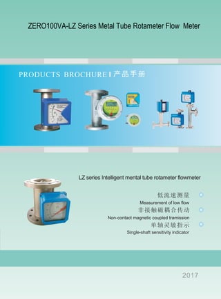
- 1. PRODUCTS BROCHURE LZ series Intelligent mental tube rotameter flowmeter Measurement of low flow Single-shaft sensitivity indicator Non-contact magnetic coupled tramission 2017 ZERO100VA-LZ Series Metal Tube Rotameter Flow Meter
- 2. (LZ ) Five Reaserongs High-class manufacture equipment Deport and stable quality Professional track and service No troble about installation and running Demarcate which was performed using actually flu- id before leaving the factory
- 3. Contents LZ series Intelligent metal tube rotameter Flowmeter 02 03 03 04 05 07 08 09 10 11 15 19 23 27 28 32 、 02 Contents 03 Product characteristic of Intelligent metal tube rotameter Flowmeter 03 Introduction of Intelligent metal tube rotameter Flowmeter 04 Typical application of Intelligent metal tube rotameter Flowmeter 05 Advantages of Intelligent metal tube rotameter Flowmeter 07 Technical parameters 08 Stucturel composition 09 Type and specification codes 10 Accessories with the instrument 11 Installation and Notices 15 Overall dimensions and weight 19 Explanations on indicators 23 Calclation meter size,rotator No.and scale 27 Flow table 28 Operation principle 32 Appendix
- 4. ( )LZ LZ series Intelligenti metal tube rotameter Accessories with the instrument , , Small volume, large flow range, convenient operation , ;16 ; , , , :10 1 , , , , , , Can be used in flammable, explosive and dangerous situations , , Multi-parameter calibration function , Reliable operation, small maintenance work loads and long life low straight pipe condition required and wide twrn-down10:1 Select the mode of measurement by the different require of the consumer Indicator of the intelligent flowmeter which have intellectual Property Suitable to measurement of flow quantity of low velocity and small diameter media Double line large liquid crystal display, displaying instantaneous flow quantity and accumulated flow quantity simultaneously, can be equipped with back light Single axis sensitive indication and Driving by non contact magnetic coupling Whole metal structure, suitable for high temperature, high pressure and strongly corrosive media Such power supply patterns as two-wire system, battery and AC for selection Having the function of data recovery,data backup and power failure protection
- 5. Introduction 。 , , 。 , 。 。 , , ; , 。 16 The metal tube ratometer flowmeter is a kind of variable area flow quantity measuring instrument. It has such features as small volume, large detection range and convenient operation. It is especially suitable to measure flow quantity of media with small flow velocity and small flow quantity. Intelligentized metal tube rotameters have field indication type and intelligentized remote transmission type. So it provides the customers with very wide selection spaces. In addition, advanced 16 bits micro processor and high quality industrialized components are adopted in the instrument, which ensures excellent performances of the flowmeter in various kinds of application situations. Type Application , , , , , , , , 。 Over the past years, metal tube rotameter Flowmeter is widely applied in the industries such as petrochemical, steel, power, metallurgy, light industry , food , pharmacy and water treatment, due to its superior performances and satisfactory performance- price.
- 6. LZ LZ Advantages of LZ series intelligent metal tube rotameter flowmeter LZ , , , 。 : , , 。 LZ 0.07 。 。 , 。 。 。 , , , 。 LZ 0-50000 0-99999999 , , , , , 。 , 。 , , , , 。 , , 。LZ LZ DN15-DN100 DN8 DN10 DN150 DN200: : , , , 。 。 LZ A1NiCo 500 450 LZ 16MP , , 。 , , 。 。 LZ IP65 LZ, , 。 , , 。 Lz : , , , , , 。 LZ 24VCD 220VAC、 , , , , , 。 LZ 16 MCU, , 。 , , 。11 Hart , Hart
- 7. 6 Double indication system The magnetic coupling principle is adopted in adopted in LZ series intelligent metal tube rotameters flowmeter and the instantaneous flow quantity is indicated through mechanical transmission . At the same time, the sensing magnet steel is driven to convert the magnetic signal corresponding to the flow signal into digital signal through electrons and the instantaneous and accumulated flow quantity are displayed through liquid crystal display. Advantages of such pattern are that: once there are faults in the electronic part, independent mechanical indication system can still reflect the field flow quantity, so that the reliability of the instrument is improved. Separation of magnetic coupling and magnetic signals Independent magnetic coupling system is adopted for LZ intelligent metal tube rotameter. Signals of its transmission part come from special sensing magnetic steels. Advantages of such are that it will not be affected by temperature of media and ferromagnet particles in measurement. In addition, it will not be affected by the size of bore diameter. Fixed distance is kept between sensing magnetic steels and the magnetic resistance transducer, So it can be ensured that every instrument with different bore diameter can have enough magnetic signals and high resolution can be brought, which can 0.07º At the same time, it can bring high precision. Double line liquid crystal digital display screen is adopted for LZ intelligent metal tube rotameter flowmeter. It will display instantaneous flow quantity and accumulated flow quantity simultaneously. The display range of instantaneous flow quantity is 0- 50000 and the display range of accumulated value is 0-99999999. It will reset automatically and the decimal points can be selected randomly. In addition, wide temperature liquid crystal is adopted for the liquid crystal screen. During the running of the instrument, the liquid crystal screen can be hot-plugged and the normal operation of the instrument will not be affected . When the liquid crystal screen is hot-plugged,the instrument can run normally. In addition, LZ intelligent metal tube rotameter also has the battery power supply type product. The electric quantity display stripe of the battery is similarly clear to that of the electric quantity of mobile phones. LZ intelligent metal tube rotameter flowmeter can provide all bore diameter from normal bore diameter DN15-DN100 to special bore diameter DN8.DN10-DN150.DN200 which can be reached by metal rotameter. Flowmeter it has special advantages in measuring small flow quantity. AINico excellent magnetic steels are adopted for the coupling magnetic steels or magnetic steels of rotator of the LZ intelligent metal tube rotameter. The demagnetization temperature is above 500 , so it can be used in 450 of high temperature media. As the coupling principle is adopted, the metal tube rotameter belongs to no leakage flowmeter and press doesn't have effect on the flowmeter, so the LZ intelligent metal tube rotameter can bear the pressure above 16MPa. ℃ ℃ Aluminum casting shell is adopted for the LZ intelligent metal tube rotameter and the protection level reaches up to IP65, so it can be used in the outdoor open situations. In addition, the LZ intelligent metal tube rotameter flowmeter. has two types such as intrinsic safety type and explosion proofing type and both of them obtain the national grade explosion proofing certification. LZ intelligent metal tube rotameter flowmeter provides the customer with comprehensive installation patterns: down in up out, down in up horizontal out, down horizontal in up out, right in left out, left in fight out and up in down out. Double line liquid crystal digital display Bore diameter of the measuring tube of the flowmeter is complete Resistance to high temperature and high pressure Good protection and explosion proofing performance Full series of installation pattern The LZ intelligent metal tube rotameter flowmeter can provide such power supply patterns as 24VDC two or three- wires power supply,220VACpower supply and battery power supply. It can also be equipped with back light. High power lithium batteries are adopted for batteries and one battery can be used for the instrument above three years. 16 bits MCU developed by U.S recently is adopted for the LZ intelligent metal tube rotameter flowmeter and it is equipped with highly integrated paster, so the product has high reliability. Various kinds of power supply patterns Highly integrated circuit Systematical software function and standard Hart communication pattern The instrument is calibrated by adopting the 11-point software to ensure the precision of the instrument to be calibrated. In addition, the Hart communication pattern can be optional for selection.
- 8. Main technical parameters of LZ series intelligent metal tube rotameter flowmeter Measurement range ℃(water)(20 ):1-200000l/h ℃, Mpa): ~ m /h(air)(20 0.1013 0.03 4000 ³ Ratio of range ,10:1 20:1 10:1 for standard type 20:1 for special type, Precision degree 1.5 1.0 standard type 1.5 grade, special type 1.0 grade Special standard (standard type):DN15-DN50 4.0MPa (special grade):DN15-DN50 25MPa ,1.6MPa The pressure grade of the flowmeter with the jacket is 1.6MPa and it should be agreed with the plant for special type before selection and ordering Pressure loss 7KPa-70KPa Media temperature ℃~ ℃,PTFE: ℃~ ℃(standard type):-40 100 0 120 (High temperature type): ℃~ ℃100 450 DN :η<5mPa.s(F -F )15 15.1 15.3 DN :η<30mPa.s25 η< mPa.s(F -F )30 15.4 15.8 DN -DN :<η< mPa.s50 150 30 Environment temperature : ℃~ ℃( ) - ℃~ ℃40 185 30 80 (Connection pattern) / NPT , M *1 2 20 1.5 Power supply :24VDC 4-20mA(12VDC-32VDC) Standard type: 24VD(two wires system 4-20mA(12VDC-32VDC) :24VDC 4-20mA(18VDC-28VDC) Alarm type: 24VDCthree wires system 4-20mA(18VDC-28VDC) :85-265VAC 50Hz Ac type: 85-265VAC 50Hz : , ,3.6V 7.5AH Battery type:3.6V,7.5AH lithium battery, can be used continuously for three years Load characteristic Ω Ω(two-wire system):RLmax=50*(-12) =600 @24V : Ω200 AC type:maximum load resistance is 200Ω long transmission type: 40 185 (liquiid crystal will not be damaged),- ℃~ ℃ normal operation temperature of liquid crystal is 30 80- ℃~ ℃ ( - ℃~ ℃Field pointer type): 40 100 Standard type:DIN2501standard flange Media viscosity Special type random standard flanges or screw threads appointed by the customers Cable interface 1/2NPT internal thread for explosion proof type and M20*1.5 internal thread for other types : Ω200 Alarm type:maximum load resistance is 200Ω Alarm output Upper limit or lower limit instantaneous flow quantity alarm Relay outputSwitching value alarm Liquid crystal display : - ( )0 50000 Range of instantaneous flow quantity display value:0-50000(may include decimal) :0-99999999( ) Range of accumulated flow quantity display value:0-99999999(may include decimal),automatic reset Protection level Ip65 :DIN2501
- 9. Structural composition of LZ series intelligent metal tube totameter flowmeter , : 。 , , , 。 , , , 。 。 , , , , 。 JB/T6844-1993 The series of metal tube rotameters flowmeter comply with National standard JB/T6844-1993 of China and they mainly consist of two parts: measuring tube and indicators. The measuring tube includes cone-shaped tube , guide apparatus, retainer and rotor. The indicator includes such components as magnetic servo system, pointer, scale plate and circuit. They are divided into field type and intelligent type. For the field type,rotation is generated by coupling of servo magnetic steels in the field indicator and magnetic steel in the rotor. At the same time, it drives the pointer to indicate flow quantity through the scale plate. , , 。 。 , , , , , , , 。 A/D D/A LCD For intelligent type, rotation is generated by coupling of servo magnetic steels in the intelligent type indicator and magnetic steels. At the same time, sensing magnetic steels and the pointer are driven.The instantaneous flow quantity and accumulated flow quantity are displayed through A/D transformation, digital filtering, temperature compensation, treatment of micro processor, D/A output and LCD liquid crystal display.
- 10. LZ Accessories of seriesintelligent metal tube rotameter flowmeter , : ( , , ) The instrument has been packed perfectly before leaving the factory and accessories with the instrument include: Specification Qualification certificate Packing list Other accessories (such as companion flange, magnetic filter, straight tube)
- 11. Installation of LZ series intelligent metal tube rotameter flowmeter : ,5XDN 250 100 Where:5xDN and 250 are the straight tube section in the front and rear of the flowmeter,100 is the pre-left position for installation of magnetic filter
- 12. Where:5xDN and 250 are the straight tube section in the front and rear of the flowmeter,100 is the pre-left position for installation of magnetic filter : ,5XDN 250 100
- 13. Notices on installation instrument , , 。 , 。 , 。 , 。 , 。 , 。 , , 2 , , 2 。 。 。 5 , 250。 , 。 10 。 , 。 , , , , 。 , , 。 PTFE , 。 PTFE 。 。 , , 。 , 。 Before installation of the instrument, the process lines should be blown off to prevent ferromagnetic substances staying in pipes from adhering in the instrument to affect performances of the instrument or even damage the instrument. If it is unavoidable, a magnetic filter should be installed before the entrance of the instrument. The instrument itself doesn t take part in the blowing off to avoid damage of the instrument. ' Before the instrument is installed in the process lines, all packing should be unpacked to check whether there are damages by transportation. In addition, the shell should be dismantled to take out the filler fixing pointers. The installation patterns of the instrument are divided into vertical installation and horizontal installation. If the vertical installation pattern is adopted, it should be ensured that the included angle between the central vertical line of the instrument and the plumb line should be smaller than2º. If the horizontal installation pattern is adopted, it should be ensured that the included angle between the horizontally central line of the instrument and the horizontal line should be smaller than2º Upstream and downstream pipes of the instrument should have the same bore diameter with the instrument. The connection flanges or screw threads should be matched. It should be ensured that the length of straight tube at the upstream of the instrument should be 5 times of the bore diameter of the instrument (5D) and the length of straight tube at the downstream of the instrument should not be smaller than 250. As signals are transmitted through magnetic coupling in the instrument, it is not permitted for ferromagnetic substances to exist within at least ten meters around the installation place in order to ensure the performances of the instrument. The instrument which is used to measure flow quantity of gases is calibrated under special pressure. If the gases are discharged to atmosphere directly at the outlet of the instrument, then pressure drop will be generated at the rotor and data distortion will be caused. If such operation conditions happen, then a valve should be installed at the outlet of the instrument. Instruments installed in pipes should not be affected by stress and there should have proper pipe support at the inlet and outlet of the instrument so that to make the instrument to locate in the minimum stress state. It should be especially careful in installing the instrument with PTFE liner. As PTFE will deform under the function of pressure, bolts of the flanges should not be tightened too severely. For the instrument with LCD, it should avoid that sunshine irradiates the display directly in the installation so that avoid decreasing of use life of the liquid crystal. When measuring low temperature media, the clamped type flowmeter should be selected.
- 14. : Overall dimensions and weight and pressure loss table of the standard type FA FAtype Overall dimensions and weight and pressure loss table of the standard type 50 M2 M1( ) 50 M4 Installation of M2 indicator for 50 type Installation of M4 indicator for 50 type (M1 indicator is the same) Overall dimensions and weight and pressure loss table of the clamped type 50 Overall dimension of 50 clamped type specification 50/T Overall dimensions,weight and pressure Overall dimensions,weight and pressure loss of 50 standard type loss of 50 standard type Symbol DN15 DN25 A1 A3 A A2 △PG1 220 241 14 135 155 195 225 250 150 140 120 110 100 6.5 10.5 14 19 23 33 42 60 70 5.2 3.7 8.7 14.2 15.2 33.7 48.7 280 300 330 350 405 460 230 255 270 280 320 350 DN50 DN80 DN100 DN150 DN200 G2 20 21 : G1 G1(kg) △P △P(KPa) DN200 350mm is the weight of the instrument(kg) is the pressure loss the installation height of DN200 is 350mm G2 G2 : (kg) is the weight of the instrument(kg)
- 15. Overall dimensions of LZ series intelligent metal tube rotameter flowmeter PTFE Overall dimensions and weight of flowmeter with PTFE Line Overall dimensions and weight and pressure loss table of the sanitary type polished tube PTFE Overall dimension of measuring tube with PTFE liner Specification 50/RP Overall dimensions and weight of 50/RP type Symbol A1 A7 G3 DN15 DN25 DN50 DN80 DN100 220 230 235 270 260 135 155 195 225 250 17.5 16.5 11 7.5 6 Specification 50/RW Overall dimensions and weight of 50/RW type Symbol A1 A7 G3 DN15 DN25 DN50 DN80 DN100 190 200 215 230 240 14 19 23 33 42 8.1 7.2 4.8 3.5 2.4 : (G kg)3 G is the weight of the instrument(kg)3 : (G kg)4 G is the weight of the instrument(kg)4 △ (P KPa) △P is the pressure loss(KPa)
- 16. FB Overall dimensions and weight and pressure loss table of FB type FC Overall dimensions and weight and pressure loss table of FC type 51 (type):DN15-DN200 52 type):DN15-DN200( Specification 51 Overall dimensions and weight of 51 type Symbol DN15 DN25 DN80 DN50 DN100 DN150 DN200 H(mm) L(mm) A(mm) G5 △P 560 260 120 120 120 150 150 150 200 260 260 260 260 300 300 560 600 700 700 760 800 7 18 22 228 36 45 58 70 8 15 25 29 50 61 Specification 52 Overall dimensions and weight of 52 type Symbol DN15 DN25 DN80 DN50 DN100 DN150 DN200 H(mm) L(mm) A(mm) G5 △P 500 250 120 120 120 150 150 180 200 250 250 300 300 350 400 500 650 800 800 850 880 5 20 28 33 45 53 63 70 8 14 31 50 67 81 : (G kg)4 G is the weight of the instrument(kg)4 △ (P KPa) △P is the pressure loss(KPa) : (G kg)5 G is the weight of the instrument(kg)5 △ (P KPa) △P is the pressure loss(KPa)
- 17. FDR Overall dimensions and weight and pressure loss table of FDR type Specification 53/PP Overall dimensions and weight of 53/PP type Symbol Symbol DN15 DN50 DN80 DN100 DN25 H(mm) G (kg)7 △P △PH(mm) L(mm) G (kg)8 430 450 6.5 10.5 30 540 557 570 400 400 250 21 32 48 50 45 40 35 : (G kg)7 G is the weight of the instrument(kg)7 △ (P KPa) △P is the pressure loss(KPa) : (G kg)8 G is the weight of the instrument(kg)8 △ (P KPa) △P is the pressure loss(KPa)
- 18. FDL Overall dimensions and weight and pressure loss table of FDL type 54 M2 (M1 ) Installation of M2 indicator for 54type(M1 indicator is the same) 54 M4 Installation of M4 indicator for 54type Specification 54 Overall dimensions and weight of 54 type Symbol DN15 DN25 DN50 DN80 DN100 DN150 DN200 A1 A2 220 211 280 300 330 350 405 460 230 255 270 280 320 350 G9 3.7 5.2 8.7 14.2 15.2 33.7 48.7 △P 14 19 23 33 42 60 70 : (G kg)8 G is the weight of the instrument(kg)8 △ (P KPa) △P is the pressure loss(KPa) DN200 350mm the installation height of DN200 is 350mm
- 19. Explanations on indicators M1、M2、M4 。 M1 ,M2 , ,M4 , 。 It mainly has three types of indicators such as M1, M2 and M4 for customers choose. M4 is mechanical type of flow indicator for local instantaneous display by pointer indication only; M2 is used for remote type of flow indicator which suitable to the situation of Expplosion suppressnor and intrinsic safely; M4 is multi-function type of flow indicator. Three kinds of indicators cooperate with different measuring tubes to compose diverse metal tube rotameter flowmeter. M1 ⑴ M1 , , , , 。 , 。 M1 Outing drawing of M1 type indicator (2) M1 SJ3.5 . . , , ;SJ3.5 WE77/EX-1 WE77/EX-2 . , . iaIICT5, WE77/EX-1 SJ3.5 , ,WE77/EX-2 SJ3.5 , . M1 type indicator (1) Mechanical Flow Indicator untilizes the rotator in the metering tube to rotate the following magnet with pointer cylinder, and then flow value can be indicated on the scale directly. Therefore it has simple structure, high reliable performance and needs no calibration. Two different media of scales can be drawn out under the requirements of users. (2) Limit alarming device In M1 indicator, SJ3.5type initiator and aluminum plate compose the limit alarming device. The initiator is installed at the position which can be cut by the aluminum plate which can be driven by the pointer axis. The alarming limit can be set randomly by changing the position of aluminum plate. Long transmission of upper and lower limit alarming signal can be realized through cooperative use of SJ3.5 type initator with transistor relay WE77/EX-1 and WE77-2/EX-2. In addition, it has intrinsically safe explosive proofing function. The explosive symbol is ia_CT5, in which WE77/EX-1 can cooperate with one SJ3.5 initiator to realize one alarming limit and WE77/EX-2 can cooperate with two SJ3.5 initiators to realize upper and lower limit alarms.
- 20. (3)WE77 SJ3.5 Technical parameters of WE77 transistor and SJ3.5 initiator ( ) , :4 WE77 Type WE77/EX-1 WE77/EX-2 Operation state Terminal state closed circuit current loop 4-5 3-4 3-4 2-3 6-7 7-8 、 、Open circuit current loop ( )4 WE77 transistor relay is generally connected to the normal open operation pattern, and it can also be changed into normal off operation pattern through jumper. The jumper patterns are as shown in the following table: Type WE77/EX-1 WE77/EX-2 Power supply 220VAC 24VDC、 Power supply 3.5VA about 3.5VAPower consumption Operation temperature -25 -+60℃ ℃ Open circuit voltage 8(13.5)V 8(13.5)V Short circuit current 8(31)mA 8(62)mA Permissible capacitance 3(31)mH 1(7.6)mH Permissible capacitance 230(609)nF 160(539)nF Type SJ3.5-N SJ3.5-SN Power supply 8VDC 8VDC Effective area on ≥3mADC Effective area off ≤1mADC ≤1mADC Self inductance 250 Hμ 100 Hμ Self capacitance 50nF 60nF Operation temperature -25 -+70℃ ℃ -40 -+100℃ ℃
- 21. (5)SJ3.5 WE77/ :( ) ( ) ( ) ( ) ( )1 SJ3.5 2 WE77/Ex 3 4 5 WE77/Ex wiring of SJ3.5 initiator and WE77/EX transistor relay Where:(1)SJ3.5 initiator; (2)WE77/Ex; (3)Operation indicator light of relay; (4)Output of relay; (5)Power supply of WE77/Ex (6)WE77/EX Installation of WE77/EX trasistor relay and outline drawing
- 22. M2 M4 ⑴ , , 。 , , , , , , , 。 M2 CPD iaIICT5 4-20MA ⑵ M2 M1 M2 / / PLC , , , , , , , , 。 ⑶ , , , 。 , 。 M2 ⑷ , @ , , , , ℃ , , 。 M2 3.6V 7.5AH 10-45 M2 indicator M4 indicator (1) M2 indicator is as shown in the figure. The shell is a square and a CPD type intelligent circuit plate is built in the metal shell. It is intrinsically safe design and the explosive proof symbol is ia ll CT5.It not only has independently mechanical pointer to indicate instantaneous flow quantity, but also has five bits liquid crystal to digitally display instantaneous flow quantity and eight bits digitally display accumulated flow quantity. It is also equipped with panel operation and human-machine icterface. It can also output many kinds of signals such as 4-20mA current signals, upper and lower limit alarm. (2) Alarming patterns: the upper and lower alarming patterns of M2 indicator are different from those of M1.Relay output is adopted for M2 indicator. The switch alarming limit is not set mechanically but by adopting keyboard operation. This pattern is flexible and convenient, but also it is accurate and reliable. In addition, it has the function of power failure protection. It also has the logic function and the alarming output can be set in the software for upper/lower limit without jumper. It can be connected to PLC through intermediate relay or safety barrier. (3) M2 indicator also has such functions as multi-parameter calibration, setting function, data backup, data recover and power failure protection. In addition, the liquid crystal back light display function can be selected if it is not under the power supply of two-wire system. (4) Battery type: battery power supply can be realized for M2. It adopts one 3.6V @7.5H high power lithium battery to supply power and it can operate continuously for three years. There is an electric quantity display bar at the low right of the liquid crystal display to remind the customer of replacing the battery on time. In addition, the efficiency of the battery is the highest in the range of 10-45 . In this range, the discharging is table and operation time is extended.℃ M4 indicator contains all functions of M1, M2 and M3 indicators and an independent pointer indication system is installed in it.
- 23. Calculation of diameter, rotor No. and scale ( ) , Qs:1 : - ( ) ( , )Qs 20 0.1013MPa Q - K - ( ) , , 。 2 Qs ( ) , :3 Q :Qi 。 ( )4 , , Calculation method (1) According to data provided by the customers,proper equations are selected to calculate the flow quantity of corresponding calibrating media Qs: Where :Qs-flow quantity of the calibrating media (water or air)under standard state(20,0.1013MPa) Q- Flow quantity of customers’edia K-correction coefficient (2) According to the Qs value obtained from calculation, the rotor No. and diameter of the measuring tube are determined by vonsulting the flow table. The values in the flow table are the flow quantity of water or air under standard states. (3) After diameter of the measuring tube and rotor No. are determined, it is suggested that the following equation is used to determine the upper limit Q of the flow scale of the measured media: Where: Qi-maximum of flow quantity of water or air corresponded by rotor No. which is selected by consulting the flow table. (4) As correction of viscosity is not considered in the calculation, there might have differences between the result and that calculated in the plant, please under this situation.
- 24. K (1) (a) Q K: (b) Q K : ( )ρs g/m3 7.8 ( )PTFE 3.4 Hastelloy 8.3( ) ρ: Caclculation of the correction coefficient K (1) For liquid media (a) If Q provided by the customer is volu me flow of liquid,then following equation is used to calculate K: (b) If Q provided by the customer is mass flow of liquid, then following equation is used to calculate K: Where density of selected rotor (kg/ m )ρ :s 3 Density of stainless steel rotor is 7.8 Density of (PTFE) rotor is 3.4 Density of Ni-based alloy(Hastelloy) is 8.3 :Density of measured mediaρ
- 25. (a) Q 20 0.1013MPa) K:( ℃, , (b) Q K, : (c) Q K, : :ρ: (Kg/m ) 3 P: (MPa) P: (K) ρ : (1.205Kg/m )0 3 P : (0.1013MPa)0 T : (293.15)0 (d) : :ρst: (Kg/m ) 3 ρ : (Kg/m )t 3 T : (K)t T : (K)0 p : (MPa)t p : (MPa)0
- 26. Ror gas media (a) If Q provided by the customer is volume flow of gas under standard state(20 0.1013MPa), then following equation is used to calculate K: ℃, (b) If Q provided by the customer is volume flow of gas under operation conditions, then following equation is used to calculate K: (c) If Q provided by the customer is mass flow of gas, then following equation is used to calculate k: In above equations: ρ:Density of gas media to be measured under standard condition(Kg/m )3 ρst:Density of gas media to be measured under standard condition(Kg/m ) 3 ρt:Density of gas media to be measured under operation conditions(Kg/m ) 3 T Absolute temperature of gas media to be measured under operation conditions(K)t: T Absolute temperature of gas media to be measured under standard conditions(K)0: P Absolute Pressure of gas media to be measured under operation conditions(MPa)t: P Absolute Pressure of gas media to be measured under standard conditions(MPa)0: P Absolute Pressure of calibrating Media(0.1013MPa)0: P:Absolute pressure of gas media to be measured(MPa) T:Absolute temperature of gas media to be measured(K) ρ0:Density of air under standard conditions(1.205Kg/m )3 T Absolute temperature of calibrating Media(293.15)0: (d) Conversion equation of auxiliary density: Where:
- 27. Flow table (L/h)water(L/h) Air Nominal bore Rotator No. RO,R1,R2,Ti,RL Material RO,R1,R2,Ti,RL PTFE Material PTFE Nm /h( )3 Nm /h(under standard state) 3 F15.0 F15.1 F15.2 F15.3 F15.4 F15.5 F15.6 F15.7 F15.8 F15.9 F25.0 DN15 1 10~ 6 16~ 2.5 25~ 4.0 40~ 6.3 63~ 10 100~ 16 160~ 25 250~ 40 400~ 63 630~ 63 630~ 1.6 16~ 2.5 25~ 4.0 40~ 6.0 60~ 10 100~ 16 160~ 25 250~ 40 400~ 0.03 0.3 0.05 0.5 0.07 0.7 0.11 1.1 0.18 1.8 0.28 2.8 0.4 4 0.7 7 1.0 10 1.6 16 3.0 30 ~ ~ ~ ~ ~ ~ ~ ~ ~ ~ ~ F25.1 F25.2 F25.3 F25.4 F25.5 100 1000~ 160 1600~ 200 2000~ 250 2500~ 320 3200~ 63 630~ 100 1000~ 160 1600~ 3.0 30 4.5 45 7.0 70 ~ ~ ~ DN25 DN50 DN80 DN100 DN150 DN200 F25.6 F25.7 F25.8 F50.0 F50.1 F50.2 F50.3 F50.4 F50.5 F80.0 F80.1 400 4000~ 500 5000~ 630 6300~ 500 5000~ 630 6300~ 1000 10000~ 1600 16000~ 2000 20000~ 2500 25000~ 1600 16000~ 2000 20000~ 200 2000~ 250 2500~ 320 3200~ 400 4000~ 630 6300~ 1000 10000~ 1600 16000~ 12 120 18 180 18 180 25 250 40 400 63 630 ~ ~ ~ ~ ~ ~ F80.2 F80.3 F80.4 F100.0 2500 25000~ 4000 40000~ 6300 63000~ 4000 40000~ 1600 16000 2500 25000 4000 40000 ~ ~ ~ 70 700 120 1200 180 1800 ~ ~ ~ F100.1 F100.2 F100.3 F150.0 6300 630000~ 8000 80000~ 1000 10000~ 8000 80000~ 4000 40000 6000 60000 8000 80000 ~ ~ ~ 180 1800 300 3000 ~ ~ F150.1 F150.2 F200.0 10000 100000~ 15000 150000~ 15000 150000~ 8000 80000~ 300 3000~ F200.1 20000 200000~ 。 DN20,DN32,DN40,D65,DN125, It can be DN20,DN32,DN40 for special bore DN65,DN125, please contact and consultant with the manufacturer
- 28. Operation principle 1 , 2( )。 , 。 , : , ; , 。 , 。 , , 。 , , 。 。 , 。 。 Vf ,Af ,pf ,p 。 1-1 , 2-2 , (P1-P2)。 , = : : : (2-1) (2-2) , , Vf,Af,P , (P1-P2) , 。 , :A -- ,m ; C -- 、 、 Re , 。 Re> ,C R R R 2 104 0.98
- 29. 。 , , , 。 。 。 。 ( ) , , , , , , 。 , , 。 CR AR 2-3 d (2-3) ( m ): 2 (2-4) (2-5) : ( )d- :m h- m, : -β a.b- 。 , 。 , 。 CR , 。 1-69, , : 1 ; 2 。 。 , : pg , : g ; g 。1 2
- 30. (2-1) (2-2) (2-3) (unit:m ) 2 The structure of a rotameter is that a rotor 2( or called as floater )made from metal or other materials which can rotate freely is installed in a vertical cone-shaped metal tube 1 whose sectional area is increased gradually from down to up. The fluid to be measured enters from the bottom of the metal tube and effluent from the top. When the fluid flows upwards through the vertical cone-shaped tube, the rotor is affected by two forces: one is the driving force vertically upwards, it is equal to pressure difference generated by that the fluid flows upward through the annular section between the rotor and the cone-shaped tube; the other is vertically downwards net gravity, it is equal to the difference between the gravity encountered by the rotor and the float force of the fluid on the rotor. When the flow quantity is increased to make that the pressure difference is larger than the net gravity of the rotor, the rotor will rise. When the pressure difference is equal to the net gravity, the rotor will stay in a certain position. There are scales on the external surface of the metal tube and the flow quantity of measured fluid can be read according to the staying position of the rotor. The rotameter is a variable area and constant pressure difference flowmeter. The pressure difference acting on upstream and downstream of the rotor is a constant value while the annular section area between the rotor and the cone-shaped tube changes with flow quantity. The position of the rotor in the cone-shaped tube reflects the value of flow quantity. If it is assumed that Vf is the volume of the rotor, Af is the sectional area of the largest part of the rotor, _f is the density of the rotor material and _is the density of measured fluid. If the annular section at the upstream is 1-1 and the annular section at the downstream is 2-2 , then the pressure difference generated by flowing of the fluid through the annular section is (p1-p2). When the rotor is in equilibrium state in the fluid. ' ' Then: Therefore It can be seen from the above equation that Vf, Af, f and are constant when a fixed rotor is used to measure the flow quantity of one fluid, therefor (p1-p2) is also constant and it is unrelated to the flow quantity Referring to the formula of flow quantity for orifice plate flowmeter, the formula of flow quantity for rotameter canbe obtained, that is : ρ ρ Where: AR--annular sectional area between the rotor and metal tube m²; CR--flow coefficient of rotameter, zero dimension, it is relatedtothe Re value and the shape of rotor, it can be obtained from experimental measurement or related instrument manuals. When the Re between the annular gap.104,CR may be selected as 0.98. The relation between the circulating annular area and the height of the rotor is as shown in equation (2-3).When the structural design is determined, then d and are constant. Generally the second order nonlinear relation can not be ignored for quadratic terms in the equation. Only when the cone angle is very small can it be regarded as approximate linearity. It can be known from the above equation that for one rotameter, if the flow coefficient CR is a constant in the measured flow quantity range, then the flow quantity only changes with the annular sectional area AR. As the metal tube is a cone, the annular sectional area will change with the position of the rotor, therefore the height of the position located by the rotor can be used to reflect the value of flow quantity.
- 31. (2-5) (2-4) Where: d-maximum diameter of the rotor(that is operation diameter) h-lifting height of the rotor from the place where the internal diameter of the cone shaped tube is equal to the maximum diameter of the rotor, unit: m -one angle of the cone shaped tube a , b-constant β Calibration of the scale of the rotameter The scale of rotameter is related to the density of measure fluid. Before the rotameter leaves the factory, water and air are generally used as the media for calibrating the scale of the rotameter. When the rotameter is used to measure other fluids, original scales should be calibrated If the flow coefficient CR of the used liquid in calibration at leaving the factory is equal to that of the liquid in actual operation and the effects of change of viscosity are ignored, then according to equation 1-69, the relation between flow quantities of these two kinds of liquids at the same scale is : Where the subscript 1 represents the liquid used in calibration at leaving the factory; subscript 2 represents the liquid in actual operation. In the similar way , the relation between flow quantities of two kinds of gases at the same scale is : As the density of the rotor material is much larger than the density g of any gases, above equation can be simplified as:ρ Where the subscript g1 represents the gas used in calibration at leaving the factory; subscrit g2 represents the gas in actual operation.
- 32. Appendixl Flange specification Density of normal gases Density of normal liquids ℃(Pressure): 0.1013MP (Temperature): 20 (unit): kg/m3 Name Density Name Density Name Density DensityName Air 1.2041 Propane 1.8332 Benzene 3.2476 Fluorine 1.5798 Nitrogen 1.1646 Normal butane 2.4163 Carbon monoxide 1.1650 Chlorine 2.9476 2.0990 Oxygen 1.3302 Iso-butane 2.4163 Carbon dioxide 1.8290 Chloromethane 2.6821 Helium 0.1664 Normal-pentane 2.9994 nitrogen monoside 1.2474 ethyl chloride 0.7080 Hydrogen 0.0838 Ethylene 1.1660 nitrogen dioxide 1.9121 Ammonia 5.7110 Hryton 3.4835 Prolylene 1.7495 nitrous oxide 1.8302 -11 freon-11 5.0269 Xenon 5.4582 -1 1-butene 2.3326 hydrogen sulphide 1.4169 -12 freon-12 4.3428 Neon 0.8391 -2 Syn-butane-2 2.3327 Hydrogen fluoride 1.1235 -13 -113 freon-13 freon-113 7.7900 Argon 1.6605 -2 Trans-butane-2 2.3327 carbon oxysulfide 2.4973 Methane 0.6669 Iso-butene 2.3327 Ozone 1.9952 Ethane 1.2500 Acetylene 1.0830 Sulfur dioxide 2.7260 ℃(temperature):20 (unit):kg/m3 Name Density Name Density Name Density DensityName Water 998.3 Ethanol 789.2 m-cresol 1034 Chloroform 1490 Mercury 13545 Ethylene glycol 1113 P-cresol 1011 carbon tetrachloride 1594 880 Bromine 3120 Normal propanol 804.4 methyl formate 975 o-xylene 864 Sulfuric acid 1834 Iso-propanol 785.1 methy propionate 915 m-xylene 861 Phosphoric acid 1512 n-butyl alcohol 809.6 Formic acid 1220 P-xylene 866 (30%) Hydrochloric acid 1193 Acetonitrile 783 Acetic acid 1049 Toluene 1081 Cyclobutane 1261 Normal pentanol 813 Propionic acid 993 o-chlorotoluene 1072 Acetone 791 Aldehyde 783 Aniline 1021 m-chlorotoluene Cyclohexane Hexane 778 660 684 702 Methylethyl ketone 803 Propionic aldehyde 808 Propionitrile 781.8 Phenol 1050 Cyclo-hexanone 946.6 Butyronitrile 790 Carbon bisulfide 1262 791.3 Diethylether 714 1261.3 1020 Thiophene 1065 1326 934 Heptane Ethanolamine Glycerol Methylene dichloride Octane methanol Orthocresol methyi acetate
- 33. Appendix2 the comparison list of flowrate and flow ★ 3m/s ★ /Flowrate of media is suitable to below 3m s inch(mm) (m/s) Attached(m s)/ (m /h) 3 flowrate(m /h)3 0.01 0.10 0.30 0.50 1.00 2.00 3.00 4.00 5.00 10.00 10 15 20 25 32 40 50 65 80 100 125 150 200 250 300 0.00283 0.00636 0.01131 0.01767 0.2895 0.04524 0.07069 0.11945 0.18096 0.28274 0.44178 0.63617 1.13097 1.76715 2.54469 0.02827 0.06362 0.11309 0.45239 0.70687 1.19459 1.80956 2.82743 4.41786 6.36173 11.3097 17.6715 25.4469 0.28953 0.17672 0.08482 0.19085 0.33929 0.53014 0.86859 1.35717 2.12058 3.58377 5.42867 8.4832 13.2536 19.0852 33.9292 53.0144 76.3407 0.14137 0.31807 0.56549 0.88357 1.44765 2.26195 3.53429 5.97295 9.04779 14.1372 22.0893 31.8086 56.5487 88.3573 127.235 0.28274 0.63617 1.13097 1.76715 2.89529 4.52389 7.06858 11.9459 18.0956 28.2743 44.1786 63.6173 113.097 176.715 254.469 0.56549 1.27235 2.26195 3.50429 5.79058 9.04779 14.1372 23.8918 36.0911 56.5487 88.3573 127.2345 226.195 353.429 508.938 0.84823 1.90852 3.39292 5.30144 8.68588 13.5717 21.2058 35.8377 54.2867 84.823 132.536 190.852 339.292 530.144 763.407 1.13097 2.54469 4.52389 7.06858 11.5812 18.0956 28.2743 47.7356 72.3823 113.097 176.715 254.469 452.389 706.585 1017.88 1.41372 3.18086 5.65487 14.4765 8.83573 22.6195 35.3429 59.7295 90.4779 141.372 220.893 318.086 565.487 883.573 1272.35 2.82743 6.36173 11.3097 17.6715 28.9529 45.2389 70.6858 119.459 190.956 282.743 441.786 636.173 1130.973 1767.15 2544.69
- 34. Appendix3 flange specification 1 normal flage specification、 2 high pressure flange specificootion Table、 HG20594-97 HG20594-97 PN25MPa normalHG20595-97 Normal HG20594-97 DN K d n 15 95 65 35 4 14 14 18 18 18 22 22 4 4 8 8 8 12 52 84 118 140 195 246 85 125 160 180 240 295 115 165 200 220 285 340 4.0 4.0 4.0 1.6 1.6 1.6 1.6 25 50 80 100 150 200 M12 M12 M16 M16 M16 M20 M20 ΦD ΦL Bolt Pressure PN25MPa DN15 DN25 DN40 DN50 DN80 DN100 DN125 DN150 DN200 130 150 185 200 255 300 340 390 485 400 320 275 235 150 105 90 46 26 18 18 48 3.2 3.6 5 6.3 11 14.2 16 17.5 25 60 84 95 136 164 242 305 206 32 45 57 102 127 159 180 244.5 22 26 26 30 33 33 36 42 60 65 80 85 102 120 140 160 190 2 4 3 6 8 10 10 12 14 16 18 25 3 3 3 3 3 3 3 3 4 4 8 8 8 12 12 12 2 2 2 2 2 2 2 2 28 34 38 46 54 60 68 82 65 84 99 132 156 184 211 284 135 200 M16 M20 M24 M24 M27 M30x2 M30x2 M33x2 M39x3 H n L R A1 N S Bolt
- 35. 、5 Appendix4 list of Flange specification HG20594-1997 HG20593-1997 HG20617-1997 HG20595-1997 GB/T9115.1-2000 GB/T9115.4-2000 GB/T9115.3-2000 GB/T9115.2-2000 JB/T82.2-1994(2005 ) JB/T82.1-1994(2005 ) JB/T82.4-1994(2005 ) ( ) ( ) ( ) ( ) 、 Appendix5 Manufacturing Standard and Inspection Criterion of Metal Tube Rotary Flowmeter GB/T 6844-93 JJB 257-94 GB/T 15464-1995 、
- 36. Appendix6 Overall dimensions of magnetic filter and straight tube straight tube magentic filer PTFE straight tube withPTFE lines PTEE filter withPTFE lines DN PN D K nxcd b H1 H2 15 95 65 45 75 250 250 250 250 250 250 125 250 400 500 750 4 14 4 14 4 18 4 18 4 18 4 23 68 102 138 162 212 85 125 160 180 240 115 165 200 220 285 25 50 80 100 150 4.0 4.0 4.0 1.6 1.6 1.6 : ,H1 H2 H1 is the length of straight tube in inlet H1 is the length of straight tube in outlet