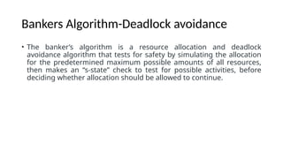
An operating system (OS) is a vital software component that acts as an intermediary between the user and the computer hardware, providing a structured environment in which applications can run efficiently and securely. It manages the hardware resources of a computer system, including the CPU, memory, storage devices, and input/output peripherals, ensuring that each application and process gets the resources it needs without interfering with others. One of its primary roles is process management, which involves creating, scheduling, and terminating processes, as well as handling inter-process communication and synchronization to maintain smooth multitasking. Another critical function is memory management, where the OS allocates and deallocates memory spaces as needed, keeping track of each byte in a computer’s memory and ensuring that no process accesses unauthorized areas, thus maintaining data integrity and system stability. In addition, the operating system handles file system management by organizing data into files and directories, providing access control, and managing storage devices, which allows users to store, retrieve, and manipulate data in an organized manner. Modern operating systems also include security features that protect data and system resources from unauthorized access, malware, and user errors, employing authentication mechanisms, access control lists, and encryption technologies. Furthermore, they provide a user interface—either graphical (GUI) or command-line (CLI)—that facilitates interaction between the user and the machine, making complex tasks simpler and more intuitive. There are several types of operating systems, such as batch operating systems, which process jobs in groups without user interaction; time-sharing systems, which enable multiple users to interact with a computer simultaneously; real-time operating systems, designed for applications requiring immediate responses, such as embedded systems and industrial robots; and distributed operating systems, which manage a group of distinct computers and present them as a single coherent system to the user. Examples of widely used operating systems include Microsoft Windows, which dominates the personal computer market with its user-friendly GUI; macOS, known for its sleek design and strong integration with Apple hardware; Linux, an open-source and highly customizable OS popular among developers and in server environments; and Android and iOS, which power most smartphones and tablets worldwide. As technology continues to evolve, operating systems are increasingly incorporating features like virtualization support, advanced power management, and AI-driven optimizations, reflecting the growing demands of cloud computing, mobile devices, and the Internet of Things (IoT). Ultimately, the operating system plays an indispensable role in bridging the gap between complex hardware operations and the user’s need for accessible, reliable, and efficient computing experiences.
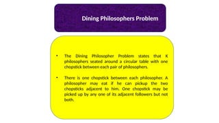
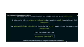

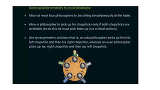
![Dining Philosophers Problem
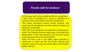
Void Philosopher
{
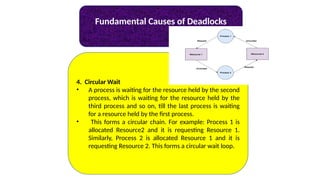
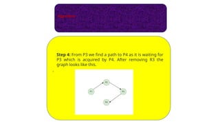
while(1)
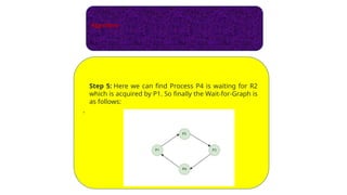
{
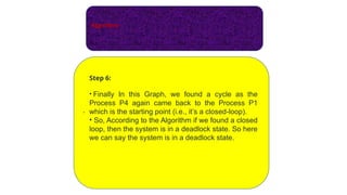
take_chopstick[i];
take_chopstick[ (i+1) % 5] ;
. .
. EATING THE NOODLE
.
put_chopstick[i] );
put_chopstick[ (i+1) % 5] ;
.
. THINKING
}](https://image.slidesharecdn.com/unit3-250628122848-ac44d95a/85/xxxxxxxxxxxxxxxxxxxxxxxxxxxxxxxxxxxxxxxxxxxxxxxxxxxxxxxxxxxxxxxxxxxxxxxxxxxx-20-320.jpg)
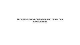
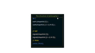
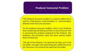
![Dining Philosophers Problem
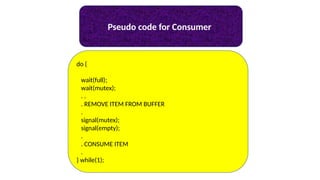
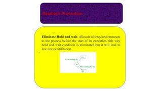
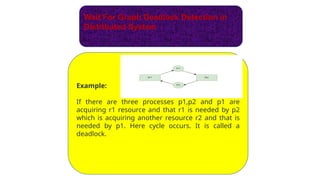
•Suppose Philosopher P0 wants to eat, it will enter in
Philosopher() function, and execute take_chopstick[i]; by
doing this it holds C0 chopstick after that it
execute take_chopstick[ (i+1) % 5]; by doing this it holds C1
chopstick( since i =0, therefore (0 + 1) % 5 = 1)
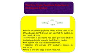
•Similarly suppose now Philosopher P1 wants to eat, it will
enter in Philosopher() function, and
execute take_chopstick[i]; by doing this it holds C1
chopstick after that it execute take_chopstick[ (i+1) %
5]; by doing this it holds C2 chopstick( since i =1, therefore
(1 + 1) % 5 = 2)
•But Practically Chopstick C1 is not available as it has
already been taken by philosopher P0, hence the above
code generates problems and produces race condition.](https://image.slidesharecdn.com/unit3-250628122848-ac44d95a/85/xxxxxxxxxxxxxxxxxxxxxxxxxxxxxxxxxxxxxxxxxxxxxxxxxxxxxxxxxxxxxxxxxxxxxxxxxxxx-21-320.jpg)
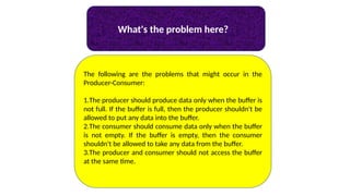
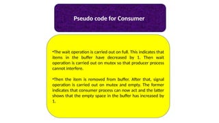


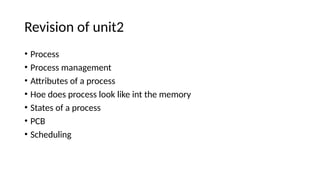
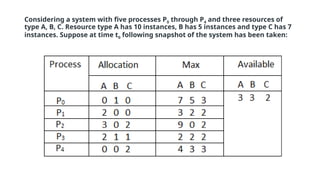
![• Available
It is a 1-d array of size ‘m’ indicating the number of available
resources of each type.
• Max
It is a 2-d array of size ‘n*m’ that defines the maximum
demand of each process in a system.
• Allocation
It is a 2-d array of size ‘n*m’ that defines the number of
resources of each type currently allocated to each process.
• Need
It is a 2-d array of size ‘n*m’ that indicates the remaining
resource need of each process.
Need [ i, j ] = Max [ i, j ] – Allocation [ i, j ]](https://image.slidesharecdn.com/unit3-250628122848-ac44d95a/85/xxxxxxxxxxxxxxxxxxxxxxxxxxxxxxxxxxxxxxxxxxxxxxxxxxxxxxxxxxxxxxxxxxxxxxxxxxxx-63-320.jpg)
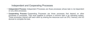
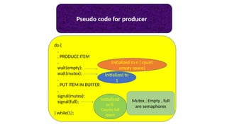
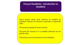
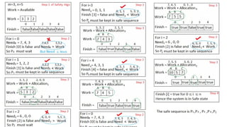
![Safety Algorithm
The algorithm for finding out whether or not a system is in a safe state
can be described as follows:
1) Let Work and Finish be vectors of length ‘m’ and ‘n’ respectively.
Initialize: Work = Available
Finish[i] = false; for i=1, 2, 3, 4….n
2) Find an i such that both
a) Finish[i] = false
b) Needi <= Work
if no such i exists goto step (4)
3) Work = Work + Allocation[i]
Finish[i] = true
goto step (2)
4) if Finish [i] = true for all i
then the system is in a safe state](https://image.slidesharecdn.com/unit3-250628122848-ac44d95a/85/xxxxxxxxxxxxxxxxxxxxxxxxxxxxxxxxxxxxxxxxxxxxxxxxxxxxxxxxxxxxxxxxxxxxxxxxxxxx-64-320.jpg)
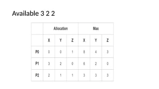
![• Need [i, j] = Max [i, j] – Allocation [i, j]
So, the content of Need Matrix is:](https://image.slidesharecdn.com/unit3-250628122848-ac44d95a/85/xxxxxxxxxxxxxxxxxxxxxxxxxxxxxxxxxxxxxxxxxxxxxxxxxxxxxxxxxxxxxxxxxxxxxxxxxxxx-66-320.jpg)


![Cs problem [repaired]](https://cdn.slidesharecdn.com/ss_thumbnails/csproblemrepaired-120307014039-phpapp01-thumbnail.jpg?width=640&height=640&fit=bounds)