WORKING CAST AND
WORKING CAST AND
DIES
DIES
CONTENTS
CONTENTS
DEFINITION – CAST , DIE
PREREQUISITES OF GOOD CAST
REQUIREMENTS OF A DIE
DIE MATERIALS – CLASSIFICATION
- METAL DIES
- STONE DIES
- ELECTRPLATED DIES
- CERAMIC DIES
- CEMENT DIES
- RESIN DIES
DIE HARDNER
DIE SYSTEMS – INDIVUAL DIES, REMOVABLE DIES ,
- PINDEX , DVA , GIROFORM , ACCUTRAC
CONCLUSION
REFERENCE
CAST
CAST
A life-size likeness of some desired form. It is formed
within or is a material poured into a matrix or
impression of the desired form (GPT-5) .
The working (or master) cast is the replica of the
prepared teeth, ridge areas, and other parts of the
dental arch.
CAST
CAST
The working cast is the cast that is mounted on an
articulator. To provide the most accurate articulation,
it normally should represent the entire arch.
- In the fabrication of the wax pattern, it is used to
establish Interproximal contacts, buccal and lingual
contours, and occlusion with the opposing teeth .
PREREQUISITES OF GOOD
CAST
CAST
1. It must reproduce both prepared and unprepared tooth surfaces.
2. The unprepared teeth immediately adjacent to the preparation
must be free of voids.
3. All surfaces of any teeth involved in anterior guidance and the
occlusal surfaces of all unprepared teeth must allow for precise
articulation of the opposing casts.
4. All relevant soft tissues should be reproduced in the working cast,
including all edentulous spaces and residual ridge contours that
will be involved in the fixed prosthesis .
DIE
DIE
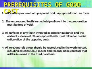
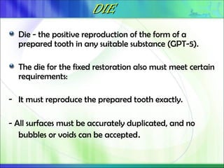
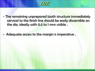
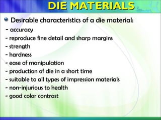
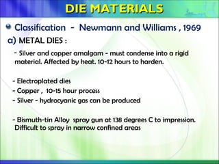
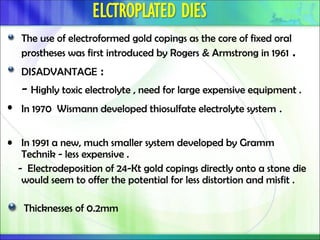
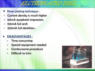
Die - the positive reproduction of the form of a
prepared tooth in any suitable substance (GPT-5).
The die for the fixed restoration also must meet certain
requirements:
- It must reproduce the prepared tooth exactly.
- All surfaces must be accurately duplicated, and no
bubbles or voids can be accepted.
DIE
DIE
- The remaining unprepared tooth structure immediately
cervical to the finish line should be easily discernible on
the die, ideally with 0.5 to 1 mm visible .
- Adequate access to the margin is imperative .
DIE MATERIALS
DIE MATERIALS
Desirable characteristics of a die material:
- accuracy
- reproduce fine detail and sharp margins
- strength
- hardness
- ease of manipulation
- production of die in a short time
- suitable to all types of impression materials
- non-injurious to health
- good color contrast
DIE MATERIALS
DIE MATERIALS
Classification - Newmann and Williams , 1969
a) METAL DIES :
- Silver and copper amalgam - must condense into a rigid
material. Affected by heat. 10-12 hours to harden.
- Electroplated dies
- Copper , 10-15 hour process
- Silver - hydrocyanic gas can be produced
- Bismuth-tin Alloy spray gun at 138 degrees C to impression.
Difficult to spray in narrow confined areas
The use of electroformed gold copings as the core of fixed oral
prostheses was first introduced by Rogers & Armstrong in 1961 .
DISADVANTAGE :
- Highly toxic electrolyte , need for large expensive equipment .
• In 1970 Wismann developed thiosulfate electrolyte system .
• In 1991 a new, much smaller system developed by Gramm
Technik - less expensive .
- Electrodeposition of 24-Kt gold copings directly onto a stone die
would seem to offer the potential for less distortion and misfit .
Thicknesses of 0.2mm
The areas to be plated are first coated with finely powdered
silver or graphite .
The impression is then placed in an electroplating bath .
A layer of pure metal is deposited on the impression and is
supported with Type IV stone or resin.
performed slowly – TYPICALLY TAKES 8 hrs .
silicone impression materials are difficult to electroplate evenly –
low surface energy .
Polyether - hydrophilic nature, imbibe water and become
distorted - cannot be plated accurately
Silver plating technique :
- Current density is much higher
- 60mA quadrant impression
- 150mA full arch
- 250mA full dentition .
• DISADVANTAGES :
- Time consuming
- Special equipment needed
- Combursome procedure
- Difficult to trim
STONE DIES :
- Type IV and Type V gypsum products .
- The materials are capable of reproducing a 20-um-wide line as
prescribed by ADA specification No. 19 .
- Setting and thermal expansion compensate for the casting
shrinkage .
- Gypsum's greatest disadvantage is its relatively poor resistance
to abrasion .
- To overcome this disadvantage - DIE HARDENER
Materials like colloidal silica , cyanoacrylate , gum arabic , calcium
hydroxide , polystyrene - added or coated to gypsum to improve
abrasion resistance .
Methods- soaking or boiling dies , coating , air thinning , brush
thinning , shaking .
• Composition of a typical die hardener :
- Methyl Ethyl ketone or any solvent = 75%
acrylic resin or Methyl Methaacrylate = 25%
• Little effect on the hardness of the stone, they improve abrasion
resistance .
• Slight increase in setting expansion.
• Abrasion resistance most improved by impregnate the surface
of the die with a low-viscosity resin such as cyanoacrylate.
• increase in scratch resistance by 48% , increase abrasion
resistance by 150%.
• Abrasion resistance is improved by various mechanism :
- binding to gypsum matrix ( resin )
- filling subsurface voids .
- Sealing the gypsum surface .
Ceramic dies :
- Diamond die - expensive
- Ceramco Die - must use a separator to remove the porcelain or
removal of fired porcelain will be impossible without fracturing
the die.
Cement Dies :
- phosphate or polyacrylic acid bonded cements .
- they shrink slightly , brittle , tendency to crack – dehydration .
- Modle Kryptex - can be used with any impression material
Resin dies :
• Epoxy Resin- household and industrial adhesive .
- abrasion resistant, more than gypsum products .
- shrinkage during polymerisation ( 0-1% ) .
- detail reproduction is better.
- fit more tighter than those made on gypsum .
- polysulfide and hydrocolloid - not compatible .
• Diemet - is semi-solid and cannot be poured, must be pushed
into the impression.
• Self-cure resin - considerable shrinkage, unsuitable as a routine
die material.
• Polyurethane – polymerization shrinkage less .
Similar to Heavy body silicone or polyether impression material .
Used to make :
- provisional restoration
- Indirect composite resin inlays and onlays
• ADVANTAGES :
- rapid setting
- ease of removal
VARIOUS DIE SYSTEMS
VARIOUS DIE SYSTEMS
Working cast with separate die .
Working cast with removable die . A) prepour technique
b) post-pour technique
- straight dowel pins
- curved dowel pins
- pindex system
- di-lok tray
- DVA system
- Ziesler system
- Accutrac system
- Klick lock model tray sytem
WORKING CAST WITH SEPARATE
DIE
DIE
also referred to as the multiple-pour technique .
The first pour, which is the most accurate, is trimmed into a die
with a handle .
Build up the stone to a height of approximately 1.0 inch (2.5 cm)
over the preparation to allow bulk for an adequate handle on
the die .
The handle should be slightly larger in diameter than the
preparation and octagonal in cross section .
WORKING CAST WITH SEPARATE
DIE
DIE
Handle should be approximately 1.0 inch (2.5 cm) long .
Trim the die "apical" to finish line – pear shaped acrylic bur .
Final trimming of the die with a sharp no. 25 blade .
Smoothed and made free of ridges with the discoid end of a
Tanner carver
WORKING CAST WITH SEPARATE
DIE
DIE
The finish line should be highlighted with a sharp red pencil .
WORKING CAST WITH REMOVABLE
DIE
DIE
Requirements of removable die system :
1. The dies must return to their exact original positions.
2. The dies must remain stable, even when inverted.
3. The cast containing the dies must be easy to mount on an
articulator.
When a single dowel is used, it should have at least one flat
surface to provide resistance against rotation.
Alternative methods (e.g., the popular - Pindex* system), use
multiple or interlocking dowels to ensure such resistance .
WORKING CAST WITH REMOVABLE
DIE
DIE
DOWEL PINS :
WORKING CAST WITH REMOVABLE
DIE
DIE
STRAIGHT DOWEL PINS :
- One of the most accurate dowel types in terms of resisting
horizontal displacement .
- Positioned over each prepared tooth in the impression. The
accurate placement of the dowels can be a problem .
- Devices made specifically for precise positioning of dowels
before the pouring of an impression.
Pins are positioned in the impression with the help of magnets ,
wire clips or orthodontic wires .
The pin should parallel the long axis of the preparation, and it
must not touch the impression.
Place a small ball of soft utility wax on the tip of each dowel-
aid in locating the dowels after the base has been poured
The head of the dowel extends 1 0 to 2.0 mm into the impression
of the prepared tooth.
The tail of the dowel normally points facially , if a tooth is in
linguoversion , reverse the direction .
Impression is filled with stone to a level approximately 4.0 mm
above the gingival finish lines .
The dowels should be covered by at least 2.0 mm of stone, except
for the tips that are embedded in the boxing wax .
• Trim the bottom of the cast flat on a model trimmer to a level no more than
10 mm from the necks of the teeth .
• Drill a 5.0-mm-deep hole , and 2.0-mm-diameter in the bottom of the cast
directly under the centre of tooth .
• Cement dowels into the holes one at a time, placing a drop of cyanoacrylate
cement into each hole .
PINDEX SYSTEM
PINDEX SYSTEM
• Uses reverse drill press is used to create a master cast with dies that can be
removed and replaced repeatedly with great precision .
PINDEX SYSTEM
PINDEX SYSTEM
PINDEX SYSTEM
PINDEX SYSTEM
Pour the impression in the usual manner, adding approximately
20 mm of stone beyond the edge of the tray .
• Thickness from base to preparation finish line must be a
minimum of 15 mm
PINDEX SYSTEM
PINDEX SYSTEM
When two pins are in close proximity, it is important to allow
sufficient space for the placement of the sleeves . If this is not
possible, a dual pin or Tri-Plus pin should be used .
Place model on work surface and align pencil marks with the
illuminated dot .
PINDEX SYSTEM
PINDEX SYSTEM
• Faciolingual width of the cast should be approximately 20 mm.
• There should be two pins for each die, two for each pontic (edentulous) area,
and two pins in each terminal segment containing unprepared teeth .
• Align the first pencil mark with the illuminated dot from the light beam
director .
• Hold the model Slowly squeeze with even pressure, allowing entire work
table housing to slide downward until the end stop is reached .
PINDEX SYSTEM
PINDEX SYSTEM
Do not force; advance slowly and let the drill do the cutting.
The model and holes are thoroughly cleaned of debris with
compressed air.
Short Pindex Pins and dual pins are cemented first , The long
Pindex Pins are then cemented into place .
The sleeves are placed on the corresponding pins .
PINDEX SYSTEM
PINDEX SYSTEM
Place carding wax over the extension of the long pins .
For patient and/or doctor identification, insert aluminum I.D.
strip provided .
Insert mounting template pins through the rubber mould , fill
the mould with stone .
Carefully seat die model to place and wipe away excess stone.
Allow to set.
PINDEX SYSTEM
PINDEX SYSTEM
Strip away carding wax so that all pins and/or sleeves are
exposed .
Dies can be sectioned from the underside of the model using the
Pindex Handsaw .
PINDEX
PINDEX –
– die trimming
die trimming
1. Marginal zone
2. Die body
3. Die base
PINDEX
PINDEX –
– die trimming
die trimming
Gross reduction done by large multifluted pear shaped carbide
bur .
Fine trimming done by Beaver surgical handle fitted with a
no.6700 Beaver Mini-blade .
PINDEX
PINDEX –
– die trimming
die trimming
Mark the finish lines with a red pencil .
Apply die hardener and die spacer according to the
manufacturer's instructions
DIE SPACER
DIE SPACER
DIE SPACER - An agent applied to a die to provide space for the
luting agent in the finished casting . (GPT-5) .
Applied to the die following the application of Die Conditioner
and prior to the application of Special Separator .
Generally, the die spacer layer is not applied to the preparation’s
marginal areas.
Die Spacer is available in four colors and two application
thicknesses :
- Blue and Red apply a 12 micron layer per application coat .
- Gold and Silver colors result in a 6 micron coat per application.
COMPOSITION OF DIE SPACER:
- Methyl Ethyl Ketone = >50
- Aromatic 100 = >3
- PM Acetate = >4
- Carbon Black
- Crystalline Silica
May be present:
- Xylene , Iron Oxides , Manganese Oxide .
- Acrylic Copolymers - proprietary pigments - Organic Yellow ;
Organic Red ; Titanium Dioxide .
Eames suggests 25u , Fusayama implies less than 30 is undesirable and used
40. Fusayama found that optimum shear strength of zinc phosphate was at
31-38.
More complete seating increased retention from 19%-32%. Jurgensen
concluded that variations from 20-140 had only a moderate influence on
retention.
Most investigators have exceeded the maximum thickness of 25u allowed by
the ADA specification No 8 for type I dental cements.
Fusayama reported over 90u thickness of cement, unless some special means
were used to relieve the heavy resistance of the cementing substance.
Film thickness as little as 3u for zinc phosphate has been found
Campagni, W. V., Preston, J. D. and Reisbick, M. H. Measurement of paint-on
die spacers used for casting relief. J Prosthet Dent 47:606-611, 1982
A snap-apart plastic tray with internal orienting grooves and
notches also can be used to reassemble the working cast and
die.
The stone cast restricted to the U-shaped arch, building it up to
a height of approximately 1.0 inch (2.5 cm). There should be no
stone in the open lingual area .
Try the cast into the Di-Lok tray to make sure that ii will fit.
Score the base of the cast with a separating disc in a straight
handpiece
Soak the base of the cast in water for about 5 minutes. Mix
stone and vibrate it into the tray until the tray Is approximately
three-quarters full.
The working cast is now invested in a layer of stone within the
tray , Allow the stone to set until it is hard and dry.
Disassemble the tray by lifting the back up, and then slide the
buccal segment forward .
The occlusal saw cut should extend approximately three-
quarters of the way through the stone base.
Use finger pressure to break the die and attached teeth from
the cast .
Remove excess stone gingival to the finish line with a pear-
shaped acrylic bur .
Finish trimming and blending the concave area adjacent to the
finish line with a laboratory knife with a no. 25 blade .
Mark the finish line itself with a red pencil to assist in locating it
when making wax pattern
This method incorporates short fluted brass pins with snug
plastic fitting sleeves that are retained in the base of the cast.
The Pindex drill machining system eliminates the guesswork of
positioning these dowel pins .
These dowel pins have four arms of equal length which run the full
length . The last three millimetres of the pin’s tail are tapered to
assist the re-location of the cast’s component parts into the sleeves
DVA SYSTEM
DVA SYSTEM
Fast, glueless, simple to use , requires only one pour .
This precision systems premanufactured model base compensates
for the normal, distorting linear expansion experienced by die
stones during setting.
The DVA Precision Model System includes a specially designed Pin
Alignment and Drilling Machine, Arch-Trimming Machine, with its
own built-in vacuum and dust collection systems.
ZIESER or GIROFORM
ZIESER or GIROFORM
SYSTEM
SYSTEM
ZIESER or GIROFORM
ZIESER or GIROFORM
SYSTEM
SYSTEM
Trim all unnecessary parts of the impression (reflection, palatal
roof) in order to obtain a dental arch which is as low as possible
but still stable enough.
Press the impression tray onto the putty .
Mark the saw cuts and drill holes for the pins on the impression
material .
ZIESER or GIROFORM
ZIESER or GIROFORM
SYSTEM
SYSTEM
Position the carrier with the impression on the plate support.
Place the plate support with impression carrier onto the
magnetic table .
Activate the laser , Align/determine the drilling position by
means of the laser beam and initiate the drilling process .
ZIESER or GIROFORM
ZIESER or GIROFORM
SYSTEM
SYSTEM
Place the pins in the plinth plate .
Pour the stone into the impression .
ZIESER or GIROFORM
ZIESER or GIROFORM
SYSTEM
SYSTEM
Detach after 20 - 35 min by removing the vestibular putty
sleeve .
Place the model flat in your hand with the split retention
looking downward, hit it with a hammer on the dorsal area of
the plate until the dental arch comes off .
ZIESER or GIROFORM
ZIESER or GIROFORM
SYSTEM
SYSTEM
ACCU -TRAC SYSTEM
ACCU -TRAC SYSTEM
It is a single-pour re-usable system features a unique locking
retentive feature, which retains the dies securely in a durable
base tray with a “Klic”.
Easy to use, scans single die to a full jaw
20 micron precision
5 axis for freedom in movement and laserline, ideal for undercuts
Scan time 90 seconds for a single die, 7-15 minutes for a full jaw (start to
saved file)
Scans impression, bite registration, solid model, cut & trim model working
models (in gypsum or silicon, and abutments)
Minimal calibration (10 minutes/month) by non-expert minimal maintenance
required (calibration can also be done via the Internet by Laserdenta)
Saves to Open File Format (STL)
• 2 Cameras + 3-Axis Scanning: required for effective scanning of
impressions including incisors
Precise casts and dies are essential to successful cast restorations.
Although many materials and electroplating are available type
iv stone is still used widely .
The die system selection depends on many factors , the newer
system is fast ,easy to use , the equipment cost is comparatively
less when done in large scale .
REFERENCES
REFERENCES
Newman, A. and Williams, J. D.
Die materials for inlay, crown and bridge work. Br Dent J 127:415-
420, 1969
Todd A. Green , Electrodeposition , Gold Bulletin 2007 , 40/2, 105-
112 .
Stephen f. rosenstiel , Contemporary Fixed Prosthodontics , Third
edition , Pg 431-457 .
Herbert T. Shillingburg, Jr , Fundamentals of fixed prosthodontics,
, Third edition , pg 309-335
Stackhouse, J. A., Jr. Impression materials and electrodeposits
J Prosthet Dent 45:146, 1981
REFERENCES
REFERENCES
• Levin , The science and art of dental ceramics , vol -2 , pg 45-56 .
• Campagni, W. V., Preston, J. D. and Reisbick, M. H. Measurement
of paint-on die spacers used for casting relief. J Prosthet Dent
47:606-611, 1982
• NET RESOURCES :
web sites of -
- Vident ,
- Amann girrbach ,
- Dental ventures of America ,
- Coltene whaledent .

WORKING CAST AND DIES powerpoint presentation

  • 1.
    WORKING CAST AND WORKINGCAST AND DIES DIES
  • 2.
    CONTENTS CONTENTS DEFINITION – CAST, DIE PREREQUISITES OF GOOD CAST REQUIREMENTS OF A DIE DIE MATERIALS – CLASSIFICATION - METAL DIES - STONE DIES - ELECTRPLATED DIES - CERAMIC DIES - CEMENT DIES - RESIN DIES DIE HARDNER DIE SYSTEMS – INDIVUAL DIES, REMOVABLE DIES , - PINDEX , DVA , GIROFORM , ACCUTRAC CONCLUSION REFERENCE
  • 3.
    CAST CAST A life-size likenessof some desired form. It is formed within or is a material poured into a matrix or impression of the desired form (GPT-5) . The working (or master) cast is the replica of the prepared teeth, ridge areas, and other parts of the dental arch.
  • 4.
    CAST CAST The working castis the cast that is mounted on an articulator. To provide the most accurate articulation, it normally should represent the entire arch. - In the fabrication of the wax pattern, it is used to establish Interproximal contacts, buccal and lingual contours, and occlusion with the opposing teeth .
  • 5.
    PREREQUISITES OF GOOD PREREQUISITESOF GOOD CAST CAST 1. It must reproduce both prepared and unprepared tooth surfaces. 2. The unprepared teeth immediately adjacent to the preparation must be free of voids. 3. All surfaces of any teeth involved in anterior guidance and the occlusal surfaces of all unprepared teeth must allow for precise articulation of the opposing casts. 4. All relevant soft tissues should be reproduced in the working cast, including all edentulous spaces and residual ridge contours that will be involved in the fixed prosthesis .
  • 6.
    DIE DIE Die - thepositive reproduction of the form of a prepared tooth in any suitable substance (GPT-5). The die for the fixed restoration also must meet certain requirements: - It must reproduce the prepared tooth exactly. - All surfaces must be accurately duplicated, and no bubbles or voids can be accepted.
  • 7.
    DIE DIE - The remainingunprepared tooth structure immediately cervical to the finish line should be easily discernible on the die, ideally with 0.5 to 1 mm visible . - Adequate access to the margin is imperative .
  • 8.
    DIE MATERIALS DIE MATERIALS Desirablecharacteristics of a die material: - accuracy - reproduce fine detail and sharp margins - strength - hardness - ease of manipulation - production of die in a short time - suitable to all types of impression materials - non-injurious to health - good color contrast
  • 9.
    DIE MATERIALS DIE MATERIALS Classification- Newmann and Williams , 1969 a) METAL DIES : - Silver and copper amalgam - must condense into a rigid material. Affected by heat. 10-12 hours to harden. - Electroplated dies - Copper , 10-15 hour process - Silver - hydrocyanic gas can be produced - Bismuth-tin Alloy spray gun at 138 degrees C to impression. Difficult to spray in narrow confined areas
  • 10.
    The use ofelectroformed gold copings as the core of fixed oral prostheses was first introduced by Rogers & Armstrong in 1961 . DISADVANTAGE : - Highly toxic electrolyte , need for large expensive equipment . • In 1970 Wismann developed thiosulfate electrolyte system . • In 1991 a new, much smaller system developed by Gramm Technik - less expensive . - Electrodeposition of 24-Kt gold copings directly onto a stone die would seem to offer the potential for less distortion and misfit . Thicknesses of 0.2mm
  • 13.
    The areas tobe plated are first coated with finely powdered silver or graphite . The impression is then placed in an electroplating bath . A layer of pure metal is deposited on the impression and is supported with Type IV stone or resin. performed slowly – TYPICALLY TAKES 8 hrs . silicone impression materials are difficult to electroplate evenly – low surface energy . Polyether - hydrophilic nature, imbibe water and become distorted - cannot be plated accurately
  • 14.
    Silver plating technique: - Current density is much higher - 60mA quadrant impression - 150mA full arch - 250mA full dentition . • DISADVANTAGES : - Time consuming - Special equipment needed - Combursome procedure - Difficult to trim
  • 15.
    STONE DIES : -Type IV and Type V gypsum products . - The materials are capable of reproducing a 20-um-wide line as prescribed by ADA specification No. 19 . - Setting and thermal expansion compensate for the casting shrinkage . - Gypsum's greatest disadvantage is its relatively poor resistance to abrasion . - To overcome this disadvantage - DIE HARDENER
  • 16.
    Materials like colloidalsilica , cyanoacrylate , gum arabic , calcium hydroxide , polystyrene - added or coated to gypsum to improve abrasion resistance . Methods- soaking or boiling dies , coating , air thinning , brush thinning , shaking . • Composition of a typical die hardener : - Methyl Ethyl ketone or any solvent = 75% acrylic resin or Methyl Methaacrylate = 25%
  • 17.
    • Little effecton the hardness of the stone, they improve abrasion resistance . • Slight increase in setting expansion. • Abrasion resistance most improved by impregnate the surface of the die with a low-viscosity resin such as cyanoacrylate. • increase in scratch resistance by 48% , increase abrasion resistance by 150%. • Abrasion resistance is improved by various mechanism : - binding to gypsum matrix ( resin ) - filling subsurface voids . - Sealing the gypsum surface .
  • 18.
    Ceramic dies : -Diamond die - expensive - Ceramco Die - must use a separator to remove the porcelain or removal of fired porcelain will be impossible without fracturing the die. Cement Dies : - phosphate or polyacrylic acid bonded cements . - they shrink slightly , brittle , tendency to crack – dehydration . - Modle Kryptex - can be used with any impression material
  • 19.
    Resin dies : •Epoxy Resin- household and industrial adhesive . - abrasion resistant, more than gypsum products . - shrinkage during polymerisation ( 0-1% ) . - detail reproduction is better. - fit more tighter than those made on gypsum . - polysulfide and hydrocolloid - not compatible . • Diemet - is semi-solid and cannot be poured, must be pushed into the impression. • Self-cure resin - considerable shrinkage, unsuitable as a routine die material. • Polyurethane – polymerization shrinkage less .
  • 20.
    Similar to Heavybody silicone or polyether impression material . Used to make : - provisional restoration - Indirect composite resin inlays and onlays • ADVANTAGES : - rapid setting - ease of removal
  • 21.
    VARIOUS DIE SYSTEMS VARIOUSDIE SYSTEMS Working cast with separate die . Working cast with removable die . A) prepour technique b) post-pour technique - straight dowel pins - curved dowel pins - pindex system - di-lok tray - DVA system - Ziesler system - Accutrac system - Klick lock model tray sytem
  • 22.
    WORKING CAST WITHSEPARATE WORKING CAST WITH SEPARATE DIE DIE also referred to as the multiple-pour technique . The first pour, which is the most accurate, is trimmed into a die with a handle . Build up the stone to a height of approximately 1.0 inch (2.5 cm) over the preparation to allow bulk for an adequate handle on the die . The handle should be slightly larger in diameter than the preparation and octagonal in cross section .
  • 23.
    WORKING CAST WITHSEPARATE WORKING CAST WITH SEPARATE DIE DIE Handle should be approximately 1.0 inch (2.5 cm) long . Trim the die "apical" to finish line – pear shaped acrylic bur . Final trimming of the die with a sharp no. 25 blade . Smoothed and made free of ridges with the discoid end of a Tanner carver
  • 24.
    WORKING CAST WITHSEPARATE WORKING CAST WITH SEPARATE DIE DIE The finish line should be highlighted with a sharp red pencil .
  • 25.
    WORKING CAST WITHREMOVABLE WORKING CAST WITH REMOVABLE DIE DIE Requirements of removable die system : 1. The dies must return to their exact original positions. 2. The dies must remain stable, even when inverted. 3. The cast containing the dies must be easy to mount on an articulator. When a single dowel is used, it should have at least one flat surface to provide resistance against rotation. Alternative methods (e.g., the popular - Pindex* system), use multiple or interlocking dowels to ensure such resistance .
  • 26.
    WORKING CAST WITHREMOVABLE WORKING CAST WITH REMOVABLE DIE DIE DOWEL PINS :
  • 27.
    WORKING CAST WITHREMOVABLE WORKING CAST WITH REMOVABLE DIE DIE STRAIGHT DOWEL PINS : - One of the most accurate dowel types in terms of resisting horizontal displacement . - Positioned over each prepared tooth in the impression. The accurate placement of the dowels can be a problem . - Devices made specifically for precise positioning of dowels before the pouring of an impression.
  • 28.
    Pins are positionedin the impression with the help of magnets , wire clips or orthodontic wires . The pin should parallel the long axis of the preparation, and it must not touch the impression. Place a small ball of soft utility wax on the tip of each dowel- aid in locating the dowels after the base has been poured
  • 30.
    The head ofthe dowel extends 1 0 to 2.0 mm into the impression of the prepared tooth. The tail of the dowel normally points facially , if a tooth is in linguoversion , reverse the direction . Impression is filled with stone to a level approximately 4.0 mm above the gingival finish lines . The dowels should be covered by at least 2.0 mm of stone, except for the tips that are embedded in the boxing wax .
  • 31.
    • Trim thebottom of the cast flat on a model trimmer to a level no more than 10 mm from the necks of the teeth . • Drill a 5.0-mm-deep hole , and 2.0-mm-diameter in the bottom of the cast directly under the centre of tooth . • Cement dowels into the holes one at a time, placing a drop of cyanoacrylate cement into each hole .
  • 33.
    PINDEX SYSTEM PINDEX SYSTEM •Uses reverse drill press is used to create a master cast with dies that can be removed and replaced repeatedly with great precision .
  • 34.
  • 35.
    PINDEX SYSTEM PINDEX SYSTEM Pourthe impression in the usual manner, adding approximately 20 mm of stone beyond the edge of the tray . • Thickness from base to preparation finish line must be a minimum of 15 mm
  • 36.
    PINDEX SYSTEM PINDEX SYSTEM Whentwo pins are in close proximity, it is important to allow sufficient space for the placement of the sleeves . If this is not possible, a dual pin or Tri-Plus pin should be used . Place model on work surface and align pencil marks with the illuminated dot .
  • 37.
    PINDEX SYSTEM PINDEX SYSTEM •Faciolingual width of the cast should be approximately 20 mm. • There should be two pins for each die, two for each pontic (edentulous) area, and two pins in each terminal segment containing unprepared teeth . • Align the first pencil mark with the illuminated dot from the light beam director . • Hold the model Slowly squeeze with even pressure, allowing entire work table housing to slide downward until the end stop is reached .
  • 38.
    PINDEX SYSTEM PINDEX SYSTEM Donot force; advance slowly and let the drill do the cutting. The model and holes are thoroughly cleaned of debris with compressed air. Short Pindex Pins and dual pins are cemented first , The long Pindex Pins are then cemented into place . The sleeves are placed on the corresponding pins .
  • 39.
    PINDEX SYSTEM PINDEX SYSTEM Placecarding wax over the extension of the long pins . For patient and/or doctor identification, insert aluminum I.D. strip provided . Insert mounting template pins through the rubber mould , fill the mould with stone . Carefully seat die model to place and wipe away excess stone. Allow to set.
  • 40.
    PINDEX SYSTEM PINDEX SYSTEM Stripaway carding wax so that all pins and/or sleeves are exposed . Dies can be sectioned from the underside of the model using the Pindex Handsaw .
  • 41.
    PINDEX PINDEX – – dietrimming die trimming 1. Marginal zone 2. Die body 3. Die base
  • 42.
    PINDEX PINDEX – – dietrimming die trimming Gross reduction done by large multifluted pear shaped carbide bur . Fine trimming done by Beaver surgical handle fitted with a no.6700 Beaver Mini-blade .
  • 43.
    PINDEX PINDEX – – dietrimming die trimming Mark the finish lines with a red pencil . Apply die hardener and die spacer according to the manufacturer's instructions
  • 44.
    DIE SPACER DIE SPACER DIESPACER - An agent applied to a die to provide space for the luting agent in the finished casting . (GPT-5) . Applied to the die following the application of Die Conditioner and prior to the application of Special Separator . Generally, the die spacer layer is not applied to the preparation’s marginal areas. Die Spacer is available in four colors and two application thicknesses : - Blue and Red apply a 12 micron layer per application coat . - Gold and Silver colors result in a 6 micron coat per application.
  • 45.
    COMPOSITION OF DIESPACER: - Methyl Ethyl Ketone = >50 - Aromatic 100 = >3 - PM Acetate = >4 - Carbon Black - Crystalline Silica May be present: - Xylene , Iron Oxides , Manganese Oxide . - Acrylic Copolymers - proprietary pigments - Organic Yellow ; Organic Red ; Titanium Dioxide .
  • 46.
    Eames suggests 25u, Fusayama implies less than 30 is undesirable and used 40. Fusayama found that optimum shear strength of zinc phosphate was at 31-38. More complete seating increased retention from 19%-32%. Jurgensen concluded that variations from 20-140 had only a moderate influence on retention. Most investigators have exceeded the maximum thickness of 25u allowed by the ADA specification No 8 for type I dental cements. Fusayama reported over 90u thickness of cement, unless some special means were used to relieve the heavy resistance of the cementing substance. Film thickness as little as 3u for zinc phosphate has been found Campagni, W. V., Preston, J. D. and Reisbick, M. H. Measurement of paint-on die spacers used for casting relief. J Prosthet Dent 47:606-611, 1982
  • 48.
    A snap-apart plastictray with internal orienting grooves and notches also can be used to reassemble the working cast and die. The stone cast restricted to the U-shaped arch, building it up to a height of approximately 1.0 inch (2.5 cm). There should be no stone in the open lingual area . Try the cast into the Di-Lok tray to make sure that ii will fit. Score the base of the cast with a separating disc in a straight handpiece
  • 49.
    Soak the baseof the cast in water for about 5 minutes. Mix stone and vibrate it into the tray until the tray Is approximately three-quarters full. The working cast is now invested in a layer of stone within the tray , Allow the stone to set until it is hard and dry. Disassemble the tray by lifting the back up, and then slide the buccal segment forward .
  • 50.
    The occlusal sawcut should extend approximately three- quarters of the way through the stone base. Use finger pressure to break the die and attached teeth from the cast . Remove excess stone gingival to the finish line with a pear- shaped acrylic bur . Finish trimming and blending the concave area adjacent to the finish line with a laboratory knife with a no. 25 blade . Mark the finish line itself with a red pencil to assist in locating it when making wax pattern
  • 51.
    This method incorporatesshort fluted brass pins with snug plastic fitting sleeves that are retained in the base of the cast. The Pindex drill machining system eliminates the guesswork of positioning these dowel pins . These dowel pins have four arms of equal length which run the full length . The last three millimetres of the pin’s tail are tapered to assist the re-location of the cast’s component parts into the sleeves
  • 53.
    DVA SYSTEM DVA SYSTEM Fast,glueless, simple to use , requires only one pour . This precision systems premanufactured model base compensates for the normal, distorting linear expansion experienced by die stones during setting. The DVA Precision Model System includes a specially designed Pin Alignment and Drilling Machine, Arch-Trimming Machine, with its own built-in vacuum and dust collection systems.
  • 54.
    ZIESER or GIROFORM ZIESERor GIROFORM SYSTEM SYSTEM
  • 55.
    ZIESER or GIROFORM ZIESERor GIROFORM SYSTEM SYSTEM Trim all unnecessary parts of the impression (reflection, palatal roof) in order to obtain a dental arch which is as low as possible but still stable enough. Press the impression tray onto the putty . Mark the saw cuts and drill holes for the pins on the impression material .
  • 56.
    ZIESER or GIROFORM ZIESERor GIROFORM SYSTEM SYSTEM Position the carrier with the impression on the plate support. Place the plate support with impression carrier onto the magnetic table . Activate the laser , Align/determine the drilling position by means of the laser beam and initiate the drilling process .
  • 57.
    ZIESER or GIROFORM ZIESERor GIROFORM SYSTEM SYSTEM Place the pins in the plinth plate . Pour the stone into the impression .
  • 58.
    ZIESER or GIROFORM ZIESERor GIROFORM SYSTEM SYSTEM Detach after 20 - 35 min by removing the vestibular putty sleeve . Place the model flat in your hand with the split retention looking downward, hit it with a hammer on the dorsal area of the plate until the dental arch comes off .
  • 59.
    ZIESER or GIROFORM ZIESERor GIROFORM SYSTEM SYSTEM
  • 60.
  • 61.
    It is asingle-pour re-usable system features a unique locking retentive feature, which retains the dies securely in a durable base tray with a “Klic”.
  • 63.
    Easy to use,scans single die to a full jaw 20 micron precision 5 axis for freedom in movement and laserline, ideal for undercuts Scan time 90 seconds for a single die, 7-15 minutes for a full jaw (start to saved file) Scans impression, bite registration, solid model, cut & trim model working models (in gypsum or silicon, and abutments) Minimal calibration (10 minutes/month) by non-expert minimal maintenance required (calibration can also be done via the Internet by Laserdenta) Saves to Open File Format (STL)
  • 65.
    • 2 Cameras+ 3-Axis Scanning: required for effective scanning of impressions including incisors
  • 67.
    Precise casts anddies are essential to successful cast restorations. Although many materials and electroplating are available type iv stone is still used widely . The die system selection depends on many factors , the newer system is fast ,easy to use , the equipment cost is comparatively less when done in large scale .
  • 68.
    REFERENCES REFERENCES Newman, A. andWilliams, J. D. Die materials for inlay, crown and bridge work. Br Dent J 127:415- 420, 1969 Todd A. Green , Electrodeposition , Gold Bulletin 2007 , 40/2, 105- 112 . Stephen f. rosenstiel , Contemporary Fixed Prosthodontics , Third edition , Pg 431-457 . Herbert T. Shillingburg, Jr , Fundamentals of fixed prosthodontics, , Third edition , pg 309-335 Stackhouse, J. A., Jr. Impression materials and electrodeposits J Prosthet Dent 45:146, 1981
  • 69.
    REFERENCES REFERENCES • Levin ,The science and art of dental ceramics , vol -2 , pg 45-56 . • Campagni, W. V., Preston, J. D. and Reisbick, M. H. Measurement of paint-on die spacers used for casting relief. J Prosthet Dent 47:606-611, 1982 • NET RESOURCES : web sites of - - Vident , - Amann girrbach , - Dental ventures of America , - Coltene whaledent .