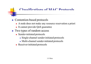
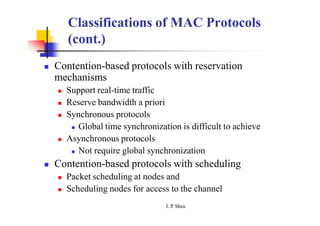
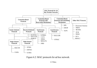
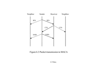
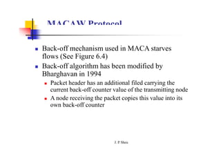
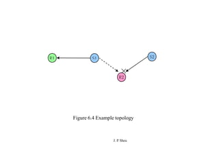
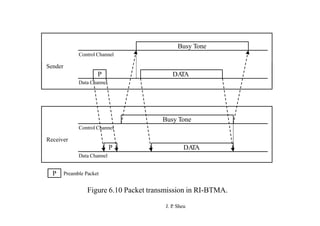
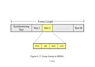
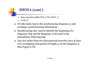
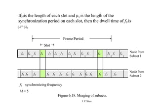
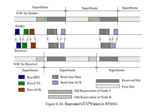
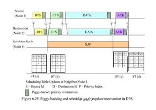
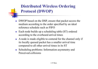
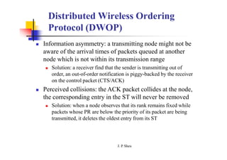
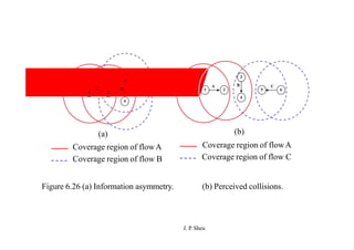
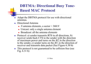
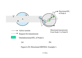
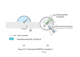
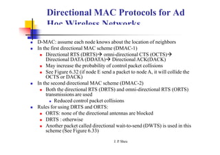
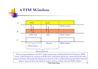
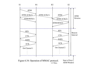
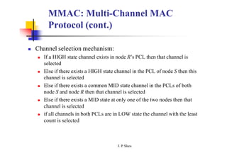
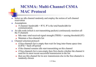
SlideShare a Scribd company logo
Chapter 6: MAC Protocols for Ad
Hoc Wireless Networks
Jang Ping Sheu
Outline
 Issues in designing a MAC protocol
 Contention-based protocols
 Contention-based protocols with reservation
mechanisms
 Contention-based protocols with scheduling
mechanisms
 Other protocols
 Summary
J. P
. Sheu
Issues in Designing a MAC Protocol
 Bandwidth Efficiency
 QoS support
 Synchronization
 Hidden and Exposed Terminal Problems
 Error-Prone Share Broadcast Channel
 Distributed Nature/Lack of Central
Coordination
 Mobility of Nodes
J. P
. Sheu
S2
R1
S1
S3
R2
Transmission range of Node S2
Packet transmission
Transmission range of Node S1
Transmission that is not permitted
Figure 6.1 Hidden and exposed terminal problems
J. P
. Sheu
Design Goals of a MAC Protocol
 Provided QoS support for real-time traffic
 Low access delay
 Bandwidth (BW) efficiently used
 Fair allocation of BW to nodes
 Low control overhead
 Scalable to large networks
 Support power control and time synchronization
 Adaptive data rate control
J. P
. Sheu
Classifications of MAC Protocols
 Contention-based protocols
 A node does not make any resource reservation a priori
 It cannot provide QoS guarantee
 Two types of random access
 Sender-initiated protocols
 Single-channel sender-initiated protocols
 Multi-channel sender-initiated protocols
 Receiver-initiated protocols
J. P
. Sheu
Classifications of MAC Protocols
(cont.)
 Contention-based protocols with reservation
mechanisms
 Support real-time traffic
 Reserve bandwidth a priori
 Synchronous protocols
 Global time synchronization is difficult to achieve
 Asynchronous protocols
 Not require global synchronization
 Contention-based protocols with scheduling
 Packet scheduling at nodes and
 Scheduling nodes for access to the channel
J. P
. Sheu
Figure 6.2: MAC protocols for ad hoc network
J. P
. Sheu
Contention-Based Protocols
MACA Protocol
 Multiple access collision avoidance protocol
proposed by Karn in 1990
 MACA does not make use of carrier-sensing
 Request-to-send (RTS), clear-to-send (CTS),
DATA messages
 Use binary exponential back-off (BEB) algorithm
for retry
 Both the RTS and CTS packets carry the
expected duration of the data packet transmission
J. P
. Sheu
MACA Protocol (cont.)
 A node near the receiver (overcome hidden node
problem)
 Hearing the CTS packet, defers its transmission
till the receiver receives the data packet
 A node near the sender (overcome exposed node
problem)
 A node that only hears the RTS is free to transmit
simultaneously when the sender is transmitting
data
J. P
. Sheu
Neighbor Sender Receiver Neighbor
RTS RTS
CTS CTS
DA
TA DA
TA
Figure 6.3 Packet transmission in MACA
J. P
. Sheu
MACAW Protocol
 Back-off mechanism used in MACA starves
flows (See Figure 6.4)
 Back-off algorithm has been modified by
Bharghavan in 1994
 Packet header has an additional filed carrying the
current back-off counter value of the transmitting node
 A node receiving the packet copies this value into its
own back-off counter
J. P
. Sheu
R1 S1 S2
×
R2
J. P
. Sheu
Figure 6.4 Example topology
MACAW Protocol (cont.)
 To prevent large variations in the back-off values
 A multiplicative increase and linear decrease
(MILD) is used in MACAW
 Collision: back-off is increased by a multiplicative
factor (1.5)
 Successful: back-off is decreased by one
 Implement per flow fairness as opposed to the per
node fairness
 Multiple queues at every node (running back-off
algorithm independently)
J. P
. Sheu
MACAW Protocol (cont.)
J. P
. Sheu
 An extra control packet ACK used in MACAW
 If ACK is not received by sender, the sender would
retry by transmitting an RTS for the same packet
 The back-off counter is incremented
 The receiver, instead sending back a CTS, sends an
ACK for the packet received
 Exposed node problem (see Figure 6.5)
 Before transmitting the data packet, the source node
transmits the data-sending (DS) packet to ensure RTS-
CTS exchange successful
R1 S1 R2
S2
Figure 6.5 Example topology
S2 R2 S1
R1
RRTS
J. P
. Sheu
RRTS
Figure 6.6 Example topology.
MACAW Protocol (cont.)
 Another control packet: request for request to
send (RRTS), See Figure 6.6
 Synchronization information needs to be propagated to
the concerned nodes
 If a node had received an RTS previously for which it
was not able to respond because there exists on-going
transmission, then it waits for the next contention
period and transmits RRTS
 Figure 6.7 shows the operation of the MACAW
protocol
 RTS-CTS-DS-DATA-ACK
J. P
. Sheu
N1 S R N2
RTS RTS
CTS CTS
DS DS
DA
TA DA
TA
ACK ACK
Figure 6.7 Packet exchange in MACAW.
J. P
. Sheu
FAMA: Floor Acquisition Multiple
Access Protocols
 Channel access consists of a carrier-sensing
operation and a collision avoidance
 Carrier-sensing by the sender, followed by the
RTS-CTS control packet exchange.
 Data transmission to be collision free, the duration of
an RTS must be at least twice the maximum channel
propagation delay
 Two FAMA protocol variants
 RTS-CTS exchange with no carrier sensing (MACA)
 RTS-CTS exchange with non-persistent carrier
sensing (FAMA-NTR)
J. P
. Sheu
FAMA-NTR
 Before sending a packet, the sender senses the channel
 If channel is busy, the sender back-off a random time and
retries later
 If the channel is free, the sender sends RTS and waits for
a CTS packet
 If the sender cannot receive a CTS, it takes a random
back-off and retries later
 If the sender receives a CTS, it can start transmission data
packet
 In order to allow the sender to send a burst of packets, the
receiver is made to wait a time duration τ seconds after a
packet is received
J. P
. Sheu
BTMA: Busy Tone Multiple Access
Protocols
 The transmission channel is split into:
 Data packet transmissions: a data channel
 Busy tone signal: a control channel
 When a node is ready for transmission, it senses the channel
to check whether the busy tone is active
 If not, it turns on busy tone signal and starts data transmission
 Otherwise, it reschedules the packet for transmission after some
random rescheduling delay.
 When a node is transmitting, no other node in the two-hop
neighborhood of the transmitting node is permitted to
simultaneously transmit (See Figure 6.8)
J. P
. Sheu
N1
Both nodes N1 and N2
transmit the busy tone.
N2
Transmission range of Node N2
Transmission range of Node N1
Region in which simultaneous transmission are not
possible when N1 is transmission data
Busy tone
J. P
. Sheu
Figure 6.8 Transmission in BTMA.
DBTMA: Dual Busy Tone Multiple
Access Protocol
 The transmission channel is divided into:
 The data channel  data packet transmission
 The control channel  RTS, CTS, busy tones
 Use two busy tones on the control channel, BTt and BTr.
 BTt : indicate that it is transmitting on the data channel
 BTr: indicate that it is receiving on the data channel
 Two busy tone signals are two sine waves at different
frequencies
J. P
. Sheu
DBTMA: Dual Busy Tone Multiple
Access Protocol (cont.)
 When a node is ready to transmit a data packet (See
Figure 6.9)
 First sense the channel to determine whether the BTr signal is active
 No BTr signal transmit RTS packet
 On receiving the RTS packets, checks whether the BTt tone is active
 No BTt signal Sending CTS packet and turn on the BTr signal
 Sender: receive CTS  turn on BTt signal  start data  turn off BTt
signal
 Receiver: receive data  turn off BTr signal
 DBTMA has better network utilization than RTS/CTS
based protocol (why?)
J. P
. Sheu
RTS CTS BTt
DATA
Data Channel
Control Channel
Sender
RTS CTS BTr
Control Channel
Receiver
DATA
Data Channel
Figure 6.9 Packet transmission in DBTMA.
J. P
. Sheu
RI-BTMA: Receiver-Initiated Busy
Tone Multiple Access Protocol
J. P
. Sheu
 The available bandwidth is divided into two
slotted channels:
 The data channel  data packet transmission
 Only if it finds the busy tone to be absent on the
control channel
 The control channel busy tone signal
 Data packet: a preamble and the actual data packet
 The busy tone serves two purposes:
 Ack the sender the successful of receiving preamble
 Inform the nearby hidden nodes the impending
transmission
RI-BTMA: Receiver-Initiated Busy
Tone Multiple Access Protocol (cont.)
 The operation of the RI-BTMA protocol (See Figure 6.10)
 Two types
 the basic protocol
 No backlog buffers  packets that suffer collisions cannot be
retransmitted
 the controlled protocol
 Backlogged mode  backlog buffer is non-empty
 Backlog buffers: transmitting a backlogged packet in the
next idle slot with a probability q (why?)
 Non-backlogged mode  transmitting a non-backlogged packet
in the next idle slot with a probability p (why?)
J. P
. Sheu
Busy Tone
DA
TA
Data Channel
Control Channel
Sender
P
Busy Tone
DA
TA
Data Channel
Control Channel
Receiver
P
P
J. P
. Sheu
Preamble Packet
Figure 6.10 Packet transmission in RI-BTMA.
MACA-BI: MACA-By Invitation
 MACA-BI is a receiver-initiated MAC protocol
 Reduced the number of control packets in MACA protocol (uses three-way
handshake mechanism)
 Receiver sends ready to receive (RTR)  Sender responds by sending a
DATA packet (See Figure 6.11)
 The receiver needs to estimate the average arrival rate of packets
 Problems:
 Receiver may not have an exact knowledge about the traffic rates
 The protocol allowing the sender to declare its backlog through the RTS
control packet, if an RTR packet is not arrived within a given timeout
 Hidden terminal problem is overcome in MACA-BI
 However, the hidden terminal problem still affects the control packet
transmission
 RTR packets can collide with DATA packets (See Figure 6.12)
J. P
. Sheu
Sender Receiver Neighbor (hidden terminal
with respect to sender)
RTR RTR
Blocked from
DA
TA transmitting
Figure 6.11 Packet transmission in MACA-BI
S1 R1 A R2 S2
PTR1 PTR1 PTR2 PTR2
S1, S2 - Sender nodes
R1, R2 - Receiver nodes
A- Neighbor node
J. P
. Sheu
Figure 6.12 Hidden terminal problem in MACA-BI
MARCH: Media Access with
Reduced Handshake
 MARCH does not require any traffic prediction mechanism
 The RTS packet is used only for the first packet of the stream
 MACA: RTS  CTS  DATA  RTS  CTS.. .
 MARCH: RTS  CTS1  DATA  CTS2  DATA … (See Figure
6.13)
 The CTS packet: MAC address of the sender, receiver, and the route
identification number (RTid) (See Figure 6.14)
 The RTid is used to avoid misinterpretation of CTS packets and
initiation of false CTS-only handshake
 For example, when node Y received a CTS with RTid = route 1, it does
not respond (See Fig. 6.14)
 The throughput of MARCH is significantly high when compared to
MACA, while the control overhead is much less
J. P
. Sheu
A B C D
RTS
CTS
CTS
A B C D
RTS
CTS1 CTS1
DATA
RTS tCSMA
DATA
CTS CTS
CTS2 CTS2 tMARCH
DATA
RTS
DATA
CTS3
DATA
CTS
DATA
(a)
J. P
. Sheu
(b)
Figure 6.13 Handshake mechanism in (a) MACAand (b) MARCH
X
A B C D E
Y
Route 1:A-B-C-D
Route 2: X-C-Y
Figure 6.14 Example Topology
J. P
. Sheu
Contention-Based Protocols with
Reservation Mechanisms
D-PRMA: Distributed Packet
Reservation Multiple Access Protocol
 The channel is divided into fixed and equal sized frames
along the time axis. (See Figure 6.15)
 The RTS/BI and CTS/BI are used for slot reservation and
for overcoming the hidden terminal problem
 If a terminal wins the contention through mini-slot 1, the
extra (m – 1) mini-slots of this slot will be granted to the
terminal as the payload
 For voice node, the same slot in each subsequent frame can be
reserved until the end of its packet transmission
 In the other cases, the extra (m – 1) mini-slots are
continuously used for contention, and the winner of this
contention will be granted the reservation of the same slot
J. P
. Sheu
Frame Length
Slot 2
Slot 1 ……………….. Slot s
Mini-slot 1 Mini-slot 2 …………… Mini-slot m
CTS/BI
RTS/BI
J. P
. Sheu
Figure 6.15 Frame structure in D-PRMA
D-PRMA (cont.)
 To prioritize voice terminals over data terminals
 Voice terminals starts contenting from mini-slot 1 with probability
p = 1 while data terminals can start such content with p < 1
 Both voice and data terminals can content through the extra (m – 1)
mini-slots with probability p < 1
 Only the winner of a voice terminal can reserve the same slot in
each subsequent frame until the end of packet transmission while
the winner of a data terminal can only use one slot
 Problems:
 When a terminal wins the contention in mini-slot 1, how to prevent
other terminals in the same slot for contention ? (Use RTS/CTS)
 How to prevent a terminal from contending for a reserved slot in
each subsequent slot ? (Transmit a busy indication (BI) signal
RTS/BI (receiver) (why?) and CTS/BI (sender) in mini-slot 1)
J. P
. Sheu
CATA: Collision Avoidance Time
Allocation Protocol
J. P
. Sheu
 Support broadcast, unicast, and multicast
transmissions simultaneously
 Each frame consists of S slots and each slot is
further divided into five mini-slots
 CMS1: Slot Reservation (SR)
 CMS2: RTS
 CMS3: CTS
 CMS4: not to send (NTS)
 DMS: Data transmission
CATA (cont.)
 Each node receives data during the DMS of current slot
transmits an SR in CMS1
 Every node that transmits data during the DMS of current
slot transmits an RTS in CMS2
 CMS3 and CMS4 are used as follows:
 The sender of an intend reservation, if it senses the channel is idle
in CMS1, transmits an RTS in CMS2
 Then the receiver transmits a CTS in CMS3
 If the reservation was successful the data can transmit in current
slot and the same slot in subsequent frames
 Once the reservation was successfully, in the next slot both the
sender and receiver do not transmit anything during CMS3 and
during CMS4 the sender transmits a NTS
J. P
. Sheu
CATA (cont.)
 If a node receives an RTS for broadcast or multicast
during CMS2 or it finds the channel to be free during
CMS2, it remains idle during CMS3 and CMS4
 Otherwise it sends a NTS packet during CMS4
 A potential multicast or broadcast source node that
receives the NTS packet or detecting noise during CMS4,
understands that its reservation is failed
 If it find the channel is free in CMS4, which implies its
reservation was successful
 CATA works well with simple single-channel half-duplex
radios
J. P
. Sheu
Frame Length
Slot 1 Slot 2 . . . . . . . . . Slot S
CMS 1 CMS 2 CMS 3 CMS 4 DMS
Figure 6.16. Frame format in CATA.
J. P
. Sheu
HRMA: Hop Reservation Multiple
Access Protocol
 HRMA is a multi-channel MAC protocol, based on half-
duplex very slow frequency hopping spread spectrum (FHSS)
radios
 Each time slot is assigned a separate frequency channel (See
Figure 6.17)
 Assumptions
 L: frequency channels
2
M   (L  1) 
 
 f0: dedicated synchronized channel frequency
 The remaining L - 1 frequencies are divided into
frequency pairs denoted by
J. P
. Sheu
*
( fi , fi ), i  1, 2 , 3,...., M
Synchronizing
Slot
Slot 1 Slot 2 . . . . . . . Slot M
Frame Length
SYN HR RTS CTS
Figure 6.17. Frame format in HRMA .
J. P
. Sheu
HRMA (cont.)
 Hop reservation (HR), RTS, CTS, DATA : fi
 ACK: fi*
 All idle nodes hop to the synchronizing frequency f0 and
exchange synchronization information
 Synchronizing slot: used to identify the beginning of a
frequency hop and the frequency to be used in the
immediately following hop
 Any two nodes from two disconnected networks have at least
two overlapping time period of length µs on the frequency f0
(See Figure 6.18)
J. P
. Sheu
Ifμis the length of each slot and μs is the length of the
synchronization period on each slot, then the dwell time of f0 is
μ+ μs
Frame Period
Slot
Node from
Subnet 1
f0 f0 f1 f0 f2 f0 f3 f0 f4 f0 f5 f0 f0 f1 f0
f0 f5 f0 f0 f1 f0 f2 f0 f3 f0 f4 f0 f5 f0
Node from
Subnet 2
f0 synchronizing frequency
M = 5
Figure 6.18. Merging of subnets.
J. P
. Sheu
HRMA (cont.)
 A node ready to transmit data, it senses the HR period of
the current slot
 If the channel is idle during HR period, it transmits an RTS during
RTS period and waits for CTS during CTS period
 If the channel is busy during HR period, it backs off for a randomly
multiple slots
 Suppose the sender needs to transmits data across multiple
frames, it informs the receiver through the header of the
data packet
 The receiver node transmits an HR packet during the HR period of
the same slot in next frame to informs its neighbors
 The sender receiving the HR packet, it sends an RTS during the
RTS period and jams other RTS packets
 Both the sender and receiver remain silent during the CTS period
J. P
. Sheu
FPRP: Five-Phase Reservation
Protocol
 FPRP is a single-channel TDMA-based broadcast scheduling protocol:
 need global time synchronization
 fully distributed and scalable
 reservation process is localized; it involves only two-hop neighbors
 No hidden terminal problem
 Time is divided into frames: reservation frame (RF) and information
frame (IF) (see Figure 6.21)
 Each RF has N reservation slots (RS) and each IF has N information slots (IS)
 Each RS is composed of M reservation cycles (RCs)
 With each RC, a five-phase dialog takes place
 Corresponding to IS, each node would be in one of the following three
states: transmit (T), receive (R), and blocked (B)
J. P
. Sheu
RF IF IF IF …….. IF IF RF IF IF IF …
IS1 IS2 . . . . ISN
RS1 RS2 . . . . RSN
RC1 RC2 . . . . RCM
RR CR RC RA P/E
Five-phase reservation dialog
Figure 6.21. Frame structure in FPRP.
J. P
. Sheu
FPRP: Five-Phase Reservation
Protocol (cont.)
 Five-phase protocol:
 Reservation request: send reservation request (RR) packet to dest.
 Collision report: if a collision is detected by any node, that node
broadcasts a CR packet
 Reservation confirmation: a source node won the contention will
send a RC packet to destination node if it does not receive any CR
message in the previous phase
 Reservation acknowledgment: destination node acknowledge
reception of RC by sending back RA message to source
 Packing and elimination: use packing packet and elimination packet
 An example is shown in Figure 6.22
J. P
. Sheu
7
8
4
5
2
11
6
1
9
3
10
RC Packet
RAPacket
RR Packet
CR Packet
Figure 6.22. FPRP - Example.
J. P
. Sheu
MACA/PR: MACA with Piggy-
Backed Reservation
J. P
. Sheu
 MACA/PR is used to provide real time traffic support
 The main components: a MAC protocol (MACAW
+ non persistent CSMA), a reservation protocol, and
a QoS routing protocol
 Each node maintains a reservation table (RT) that
records all the reserved transmit and receive
slots/windows of all nodes
 Non-real time packet: wait for a free slot in the RT +
random time  RTS  CTS  DATA  ACK
MACA/PR: MACA with Piggy-
Backed Reservation (cont.)
 Real time packet:
 Transmit real time packets at certain regular intervals
(say CYCLE)
 RTSCTSDATA (carry reservation info for next
data)  ACK…DATA (carry reservation info)
 ACK
 Hear DATA and ACK: update their reservation table
 The ACK packet serves to renew the reservation, in
addition to recovering from the packet loss
 Reservation fail: fail to receive ACK packets for a certain
number of DATA packets
J. P
. Sheu
MACA/PR: MACA with Piggy-
Backed Reservation (cont.)
 For maintaining consistent information regarding free slots
 Periodic exchange of reservation tables
 Best effort and real time packet transmissions can be interleaved
at nodes
 When a new node joins: receive reservation tables from each of
its neighbors and learns about the reservations made in the
network
 QoS Routing protocol: DSDV (destination sequenced distance
vector)
 MACA/PR does not require global synchronization among
nodes
 Drawback: possibility of many fragmented free slots not being
used at all
J. P
. Sheu
NAV for Sender
Sender
CYCLE CYCLE CYCLE
Receiver
NA
V for Receiver
RTS DA
TA Reserved Slot
CTS ACK Free Slot
Figure 6.23. Packet transmisJs. i
P
o
.S
nh
e
iu
nMACA / PR.
RTMAC: Real Time Medium Access
Control Protocol
 The two components: MAC protocol and QoS routing protocol
 QoS routing: for end to end reservation + release of bandwidth
 MAC: medium access for best effort + reservation for real time
 Control packets
 Real time : ResvRTS, ResvCTS, and ResvACK, half of DIFS
 Best effort: RTS, CTS, and ACK
 The duration of each resv-slot is twice the maximum
propagation delay
 Transmit real time packets first reserves a set of resv-slots
 The set of resv-slots for a connection is called a connection-slot
 The superframe for each node may not strictly align with the
other nodes (use relative time for all reservation)
J. P
. Sheu
Superframe
NA
V for Sender
Superframe Superframe
Sender
Receiver
NA
V for Receiver
Superframe Superframe
Superframe
Real-time Data
ResvRTS
Reserved Slot
Old Reservation of NodeA
ResvCTS
ResvACK
Real-timeACK
Free Slot
Old Reservation of Node B
Figure 6.24. ReservationJ.
mP
.
eS
che
hu
anismin RTMAC.
Contention-Based MAC Protocols
with Scheduling Mechanisms
DPS: Distributed Priority Scheduling
and MAC in Ad Hoc Networks
 Provide differentiated QoS levels to different wireless
applications in ad hoc networks
 Achievable by QoS-sensitive MAC and network layer
scheduling
 Distributed scheduling problem with local information
 Basic mechanisms:
 Piggyback information
 Head-of-line (HoL) packet as the packet with the highest priority
(lowest index)
 RTS, CTS : carry current packet info
 DATA, ACK: carry next head-of-line info
J. P
. Sheu
Source
(Node 1) RTS CTS DATA ACK
Destination
(Node 2) RTS CTS DA
TA ACK
Neighbor Node
(Node 4)
NA
V
S D P
4 5 1
7 8 5
S D P
4 5 1
7 8 5
1 2 9
S D P
S D P
4 5 1
4 5 1
7 8 5 7 8 5
1 2 9 1 6 14
1 6 14
ST (a) ST (d)
ST (c)
ST (b)
Scheduling Table Updates at Neighbor Node 4
S – Source Id D – Destination Id P – Priority Index
Piggy-backed priority information
Figure 6.25. Piggy-backing and scheduliJn.P
g.Sthaebu
leupdate mechanism in DPS.
Distributed Wireless Ordering
Protocol (DWOP)
 DWOP based on the DSP, ensure that packet access the
medium according to the order specified by an ideal
reference schedule such as FIFO
 Each node builds up a scheduling table (ST) ordered
according to the overheard arrival times
 A node is made eligible to contend for the channel only if
its locally queued packet has a smaller arrival time
compared to all other arrival times in its ST
 Scheduling problems: Information asymmetry and
Perceived collisions
J. P
. Sheu
Distributed Wireless Ordering
Protocol (DWOP)
 Information asymmetry: a transmitting node might not be
aware of the arrival times of packets queued at another
node which is not within its transmission range
 Solution: a receiver find that the sender is transmitting out of
order, an out-of-order notification is piggy-backed by the receiver
on the control packet (CTS/ACK)
 Perceived collisions: the ACK packet collides at the node,
the corresponding entry in the ST will never be removed
 Solution: when a node observes that its rank remains fixed while
packets whose PR are below the priority of its packet are being
transmitted, it deletes the oldest entry from its ST
J. P
. Sheu
2
1
3
B
A 2
1
3
B
A
6
5
C
4
4
(a)
Coverage region of flowA
Coverage region of flow B
(b)
Coverage region of flowA
Coverage region of flow C
Figure 6.26 (a) Information asymmetry.
J. P
. Sheu
(b) Perceived collisions.
MAC Protocols with Directional
Antennas
MAC Protocol Using Directional
Antennas
 Advantages
 Reduced signal interference, increase system throughput, and
improved channel reuse
 Assumptions
 Only one radio transceiver can transmit and receive only one
packet at any given time
 M directional antennas, each antennas having a conical
radiation pattern, spanning an angle of 2/M radians (See
Figure 6.28)
 Adjacent antennas never overlap
 If a node transmits when all its antennas are active, then the
transmission’s radiation pattern is similar to that of an omni-
directional antennas
 Packet transmission--See Figure 6.29
J. P
. Sheu
Radiation Pattern
forAntenna 5
Radiation Pattern
forAntenna 4
Radiation Pattern
forAntenna 6
Radiation Pattern
forAntenna 3
Radiation Pattern
forAntenna 1
Radiation Pattern
forAntenna 2
Node with 6 antennas (M = 6)
Figure 6.28. Radiation patterns of directional antennas.
J. P
. Sheu
RTS
RTS
RTS
Source Node
RTS
RTS
CTS
CTS
DATA
RTS Destination Node
CTS
CTS CTS
CTS
Figure 6.29. Packet transmission.
J. P
. Sheu
DBTMA: Directional Busy Tone-
Based MAC Protocol
 Adapt the DBTMA protocol for use with directional
antennas.
 Directional Antenna
 N antenna elements, a sector = 360/N
 Unicast: only a single antenna element
 Broadcast: all the antenna elements
 Protocol: a) sender transmits RTS in all directions, b)
receiver sends back CTS to the sender with the direction
of maximum power and turns on the BTr in the direction
to the sender, c) sender turns on the BTt in the direction of
receiver and transmits data packet (See Figure 6.30 b)
 This protocol is not guaranteed to be collision free (see
Fig. 6.31 b)
J. P
. Sheu
B
Directional BTt
of NodeA
C
A
D
C
A
B
D
Directional transmission
From Node C to Node D
Active session
Request for transmission
Omnidirectional BTt of NodeA
(a) (b)
J. P
. Sheu
Figure 6.30. Directional DBTMA: Example 1.
Directional BTr
A
A
of Node B
B
C
B
Directional transmission
From Node C to Node D
C X
D
D
Active session
Omnidirectional BTr of Node B
(a) (b)
Figure 6.31. Directional DBTMA: Example 2.
J. P
. Sheu
Directional MAC Protocols for Ad
Hoc Wireless Networks
 D-MAC: assume each node knows about the location of neighbors
 In the first directional MAC scheme (DMAC-1)
 Directional RTS (DRTS) omni-directional CTS (OCTS)
Directional DATA (DDATA) Directional ACK(DACK)
 May increase the probability of control packet collisions
 See Figure 6.32 (if node E send a packet to node A, it will collide the
OCTS or DACK)
 In the second directional MAC scheme (DMAC-2)
 Both the directional RTS (DRTS) and omni-directional RTS (ORTS)
transmissions are used
 Reduced control packet collisions
 Rules for using DRTS and ORTS:
 ORTS: none of the directional antennas are blocked
 DRTS : otherwise
 Another packet called directional wait-to-send (DWTS) is used in this
scheme (See Figure 6.33)
J. P
. Sheu
DRTS DRTS
E
DA
TA DA
TA
OCTS OCTS OCTS
A B C D
ACK ACK
Transmission Range of the Node
Control/Data Packet
Data session
Non-permissible session
Figure 6.32. Operation of DMAC protocol.
J. P
. Sheu
A B C D
DRTS
OCTS
DA
TA
OCTS ORTS
DWTS
ACK
Transmission Range of the Node
Control/Data Packet
Data session
Non-Permissible Session
Figure 6.33. Operation of DMAC protocol.
J. P
. Sheu
Other MAC Protocols
MMAC: Multi-Channel MAC
Protocol
 Assumptions:
 No dedicated control channel
 N channels for data transmission
 Each node maintains a data structure called PreferableChannelList (PCL)
 Three types for channels:
 High preference channel (HIGH): the channel is selected by the current
node and is used by the node
 Medium preference channel (MID): a channel which is free and is not
being currently used
 Low preference channel (LOW): such a channel is already being used in
the transmission range of the node by other neighboring nodes
J. P
. Sheu
MMAC: Multi-Channel MAC
Protocol (cont.)
 Time is divided into beacon intervals and every node is
synchronized by periodic beacon transmissions
 Ad hoc traffic indication messages (ATIM) window is
used to negotiate for channels for transmission
 ATIM, ATIM-ACK, and ATIM-RES (ATIM-reservation)
message
 ATIM messages takes place on a particular channel (default
channel)
 Operation of the MMAC protocol is illustrated in Figure
6.34
 The receiver plays a dominant role in channel selection
J. P
. Sheu
ATIM Window
A ATIM DATA
A
TIM window
B
C
ATIM-ACK ACK A
TIM window
A
TIM window
Dozing
ATIM window
Beacon interval
Power saving mechanism for DCF: NodeAannounces a buffered frame for B using anA
TIM
frame. Node B replies by sending anA
TIM-ACK, and bothAand B stay awake during the entire
beacon interval. The actual data transmission fromAto B is completed during the beacon interval.
Since C does not have any frame to send or receive, it dozes after theATIM window.
Chih-Yung Chang 77
S1 R1 S2
R2
A
TIM
ATIM-ACK(1) A
TIM
ATIM
Window
ATIM-ACK(1)
ATIM-RES(1) ATIM-ACK(2)
ATIM-RES(2)
RTS RTS
CTS
DA
TA
CTS
DA
TA
Beacon
Interval
ACK
On Channel 1
.
ACK
On Channel 2
.
.
.
.
.
.
.
Start of Next
A
TIM Window
Figure 6.34. Operation of MMAC protocol.
J. P
. Sheu
MMAC: Multi-Channel MAC
Protocol (cont.)
 Channel selection mechanism:
 If a HIGH state channel exists in node R’s PCL then that channel is
selected
 Else if there exists a HIGH state channel in the PCL of node S then this
channel is selected
 Else if there exists a common MID state channel in the PCLs of both
node S and node R then that channel is selected
 Else if there exists a MID state at only one of the two nodes then that
channel is selected
 if all channels in both PCLs are in LOW state the channel with the least
count is selected
J. P
. Sheu
MCSMA: Multi-Channel CSMA
MAC Protocol
 Select an idle channel randomly and employ the notion of soft channel
reservation
 Assumptions
 N channel: bandwidth = W/N, W is the total bandwidth for
communication
 An idle node (which is not transmitting packets) continuously monitors all
the N channels
 Idle state: total received signal strength (TRSS) < sensing threshold (ST)
 Maintain a free-channels list
 Channel selection protocol:
 if free-channels list is empty then wait for long inter-frame space time
(LIFS) + back-off period
 if the channel remains idle start transmitting on this channel
 if free-channels list is non-empty then first checks whether the channel it
used for its most recent successful transmission in the list
 then use this channel for its new transmission else in the free-channels is
randomly chosen
J. P
. Sheu
MCSMA: Multi-Channel CSMA
MAC Protocol (cont.)
 Before the actual packet transmission
 if TRSS of the chosen channel < ST for at least LIFS period initiate
packet transmission
 otherwise initiate back-off delay after the LIFS time period
 During the back-off period, if (TRSS of the chosen channel > ST)
back-off is immediately canceled
 A new back- off delay is scheduled when the TRSS again goes below
ST
 After successfully transmitting a packet, the sender node
notes the ID of the channel used and this channel would be
given preference for its next transmission
 When the number of channel is sufficiently large, each node
tends to reserve a channel for itself
J. P
. Sheu
PCM: Power Control MAC
Protocol for Ad Hoc Networks
J. P
. Sheu
 The PCM allows nodes to vary their transmission power levels on a
per-packet basis
 BASIC scheme
 RTS and CTS are transmitted with maximum power pmax
 The RTS is received at the receiver with signal level pr
 the receiver calculate the desired power level pdesired based on
the received power level pr, the transmitted power level pmax,
and the noise level at receiver
 In the second method, when the source receives the CTS (in
maximum power) packet, it calculates pdesired as follows:
pdesired = ( pmax/ pr) x Rxthresh x c, where Rxthresh is the minimum
necessary received signal strength and c is the constant
 Drawbacks: May the probability of collision (see Figure 6.35)
Carrier-Sensing Zone
RTS
X
For RTS
Carrier-Sensing Zone
For CTS
B
CTS
A
DA
TA
ACK
Transmission Range
for RTS
Transmission
Range for DATA
Transmission Range
for CTS
Transmission Range
forACK
Y
Figure 6.35. Packet transmissioJn. P
.inShBeuASICscheme.
PCM: Power Control MAC
Protocol for Ad Hoc Networks
 Solution:
 RTS and CTS are transmitted with maximum power pmax
 Carrier-sensing zone: the received signal is not high
enough to decode it correctly
 Transmit the DATA packet at maximum power level pmax
periodically
 The duration of each such transmission must larger
than the time required for physical carrier sensing (see
Figure 6.36)
J. P
. Sheu
EIFS
Pmax
Pdesired
0
RTS CTS DATA AC
K
SIFS
Figure 6.36 . Transmission power pattern in PCM.
J. P
. Sheu
RBAR: Receiver-Based Autorate
Protocol
 Rate Adaptation Mechanism
 run at the receiver instead of being located at the sender
 consist of channel quality estimation and rate selection
 Rate selection is done during RTS-CTS packet exchange
 The RTS and CTS packets carry the chosen modulation rate
and the size of the data packet, instead of the duration of the
reservation (see Figure 6.37)
 The rate chosen by the sender and receiver are different
 DRTS calculated by the neighbor nodes of the sender would not be valid
if the rates chosen by the sender and receiver are different
 Overcome problem: a special MAC header containing a reservation
subheader (RSH) which contains control information for determining
the transmission duration
J. P
. Sheu
RSH
RTS
J. P
. Sheu
RBAR: Receiver-Based Auto-rate
Protocol (cont.)
 Channel quality estimation
 The receiver uses a sample of the instantaneous received signal
strength at the end of RTS reception
 Rate selection algorithm
 A simple threshold based technique is used e.g. signal to noise
ratio (SNR)
 It is important that the best available channel quality
estimates are used for rate selection
J. P
. Sheu
ICSMA: Interleaved Carrier-Sense
Multiple Access Protocol
 Efficiently overcomes the exposed terminal problem (see Figure 6.38)
 Node C is called a send-exposed node, and node E is called a
receiver-exposed node
 The total available bandwidth is split into two equal channels (say,
channel 1 and channel 2)
 The handshaking process is interleaved between the two channels
 Sender uses a channel (channel 1 ) to send RTS and DATA while
receiver uses another channel (channel 2) to send CTS and ACK
 A node hear RTS in a particular channel and do not hear CTS on the
other channel, it can send RTS in the same channel
 A node hear CTS in a particular channel and do not hear RTS on the
other channel, it can send CTS in the same channel
J. P
. Sheu
A B
C E
F
D
Data session
Non-permissible session
J. P
. Sheu
ICSMA: Interleaved Carrier-Sense
Multiple Access Protocol (cont.)
 Each node maintains a structure called extended network allocation
vector (E-NAV)
 Two linked lists of blocks (SEList and REList):
 List looks like s1, f1; s2, f2;. . .; sk, fk, where si denotes start time of
the i-th block list and fi denotes finish time of the i-th block
 SEList : the node would be sender-exposed in the future such that
sj < t < fj
 REList : the node would be receiver-exposed in the future such
that sj < t < fj
 Both lists are updated when RTS and CTS packets are received
by the node
 See Figure 6.39
J. P
. Sheu
RTS DATA
Sender
CTS ACK
Receiver
Figure 6.39. (a) Packet transmissions in 802.11 DCF
J. P
. Sheu
J. P
. Sheu
Summary
 We have discussed the characteristics and operating
principles of several MAC schemes
 Several International standards exists for MANETs, such
as IEEE 802.11a, b, and g
 New Standards are still be developed such as UWB, IEEE
802.16 (WiMax)
 Future directions and current research:
 Hidden/exposed terminal problem
 Interference limited model
 Energy conservation
 Single channel v.s. Multiple channels
J. P
. Sheu
Summary (cont.)
 Multi-hop networks
 Fairness among competing nodes
 Directional antennas
 QoS issues
J. P
. Sheu
Exercises
 1, 4, 5, 10, 14, 15
J. P
. Sheu

More Related Content

Similar to wn_Chapter_6_MAC.pptx

Distributed Video Streaming over Internet
Distributed Video Streaming over InternetDistributed Video Streaming over Internet
Distributed Video Streaming over Internet
Videoguy
 
Computer network (1)
Computer network (1)Computer network (1)
Computer network (1)
NYversity
 
L2 MAC LTE PROCEDURES revC
L2 MAC LTE PROCEDURES revCL2 MAC LTE PROCEDURES revC
L2 MAC LTE PROCEDURES revC
Vincent Daumont
 
Assignment cn tl
Assignment cn tlAssignment cn tl
Assignment cn tl
H K
 
Unit III IPV6 UDP
Unit III IPV6 UDPUnit III IPV6 UDP
Unit III IPV6 UDP
sangusajjan
 

Similar to wn_Chapter_6_MAC.pptx (20)

Distributed Video Streaming over Internet
Distributed Video Streaming over InternetDistributed Video Streaming over Internet
Distributed Video Streaming over Internet
 
Ch3 transport layer Network
Ch3 transport layer NetworkCh3 transport layer Network
Ch3 transport layer Network
 
serial-200505101453.pdf
serial-200505101453.pdfserial-200505101453.pdf
serial-200505101453.pdf
 
Serial Communication
Serial CommunicationSerial Communication
Serial Communication
 
KandR_TCP (1).ppt notes for congestion control
KandR_TCP (1).ppt    notes for congestion controlKandR_TCP (1).ppt    notes for congestion control
KandR_TCP (1).ppt notes for congestion control
 
Computer Networks Module 2.pdf
Computer Networks Module 2.pdfComputer Networks Module 2.pdf
Computer Networks Module 2.pdf
 
Computer network (1)
Computer network (1)Computer network (1)
Computer network (1)
 
Transport layer
Transport layerTransport layer
Transport layer
 
Unit 2 data link control
Unit 2 data link controlUnit 2 data link control
Unit 2 data link control
 
Research Inventy : International Journal of Engineering and Science
Research Inventy : International Journal of Engineering and ScienceResearch Inventy : International Journal of Engineering and Science
Research Inventy : International Journal of Engineering and Science
 
Mcseminar
McseminarMcseminar
Mcseminar
 
L2 MAC LTE PROCEDURES revC
L2 MAC LTE PROCEDURES revCL2 MAC LTE PROCEDURES revC
L2 MAC LTE PROCEDURES revC
 
An Implementation and Analysis of RTS/CTS Mechanism for Data Transfer in Wire...
An Implementation and Analysis of RTS/CTS Mechanism for Data Transfer in Wire...An Implementation and Analysis of RTS/CTS Mechanism for Data Transfer in Wire...
An Implementation and Analysis of RTS/CTS Mechanism for Data Transfer in Wire...
 
B010611015
B010611015B010611015
B010611015
 
6 data linkcontrol
6  data linkcontrol6  data linkcontrol
6 data linkcontrol
 
Week8 lec1-bscs1
Week8 lec1-bscs1Week8 lec1-bscs1
Week8 lec1-bscs1
 
csma ca
 csma ca csma ca
csma ca
 
Assignment cn tl
Assignment cn tlAssignment cn tl
Assignment cn tl
 
Unit III IPV6 UDP
Unit III IPV6 UDPUnit III IPV6 UDP
Unit III IPV6 UDP
 
Chapter 11: Data Link Control
Chapter 11: Data Link ControlChapter 11: Data Link Control
Chapter 11: Data Link Control
 

Recently uploaded

Hall booking system project report .pdf
Hall booking system project report  .pdfHall booking system project report  .pdf
Hall booking system project report .pdf
Kamal Acharya
 
Digital Signal Processing Lecture notes n.pdf
Digital Signal Processing Lecture notes n.pdfDigital Signal Processing Lecture notes n.pdf
Digital Signal Processing Lecture notes n.pdf
AbrahamGadissa
 
Fruit shop management system project report.pdf
Fruit shop management system project report.pdfFruit shop management system project report.pdf
Fruit shop management system project report.pdf
Kamal Acharya
 
Automobile Management System Project Report.pdf
Automobile Management System Project Report.pdfAutomobile Management System Project Report.pdf
Automobile Management System Project Report.pdf
Kamal Acharya
 
power quality voltage fluctuation UNIT - I.pptx
power quality voltage fluctuation UNIT - I.pptxpower quality voltage fluctuation UNIT - I.pptx
power quality voltage fluctuation UNIT - I.pptx
ViniHema
 
CFD Simulation of By-pass Flow in a HRSG module by R&R Consult.pptx
CFD Simulation of By-pass Flow in a HRSG module by R&R Consult.pptxCFD Simulation of By-pass Flow in a HRSG module by R&R Consult.pptx
CFD Simulation of By-pass Flow in a HRSG module by R&R Consult.pptx
R&R Consult
 
RS Khurmi Machine Design Clutch and Brake Exercise Numerical Solutions
RS Khurmi Machine Design Clutch and Brake Exercise Numerical SolutionsRS Khurmi Machine Design Clutch and Brake Exercise Numerical Solutions
RS Khurmi Machine Design Clutch and Brake Exercise Numerical Solutions
Atif Razi
 
Standard Reomte Control Interface - Neometrix
Standard Reomte Control Interface - NeometrixStandard Reomte Control Interface - Neometrix
Standard Reomte Control Interface - Neometrix
Neometrix_Engineering_Pvt_Ltd
 

Recently uploaded (20)

Quality defects in TMT Bars, Possible causes and Potential Solutions.
Quality defects in TMT Bars, Possible causes and Potential Solutions.Quality defects in TMT Bars, Possible causes and Potential Solutions.
Quality defects in TMT Bars, Possible causes and Potential Solutions.
 
Hall booking system project report .pdf
Hall booking system project report  .pdfHall booking system project report  .pdf
Hall booking system project report .pdf
 
Event Management System Vb Net Project Report.pdf
Event Management System Vb Net  Project Report.pdfEvent Management System Vb Net  Project Report.pdf
Event Management System Vb Net Project Report.pdf
 
Student information management system project report ii.pdf
Student information management system project report ii.pdfStudent information management system project report ii.pdf
Student information management system project report ii.pdf
 
Digital Signal Processing Lecture notes n.pdf
Digital Signal Processing Lecture notes n.pdfDigital Signal Processing Lecture notes n.pdf
Digital Signal Processing Lecture notes n.pdf
 
Fruit shop management system project report.pdf
Fruit shop management system project report.pdfFruit shop management system project report.pdf
Fruit shop management system project report.pdf
 
Automobile Management System Project Report.pdf
Automobile Management System Project Report.pdfAutomobile Management System Project Report.pdf
Automobile Management System Project Report.pdf
 
weather web application report.pdf
weather web application report.pdfweather web application report.pdf
weather web application report.pdf
 
power quality voltage fluctuation UNIT - I.pptx
power quality voltage fluctuation UNIT - I.pptxpower quality voltage fluctuation UNIT - I.pptx
power quality voltage fluctuation UNIT - I.pptx
 
Introduction to Casting Processes in Manufacturing
Introduction to Casting Processes in ManufacturingIntroduction to Casting Processes in Manufacturing
Introduction to Casting Processes in Manufacturing
 
Sachpazis:Terzaghi Bearing Capacity Estimation in simple terms with Calculati...
Sachpazis:Terzaghi Bearing Capacity Estimation in simple terms with Calculati...Sachpazis:Terzaghi Bearing Capacity Estimation in simple terms with Calculati...
Sachpazis:Terzaghi Bearing Capacity Estimation in simple terms with Calculati...
 
The Benefits and Techniques of Trenchless Pipe Repair.pdf
The Benefits and Techniques of Trenchless Pipe Repair.pdfThe Benefits and Techniques of Trenchless Pipe Repair.pdf
The Benefits and Techniques of Trenchless Pipe Repair.pdf
 
Vaccine management system project report documentation..pdf
Vaccine management system project report documentation..pdfVaccine management system project report documentation..pdf
Vaccine management system project report documentation..pdf
 
CFD Simulation of By-pass Flow in a HRSG module by R&R Consult.pptx
CFD Simulation of By-pass Flow in a HRSG module by R&R Consult.pptxCFD Simulation of By-pass Flow in a HRSG module by R&R Consult.pptx
CFD Simulation of By-pass Flow in a HRSG module by R&R Consult.pptx
 
RS Khurmi Machine Design Clutch and Brake Exercise Numerical Solutions
RS Khurmi Machine Design Clutch and Brake Exercise Numerical SolutionsRS Khurmi Machine Design Clutch and Brake Exercise Numerical Solutions
RS Khurmi Machine Design Clutch and Brake Exercise Numerical Solutions
 
Cloud-Computing_CSE311_Computer-Networking CSE GUB BD - Shahidul.pptx
Cloud-Computing_CSE311_Computer-Networking CSE GUB BD - Shahidul.pptxCloud-Computing_CSE311_Computer-Networking CSE GUB BD - Shahidul.pptx
Cloud-Computing_CSE311_Computer-Networking CSE GUB BD - Shahidul.pptx
 
A case study of cinema management system project report..pdf
A case study of cinema management system project report..pdfA case study of cinema management system project report..pdf
A case study of cinema management system project report..pdf
 
Standard Reomte Control Interface - Neometrix
Standard Reomte Control Interface - NeometrixStandard Reomte Control Interface - Neometrix
Standard Reomte Control Interface - Neometrix
 
HYDROPOWER - Hydroelectric power generation
HYDROPOWER - Hydroelectric power generationHYDROPOWER - Hydroelectric power generation
HYDROPOWER - Hydroelectric power generation
 
Halogenation process of chemical process industries
Halogenation process of chemical process industriesHalogenation process of chemical process industries
Halogenation process of chemical process industries
 

wn_Chapter_6_MAC.pptx

  • 1. Chapter 6: MAC Protocols for Ad Hoc Wireless Networks Jang Ping Sheu
  • 2. Outline  Issues in designing a MAC protocol  Contention-based protocols  Contention-based protocols with reservation mechanisms  Contention-based protocols with scheduling mechanisms  Other protocols  Summary J. P . Sheu
  • 3. Issues in Designing a MAC Protocol  Bandwidth Efficiency  QoS support  Synchronization  Hidden and Exposed Terminal Problems  Error-Prone Share Broadcast Channel  Distributed Nature/Lack of Central Coordination  Mobility of Nodes J. P . Sheu
  • 4. S2 R1 S1 S3 R2 Transmission range of Node S2 Packet transmission Transmission range of Node S1 Transmission that is not permitted Figure 6.1 Hidden and exposed terminal problems J. P . Sheu
  • 5. Design Goals of a MAC Protocol  Provided QoS support for real-time traffic  Low access delay  Bandwidth (BW) efficiently used  Fair allocation of BW to nodes  Low control overhead  Scalable to large networks  Support power control and time synchronization  Adaptive data rate control J. P . Sheu
  • 6. Classifications of MAC Protocols  Contention-based protocols  A node does not make any resource reservation a priori  It cannot provide QoS guarantee  Two types of random access  Sender-initiated protocols  Single-channel sender-initiated protocols  Multi-channel sender-initiated protocols  Receiver-initiated protocols J. P . Sheu
  • 7. Classifications of MAC Protocols (cont.)  Contention-based protocols with reservation mechanisms  Support real-time traffic  Reserve bandwidth a priori  Synchronous protocols  Global time synchronization is difficult to achieve  Asynchronous protocols  Not require global synchronization  Contention-based protocols with scheduling  Packet scheduling at nodes and  Scheduling nodes for access to the channel J. P . Sheu
  • 8. Figure 6.2: MAC protocols for ad hoc network J. P . Sheu
  • 10. MACA Protocol  Multiple access collision avoidance protocol proposed by Karn in 1990  MACA does not make use of carrier-sensing  Request-to-send (RTS), clear-to-send (CTS), DATA messages  Use binary exponential back-off (BEB) algorithm for retry  Both the RTS and CTS packets carry the expected duration of the data packet transmission J. P . Sheu
  • 11. MACA Protocol (cont.)  A node near the receiver (overcome hidden node problem)  Hearing the CTS packet, defers its transmission till the receiver receives the data packet  A node near the sender (overcome exposed node problem)  A node that only hears the RTS is free to transmit simultaneously when the sender is transmitting data J. P . Sheu
  • 12. Neighbor Sender Receiver Neighbor RTS RTS CTS CTS DA TA DA TA Figure 6.3 Packet transmission in MACA J. P . Sheu
  • 13. MACAW Protocol  Back-off mechanism used in MACA starves flows (See Figure 6.4)  Back-off algorithm has been modified by Bharghavan in 1994  Packet header has an additional filed carrying the current back-off counter value of the transmitting node  A node receiving the packet copies this value into its own back-off counter J. P . Sheu
  • 14. R1 S1 S2 × R2 J. P . Sheu Figure 6.4 Example topology
  • 15. MACAW Protocol (cont.)  To prevent large variations in the back-off values  A multiplicative increase and linear decrease (MILD) is used in MACAW  Collision: back-off is increased by a multiplicative factor (1.5)  Successful: back-off is decreased by one  Implement per flow fairness as opposed to the per node fairness  Multiple queues at every node (running back-off algorithm independently) J. P . Sheu
  • 16. MACAW Protocol (cont.) J. P . Sheu  An extra control packet ACK used in MACAW  If ACK is not received by sender, the sender would retry by transmitting an RTS for the same packet  The back-off counter is incremented  The receiver, instead sending back a CTS, sends an ACK for the packet received  Exposed node problem (see Figure 6.5)  Before transmitting the data packet, the source node transmits the data-sending (DS) packet to ensure RTS- CTS exchange successful
  • 17. R1 S1 R2 S2 Figure 6.5 Example topology S2 R2 S1 R1 RRTS J. P . Sheu RRTS Figure 6.6 Example topology.
  • 18. MACAW Protocol (cont.)  Another control packet: request for request to send (RRTS), See Figure 6.6  Synchronization information needs to be propagated to the concerned nodes  If a node had received an RTS previously for which it was not able to respond because there exists on-going transmission, then it waits for the next contention period and transmits RRTS  Figure 6.7 shows the operation of the MACAW protocol  RTS-CTS-DS-DATA-ACK J. P . Sheu
  • 19. N1 S R N2 RTS RTS CTS CTS DS DS DA TA DA TA ACK ACK Figure 6.7 Packet exchange in MACAW. J. P . Sheu
  • 20. FAMA: Floor Acquisition Multiple Access Protocols  Channel access consists of a carrier-sensing operation and a collision avoidance  Carrier-sensing by the sender, followed by the RTS-CTS control packet exchange.  Data transmission to be collision free, the duration of an RTS must be at least twice the maximum channel propagation delay  Two FAMA protocol variants  RTS-CTS exchange with no carrier sensing (MACA)  RTS-CTS exchange with non-persistent carrier sensing (FAMA-NTR) J. P . Sheu
  • 21. FAMA-NTR  Before sending a packet, the sender senses the channel  If channel is busy, the sender back-off a random time and retries later  If the channel is free, the sender sends RTS and waits for a CTS packet  If the sender cannot receive a CTS, it takes a random back-off and retries later  If the sender receives a CTS, it can start transmission data packet  In order to allow the sender to send a burst of packets, the receiver is made to wait a time duration τ seconds after a packet is received J. P . Sheu
  • 22. BTMA: Busy Tone Multiple Access Protocols  The transmission channel is split into:  Data packet transmissions: a data channel  Busy tone signal: a control channel  When a node is ready for transmission, it senses the channel to check whether the busy tone is active  If not, it turns on busy tone signal and starts data transmission  Otherwise, it reschedules the packet for transmission after some random rescheduling delay.  When a node is transmitting, no other node in the two-hop neighborhood of the transmitting node is permitted to simultaneously transmit (See Figure 6.8) J. P . Sheu
  • 23. N1 Both nodes N1 and N2 transmit the busy tone. N2 Transmission range of Node N2 Transmission range of Node N1 Region in which simultaneous transmission are not possible when N1 is transmission data Busy tone J. P . Sheu Figure 6.8 Transmission in BTMA.
  • 24. DBTMA: Dual Busy Tone Multiple Access Protocol  The transmission channel is divided into:  The data channel  data packet transmission  The control channel  RTS, CTS, busy tones  Use two busy tones on the control channel, BTt and BTr.  BTt : indicate that it is transmitting on the data channel  BTr: indicate that it is receiving on the data channel  Two busy tone signals are two sine waves at different frequencies J. P . Sheu
  • 25. DBTMA: Dual Busy Tone Multiple Access Protocol (cont.)  When a node is ready to transmit a data packet (See Figure 6.9)  First sense the channel to determine whether the BTr signal is active  No BTr signal transmit RTS packet  On receiving the RTS packets, checks whether the BTt tone is active  No BTt signal Sending CTS packet and turn on the BTr signal  Sender: receive CTS  turn on BTt signal  start data  turn off BTt signal  Receiver: receive data  turn off BTr signal  DBTMA has better network utilization than RTS/CTS based protocol (why?) J. P . Sheu
  • 26. RTS CTS BTt DATA Data Channel Control Channel Sender RTS CTS BTr Control Channel Receiver DATA Data Channel Figure 6.9 Packet transmission in DBTMA. J. P . Sheu
  • 27. RI-BTMA: Receiver-Initiated Busy Tone Multiple Access Protocol J. P . Sheu  The available bandwidth is divided into two slotted channels:  The data channel  data packet transmission  Only if it finds the busy tone to be absent on the control channel  The control channel busy tone signal  Data packet: a preamble and the actual data packet  The busy tone serves two purposes:  Ack the sender the successful of receiving preamble  Inform the nearby hidden nodes the impending transmission
  • 28. RI-BTMA: Receiver-Initiated Busy Tone Multiple Access Protocol (cont.)  The operation of the RI-BTMA protocol (See Figure 6.10)  Two types  the basic protocol  No backlog buffers  packets that suffer collisions cannot be retransmitted  the controlled protocol  Backlogged mode  backlog buffer is non-empty  Backlog buffers: transmitting a backlogged packet in the next idle slot with a probability q (why?)  Non-backlogged mode  transmitting a non-backlogged packet in the next idle slot with a probability p (why?) J. P . Sheu
  • 29. Busy Tone DA TA Data Channel Control Channel Sender P Busy Tone DA TA Data Channel Control Channel Receiver P P J. P . Sheu Preamble Packet Figure 6.10 Packet transmission in RI-BTMA.
  • 30. MACA-BI: MACA-By Invitation  MACA-BI is a receiver-initiated MAC protocol  Reduced the number of control packets in MACA protocol (uses three-way handshake mechanism)  Receiver sends ready to receive (RTR)  Sender responds by sending a DATA packet (See Figure 6.11)  The receiver needs to estimate the average arrival rate of packets  Problems:  Receiver may not have an exact knowledge about the traffic rates  The protocol allowing the sender to declare its backlog through the RTS control packet, if an RTR packet is not arrived within a given timeout  Hidden terminal problem is overcome in MACA-BI  However, the hidden terminal problem still affects the control packet transmission  RTR packets can collide with DATA packets (See Figure 6.12) J. P . Sheu
  • 31. Sender Receiver Neighbor (hidden terminal with respect to sender) RTR RTR Blocked from DA TA transmitting Figure 6.11 Packet transmission in MACA-BI S1 R1 A R2 S2 PTR1 PTR1 PTR2 PTR2 S1, S2 - Sender nodes R1, R2 - Receiver nodes A- Neighbor node J. P . Sheu Figure 6.12 Hidden terminal problem in MACA-BI
  • 32. MARCH: Media Access with Reduced Handshake  MARCH does not require any traffic prediction mechanism  The RTS packet is used only for the first packet of the stream  MACA: RTS  CTS  DATA  RTS  CTS.. .  MARCH: RTS  CTS1  DATA  CTS2  DATA … (See Figure 6.13)  The CTS packet: MAC address of the sender, receiver, and the route identification number (RTid) (See Figure 6.14)  The RTid is used to avoid misinterpretation of CTS packets and initiation of false CTS-only handshake  For example, when node Y received a CTS with RTid = route 1, it does not respond (See Fig. 6.14)  The throughput of MARCH is significantly high when compared to MACA, while the control overhead is much less J. P . Sheu
  • 33. A B C D RTS CTS CTS A B C D RTS CTS1 CTS1 DATA RTS tCSMA DATA CTS CTS CTS2 CTS2 tMARCH DATA RTS DATA CTS3 DATA CTS DATA (a) J. P . Sheu (b) Figure 6.13 Handshake mechanism in (a) MACAand (b) MARCH
  • 34. X A B C D E Y Route 1:A-B-C-D Route 2: X-C-Y Figure 6.14 Example Topology J. P . Sheu
  • 36. D-PRMA: Distributed Packet Reservation Multiple Access Protocol  The channel is divided into fixed and equal sized frames along the time axis. (See Figure 6.15)  The RTS/BI and CTS/BI are used for slot reservation and for overcoming the hidden terminal problem  If a terminal wins the contention through mini-slot 1, the extra (m – 1) mini-slots of this slot will be granted to the terminal as the payload  For voice node, the same slot in each subsequent frame can be reserved until the end of its packet transmission  In the other cases, the extra (m – 1) mini-slots are continuously used for contention, and the winner of this contention will be granted the reservation of the same slot J. P . Sheu
  • 37. Frame Length Slot 2 Slot 1 ……………….. Slot s Mini-slot 1 Mini-slot 2 …………… Mini-slot m CTS/BI RTS/BI J. P . Sheu Figure 6.15 Frame structure in D-PRMA
  • 38. D-PRMA (cont.)  To prioritize voice terminals over data terminals  Voice terminals starts contenting from mini-slot 1 with probability p = 1 while data terminals can start such content with p < 1  Both voice and data terminals can content through the extra (m – 1) mini-slots with probability p < 1  Only the winner of a voice terminal can reserve the same slot in each subsequent frame until the end of packet transmission while the winner of a data terminal can only use one slot  Problems:  When a terminal wins the contention in mini-slot 1, how to prevent other terminals in the same slot for contention ? (Use RTS/CTS)  How to prevent a terminal from contending for a reserved slot in each subsequent slot ? (Transmit a busy indication (BI) signal RTS/BI (receiver) (why?) and CTS/BI (sender) in mini-slot 1) J. P . Sheu
  • 39. CATA: Collision Avoidance Time Allocation Protocol J. P . Sheu  Support broadcast, unicast, and multicast transmissions simultaneously  Each frame consists of S slots and each slot is further divided into five mini-slots  CMS1: Slot Reservation (SR)  CMS2: RTS  CMS3: CTS  CMS4: not to send (NTS)  DMS: Data transmission
  • 40. CATA (cont.)  Each node receives data during the DMS of current slot transmits an SR in CMS1  Every node that transmits data during the DMS of current slot transmits an RTS in CMS2  CMS3 and CMS4 are used as follows:  The sender of an intend reservation, if it senses the channel is idle in CMS1, transmits an RTS in CMS2  Then the receiver transmits a CTS in CMS3  If the reservation was successful the data can transmit in current slot and the same slot in subsequent frames  Once the reservation was successfully, in the next slot both the sender and receiver do not transmit anything during CMS3 and during CMS4 the sender transmits a NTS J. P . Sheu
  • 41. CATA (cont.)  If a node receives an RTS for broadcast or multicast during CMS2 or it finds the channel to be free during CMS2, it remains idle during CMS3 and CMS4  Otherwise it sends a NTS packet during CMS4  A potential multicast or broadcast source node that receives the NTS packet or detecting noise during CMS4, understands that its reservation is failed  If it find the channel is free in CMS4, which implies its reservation was successful  CATA works well with simple single-channel half-duplex radios J. P . Sheu
  • 42. Frame Length Slot 1 Slot 2 . . . . . . . . . Slot S CMS 1 CMS 2 CMS 3 CMS 4 DMS Figure 6.16. Frame format in CATA. J. P . Sheu
  • 43. HRMA: Hop Reservation Multiple Access Protocol  HRMA is a multi-channel MAC protocol, based on half- duplex very slow frequency hopping spread spectrum (FHSS) radios  Each time slot is assigned a separate frequency channel (See Figure 6.17)  Assumptions  L: frequency channels 2 M   (L  1)     f0: dedicated synchronized channel frequency  The remaining L - 1 frequencies are divided into frequency pairs denoted by J. P . Sheu * ( fi , fi ), i  1, 2 , 3,...., M
  • 44. Synchronizing Slot Slot 1 Slot 2 . . . . . . . Slot M Frame Length SYN HR RTS CTS Figure 6.17. Frame format in HRMA . J. P . Sheu
  • 45. HRMA (cont.)  Hop reservation (HR), RTS, CTS, DATA : fi  ACK: fi*  All idle nodes hop to the synchronizing frequency f0 and exchange synchronization information  Synchronizing slot: used to identify the beginning of a frequency hop and the frequency to be used in the immediately following hop  Any two nodes from two disconnected networks have at least two overlapping time period of length µs on the frequency f0 (See Figure 6.18) J. P . Sheu
  • 46. Ifμis the length of each slot and μs is the length of the synchronization period on each slot, then the dwell time of f0 is μ+ μs Frame Period Slot Node from Subnet 1 f0 f0 f1 f0 f2 f0 f3 f0 f4 f0 f5 f0 f0 f1 f0 f0 f5 f0 f0 f1 f0 f2 f0 f3 f0 f4 f0 f5 f0 Node from Subnet 2 f0 synchronizing frequency M = 5 Figure 6.18. Merging of subnets. J. P . Sheu
  • 47. HRMA (cont.)  A node ready to transmit data, it senses the HR period of the current slot  If the channel is idle during HR period, it transmits an RTS during RTS period and waits for CTS during CTS period  If the channel is busy during HR period, it backs off for a randomly multiple slots  Suppose the sender needs to transmits data across multiple frames, it informs the receiver through the header of the data packet  The receiver node transmits an HR packet during the HR period of the same slot in next frame to informs its neighbors  The sender receiving the HR packet, it sends an RTS during the RTS period and jams other RTS packets  Both the sender and receiver remain silent during the CTS period J. P . Sheu
  • 48. FPRP: Five-Phase Reservation Protocol  FPRP is a single-channel TDMA-based broadcast scheduling protocol:  need global time synchronization  fully distributed and scalable  reservation process is localized; it involves only two-hop neighbors  No hidden terminal problem  Time is divided into frames: reservation frame (RF) and information frame (IF) (see Figure 6.21)  Each RF has N reservation slots (RS) and each IF has N information slots (IS)  Each RS is composed of M reservation cycles (RCs)  With each RC, a five-phase dialog takes place  Corresponding to IS, each node would be in one of the following three states: transmit (T), receive (R), and blocked (B) J. P . Sheu
  • 49. RF IF IF IF …….. IF IF RF IF IF IF … IS1 IS2 . . . . ISN RS1 RS2 . . . . RSN RC1 RC2 . . . . RCM RR CR RC RA P/E Five-phase reservation dialog Figure 6.21. Frame structure in FPRP. J. P . Sheu
  • 50. FPRP: Five-Phase Reservation Protocol (cont.)  Five-phase protocol:  Reservation request: send reservation request (RR) packet to dest.  Collision report: if a collision is detected by any node, that node broadcasts a CR packet  Reservation confirmation: a source node won the contention will send a RC packet to destination node if it does not receive any CR message in the previous phase  Reservation acknowledgment: destination node acknowledge reception of RC by sending back RA message to source  Packing and elimination: use packing packet and elimination packet  An example is shown in Figure 6.22 J. P . Sheu
  • 51. 7 8 4 5 2 11 6 1 9 3 10 RC Packet RAPacket RR Packet CR Packet Figure 6.22. FPRP - Example. J. P . Sheu
  • 52. MACA/PR: MACA with Piggy- Backed Reservation J. P . Sheu  MACA/PR is used to provide real time traffic support  The main components: a MAC protocol (MACAW + non persistent CSMA), a reservation protocol, and a QoS routing protocol  Each node maintains a reservation table (RT) that records all the reserved transmit and receive slots/windows of all nodes  Non-real time packet: wait for a free slot in the RT + random time  RTS  CTS  DATA  ACK
  • 53. MACA/PR: MACA with Piggy- Backed Reservation (cont.)  Real time packet:  Transmit real time packets at certain regular intervals (say CYCLE)  RTSCTSDATA (carry reservation info for next data)  ACK…DATA (carry reservation info)  ACK  Hear DATA and ACK: update their reservation table  The ACK packet serves to renew the reservation, in addition to recovering from the packet loss  Reservation fail: fail to receive ACK packets for a certain number of DATA packets J. P . Sheu
  • 54. MACA/PR: MACA with Piggy- Backed Reservation (cont.)  For maintaining consistent information regarding free slots  Periodic exchange of reservation tables  Best effort and real time packet transmissions can be interleaved at nodes  When a new node joins: receive reservation tables from each of its neighbors and learns about the reservations made in the network  QoS Routing protocol: DSDV (destination sequenced distance vector)  MACA/PR does not require global synchronization among nodes  Drawback: possibility of many fragmented free slots not being used at all J. P . Sheu
  • 55. NAV for Sender Sender CYCLE CYCLE CYCLE Receiver NA V for Receiver RTS DA TA Reserved Slot CTS ACK Free Slot Figure 6.23. Packet transmisJs. i P o .S nh e iu nMACA / PR.
  • 56. RTMAC: Real Time Medium Access Control Protocol  The two components: MAC protocol and QoS routing protocol  QoS routing: for end to end reservation + release of bandwidth  MAC: medium access for best effort + reservation for real time  Control packets  Real time : ResvRTS, ResvCTS, and ResvACK, half of DIFS  Best effort: RTS, CTS, and ACK  The duration of each resv-slot is twice the maximum propagation delay  Transmit real time packets first reserves a set of resv-slots  The set of resv-slots for a connection is called a connection-slot  The superframe for each node may not strictly align with the other nodes (use relative time for all reservation) J. P . Sheu
  • 57. Superframe NA V for Sender Superframe Superframe Sender Receiver NA V for Receiver Superframe Superframe Superframe Real-time Data ResvRTS Reserved Slot Old Reservation of NodeA ResvCTS ResvACK Real-timeACK Free Slot Old Reservation of Node B Figure 6.24. ReservationJ. mP . eS che hu anismin RTMAC.
  • 58. Contention-Based MAC Protocols with Scheduling Mechanisms
  • 59. DPS: Distributed Priority Scheduling and MAC in Ad Hoc Networks  Provide differentiated QoS levels to different wireless applications in ad hoc networks  Achievable by QoS-sensitive MAC and network layer scheduling  Distributed scheduling problem with local information  Basic mechanisms:  Piggyback information  Head-of-line (HoL) packet as the packet with the highest priority (lowest index)  RTS, CTS : carry current packet info  DATA, ACK: carry next head-of-line info J. P . Sheu
  • 60. Source (Node 1) RTS CTS DATA ACK Destination (Node 2) RTS CTS DA TA ACK Neighbor Node (Node 4) NA V S D P 4 5 1 7 8 5 S D P 4 5 1 7 8 5 1 2 9 S D P S D P 4 5 1 4 5 1 7 8 5 7 8 5 1 2 9 1 6 14 1 6 14 ST (a) ST (d) ST (c) ST (b) Scheduling Table Updates at Neighbor Node 4 S – Source Id D – Destination Id P – Priority Index Piggy-backed priority information Figure 6.25. Piggy-backing and scheduliJn.P g.Sthaebu leupdate mechanism in DPS.
  • 61. Distributed Wireless Ordering Protocol (DWOP)  DWOP based on the DSP, ensure that packet access the medium according to the order specified by an ideal reference schedule such as FIFO  Each node builds up a scheduling table (ST) ordered according to the overheard arrival times  A node is made eligible to contend for the channel only if its locally queued packet has a smaller arrival time compared to all other arrival times in its ST  Scheduling problems: Information asymmetry and Perceived collisions J. P . Sheu
  • 62. Distributed Wireless Ordering Protocol (DWOP)  Information asymmetry: a transmitting node might not be aware of the arrival times of packets queued at another node which is not within its transmission range  Solution: a receiver find that the sender is transmitting out of order, an out-of-order notification is piggy-backed by the receiver on the control packet (CTS/ACK)  Perceived collisions: the ACK packet collides at the node, the corresponding entry in the ST will never be removed  Solution: when a node observes that its rank remains fixed while packets whose PR are below the priority of its packet are being transmitted, it deletes the oldest entry from its ST J. P . Sheu
  • 63. 2 1 3 B A 2 1 3 B A 6 5 C 4 4 (a) Coverage region of flowA Coverage region of flow B (b) Coverage region of flowA Coverage region of flow C Figure 6.26 (a) Information asymmetry. J. P . Sheu (b) Perceived collisions.
  • 64. MAC Protocols with Directional Antennas
  • 65. MAC Protocol Using Directional Antennas  Advantages  Reduced signal interference, increase system throughput, and improved channel reuse  Assumptions  Only one radio transceiver can transmit and receive only one packet at any given time  M directional antennas, each antennas having a conical radiation pattern, spanning an angle of 2/M radians (See Figure 6.28)  Adjacent antennas never overlap  If a node transmits when all its antennas are active, then the transmission’s radiation pattern is similar to that of an omni- directional antennas  Packet transmission--See Figure 6.29 J. P . Sheu
  • 66. Radiation Pattern forAntenna 5 Radiation Pattern forAntenna 4 Radiation Pattern forAntenna 6 Radiation Pattern forAntenna 3 Radiation Pattern forAntenna 1 Radiation Pattern forAntenna 2 Node with 6 antennas (M = 6) Figure 6.28. Radiation patterns of directional antennas. J. P . Sheu
  • 67. RTS RTS RTS Source Node RTS RTS CTS CTS DATA RTS Destination Node CTS CTS CTS CTS Figure 6.29. Packet transmission. J. P . Sheu
  • 68. DBTMA: Directional Busy Tone- Based MAC Protocol  Adapt the DBTMA protocol for use with directional antennas.  Directional Antenna  N antenna elements, a sector = 360/N  Unicast: only a single antenna element  Broadcast: all the antenna elements  Protocol: a) sender transmits RTS in all directions, b) receiver sends back CTS to the sender with the direction of maximum power and turns on the BTr in the direction to the sender, c) sender turns on the BTt in the direction of receiver and transmits data packet (See Figure 6.30 b)  This protocol is not guaranteed to be collision free (see Fig. 6.31 b) J. P . Sheu
  • 69. B Directional BTt of NodeA C A D C A B D Directional transmission From Node C to Node D Active session Request for transmission Omnidirectional BTt of NodeA (a) (b) J. P . Sheu Figure 6.30. Directional DBTMA: Example 1.
  • 70. Directional BTr A A of Node B B C B Directional transmission From Node C to Node D C X D D Active session Omnidirectional BTr of Node B (a) (b) Figure 6.31. Directional DBTMA: Example 2. J. P . Sheu
  • 71. Directional MAC Protocols for Ad Hoc Wireless Networks  D-MAC: assume each node knows about the location of neighbors  In the first directional MAC scheme (DMAC-1)  Directional RTS (DRTS) omni-directional CTS (OCTS) Directional DATA (DDATA) Directional ACK(DACK)  May increase the probability of control packet collisions  See Figure 6.32 (if node E send a packet to node A, it will collide the OCTS or DACK)  In the second directional MAC scheme (DMAC-2)  Both the directional RTS (DRTS) and omni-directional RTS (ORTS) transmissions are used  Reduced control packet collisions  Rules for using DRTS and ORTS:  ORTS: none of the directional antennas are blocked  DRTS : otherwise  Another packet called directional wait-to-send (DWTS) is used in this scheme (See Figure 6.33) J. P . Sheu
  • 72. DRTS DRTS E DA TA DA TA OCTS OCTS OCTS A B C D ACK ACK Transmission Range of the Node Control/Data Packet Data session Non-permissible session Figure 6.32. Operation of DMAC protocol. J. P . Sheu
  • 73. A B C D DRTS OCTS DA TA OCTS ORTS DWTS ACK Transmission Range of the Node Control/Data Packet Data session Non-Permissible Session Figure 6.33. Operation of DMAC protocol. J. P . Sheu
  • 75. MMAC: Multi-Channel MAC Protocol  Assumptions:  No dedicated control channel  N channels for data transmission  Each node maintains a data structure called PreferableChannelList (PCL)  Three types for channels:  High preference channel (HIGH): the channel is selected by the current node and is used by the node  Medium preference channel (MID): a channel which is free and is not being currently used  Low preference channel (LOW): such a channel is already being used in the transmission range of the node by other neighboring nodes J. P . Sheu
  • 76. MMAC: Multi-Channel MAC Protocol (cont.)  Time is divided into beacon intervals and every node is synchronized by periodic beacon transmissions  Ad hoc traffic indication messages (ATIM) window is used to negotiate for channels for transmission  ATIM, ATIM-ACK, and ATIM-RES (ATIM-reservation) message  ATIM messages takes place on a particular channel (default channel)  Operation of the MMAC protocol is illustrated in Figure 6.34  The receiver plays a dominant role in channel selection J. P . Sheu
  • 77. ATIM Window A ATIM DATA A TIM window B C ATIM-ACK ACK A TIM window A TIM window Dozing ATIM window Beacon interval Power saving mechanism for DCF: NodeAannounces a buffered frame for B using anA TIM frame. Node B replies by sending anA TIM-ACK, and bothAand B stay awake during the entire beacon interval. The actual data transmission fromAto B is completed during the beacon interval. Since C does not have any frame to send or receive, it dozes after theATIM window. Chih-Yung Chang 77
  • 78. S1 R1 S2 R2 A TIM ATIM-ACK(1) A TIM ATIM Window ATIM-ACK(1) ATIM-RES(1) ATIM-ACK(2) ATIM-RES(2) RTS RTS CTS DA TA CTS DA TA Beacon Interval ACK On Channel 1 . ACK On Channel 2 . . . . . . . Start of Next A TIM Window Figure 6.34. Operation of MMAC protocol. J. P . Sheu
  • 79. MMAC: Multi-Channel MAC Protocol (cont.)  Channel selection mechanism:  If a HIGH state channel exists in node R’s PCL then that channel is selected  Else if there exists a HIGH state channel in the PCL of node S then this channel is selected  Else if there exists a common MID state channel in the PCLs of both node S and node R then that channel is selected  Else if there exists a MID state at only one of the two nodes then that channel is selected  if all channels in both PCLs are in LOW state the channel with the least count is selected J. P . Sheu
  • 80. MCSMA: Multi-Channel CSMA MAC Protocol  Select an idle channel randomly and employ the notion of soft channel reservation  Assumptions  N channel: bandwidth = W/N, W is the total bandwidth for communication  An idle node (which is not transmitting packets) continuously monitors all the N channels  Idle state: total received signal strength (TRSS) < sensing threshold (ST)  Maintain a free-channels list  Channel selection protocol:  if free-channels list is empty then wait for long inter-frame space time (LIFS) + back-off period  if the channel remains idle start transmitting on this channel  if free-channels list is non-empty then first checks whether the channel it used for its most recent successful transmission in the list  then use this channel for its new transmission else in the free-channels is randomly chosen J. P . Sheu
  • 81. MCSMA: Multi-Channel CSMA MAC Protocol (cont.)  Before the actual packet transmission  if TRSS of the chosen channel < ST for at least LIFS period initiate packet transmission  otherwise initiate back-off delay after the LIFS time period  During the back-off period, if (TRSS of the chosen channel > ST) back-off is immediately canceled  A new back- off delay is scheduled when the TRSS again goes below ST  After successfully transmitting a packet, the sender node notes the ID of the channel used and this channel would be given preference for its next transmission  When the number of channel is sufficiently large, each node tends to reserve a channel for itself J. P . Sheu
  • 82. PCM: Power Control MAC Protocol for Ad Hoc Networks J. P . Sheu  The PCM allows nodes to vary their transmission power levels on a per-packet basis  BASIC scheme  RTS and CTS are transmitted with maximum power pmax  The RTS is received at the receiver with signal level pr  the receiver calculate the desired power level pdesired based on the received power level pr, the transmitted power level pmax, and the noise level at receiver  In the second method, when the source receives the CTS (in maximum power) packet, it calculates pdesired as follows: pdesired = ( pmax/ pr) x Rxthresh x c, where Rxthresh is the minimum necessary received signal strength and c is the constant  Drawbacks: May the probability of collision (see Figure 6.35)
  • 83. Carrier-Sensing Zone RTS X For RTS Carrier-Sensing Zone For CTS B CTS A DA TA ACK Transmission Range for RTS Transmission Range for DATA Transmission Range for CTS Transmission Range forACK Y Figure 6.35. Packet transmissioJn. P .inShBeuASICscheme.
  • 84. PCM: Power Control MAC Protocol for Ad Hoc Networks  Solution:  RTS and CTS are transmitted with maximum power pmax  Carrier-sensing zone: the received signal is not high enough to decode it correctly  Transmit the DATA packet at maximum power level pmax periodically  The duration of each such transmission must larger than the time required for physical carrier sensing (see Figure 6.36) J. P . Sheu
  • 85. EIFS Pmax Pdesired 0 RTS CTS DATA AC K SIFS Figure 6.36 . Transmission power pattern in PCM. J. P . Sheu
  • 86. RBAR: Receiver-Based Autorate Protocol  Rate Adaptation Mechanism  run at the receiver instead of being located at the sender  consist of channel quality estimation and rate selection  Rate selection is done during RTS-CTS packet exchange  The RTS and CTS packets carry the chosen modulation rate and the size of the data packet, instead of the duration of the reservation (see Figure 6.37)  The rate chosen by the sender and receiver are different  DRTS calculated by the neighbor nodes of the sender would not be valid if the rates chosen by the sender and receiver are different  Overcome problem: a special MAC header containing a reservation subheader (RSH) which contains control information for determining the transmission duration J. P . Sheu
  • 88. RBAR: Receiver-Based Auto-rate Protocol (cont.)  Channel quality estimation  The receiver uses a sample of the instantaneous received signal strength at the end of RTS reception  Rate selection algorithm  A simple threshold based technique is used e.g. signal to noise ratio (SNR)  It is important that the best available channel quality estimates are used for rate selection J. P . Sheu
  • 89. ICSMA: Interleaved Carrier-Sense Multiple Access Protocol  Efficiently overcomes the exposed terminal problem (see Figure 6.38)  Node C is called a send-exposed node, and node E is called a receiver-exposed node  The total available bandwidth is split into two equal channels (say, channel 1 and channel 2)  The handshaking process is interleaved between the two channels  Sender uses a channel (channel 1 ) to send RTS and DATA while receiver uses another channel (channel 2) to send CTS and ACK  A node hear RTS in a particular channel and do not hear CTS on the other channel, it can send RTS in the same channel  A node hear CTS in a particular channel and do not hear RTS on the other channel, it can send CTS in the same channel J. P . Sheu
  • 90. A B C E F D Data session Non-permissible session J. P . Sheu
  • 91. ICSMA: Interleaved Carrier-Sense Multiple Access Protocol (cont.)  Each node maintains a structure called extended network allocation vector (E-NAV)  Two linked lists of blocks (SEList and REList):  List looks like s1, f1; s2, f2;. . .; sk, fk, where si denotes start time of the i-th block list and fi denotes finish time of the i-th block  SEList : the node would be sender-exposed in the future such that sj < t < fj  REList : the node would be receiver-exposed in the future such that sj < t < fj  Both lists are updated when RTS and CTS packets are received by the node  See Figure 6.39 J. P . Sheu
  • 92. RTS DATA Sender CTS ACK Receiver Figure 6.39. (a) Packet transmissions in 802.11 DCF J. P . Sheu
  • 94. Summary  We have discussed the characteristics and operating principles of several MAC schemes  Several International standards exists for MANETs, such as IEEE 802.11a, b, and g  New Standards are still be developed such as UWB, IEEE 802.16 (WiMax)  Future directions and current research:  Hidden/exposed terminal problem  Interference limited model  Energy conservation  Single channel v.s. Multiple channels J. P . Sheu
  • 95. Summary (cont.)  Multi-hop networks  Fairness among competing nodes  Directional antennas  QoS issues J. P . Sheu
  • 96. Exercises  1, 4, 5, 10, 14, 15 J. P . Sheu