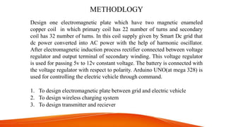
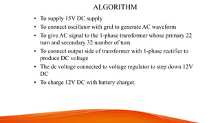
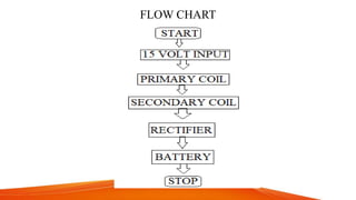
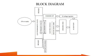
DESIGN AND DEVELOPMENT OF WIRELESS CHARGING
IN ELECTRIC VEHICLE
Guided by: Dr. P.K. Dhal
Professor/EEE Dept.
Submitted by:
NIKITASHANKER (8507)
SHRIKANT SINGH (8543)
CONTENT
• ABSTRACT
• INTRODUCTION
• OBJECTIVE
• METHODLOGY
• ALGORITHM
• FLOW CHART
• BLOCK DIAGRAM
• HARDWARE
• CONCLUSION
• REFERENCE
ABSTRACT
• Battery is connected to the electric vehicle has been considered as
the resource.
• It provides demand response to the service by controlling the
charging power.
• The smaller resource size requirement for charging an individual
electric vehicle is sufficient.
• Thus the charging service providers can minimize the charging cost
of an individual vehicle.
• Therefore the charging service provider benefits the vehicle
consumer by providing the demand response and regulation capacity.
INTRODUCTION
Electric vehicles have attracted significant attention because of
the potential to reduce carbon emissions in the transportation
sector. In order to encourage the use of electrical vehicles, the
governments of many countries give significant subsidies to electric
vehicels drivers due to the high cost of electrical vehicles and
chargers. From the perspective of the power systems, a battery-
connected electrical vehicles can act as a high-quality demand
response resource capable of rapidly reducing its charging power.
At the same time, electric vehicles are a flexible load that could be
controlled to provide regulation services to the electric. If a
communication infrastructure is in place, the electrical vehicles can
also provide highly valued flexibility in the power system using
the batteries of parked electrical vehicles.
OBJECTIVES
The main objective of this project is power transfer via airgap with
the help of electromagnetic induction proccess, It will charge the
electric vehicle’s battery without any cable connection from source to
battery. It can work properly within the limit of 3mm to 9mm airgap.
For this project following components are required:
• WIRELESS CHARGING
• ELECTROMAGNETIC PLATE
• ELECTRIC VEHICLE CHARGING SERVICE PROVIDER
• ELECTRIC VEHICLE
• FAST CHARGING SYSTEM
METHODLOGY
Design one electromagnetic plate which have two magnetic enameled
copper coil in which primary coil has 22 number of turns and secondary
coil has 32 number of turns. In this coil supply given by Smart Dc grid that
dc power converted into AC power with the help of harmonic oscillator.
After electromagnetic induction process rectifier connected between voltage
regulator and output terminal of secondary winding. This voltage regulator
is used for passing 5v to 12v constant voltage. The battery is connected with
the voltage regulator with respect to polarity. Arduino UNO(at mega 328) is
used for controlling the electric vehicle through command.
1. To design electromagnetic plate between grid and electric vehicle
2. To design wireless charging system
3. To design transmitter and reciever
ALGORITHM
• To supply 15V DC supply
• To connect oscillator with grid to generate AC waveform
• To give AC signal to the 1-phase transformer whose primary 22
turn and secondary 32 number of turn
• To connect output side of transformer with 1-phase rectifier to
produce DC voltage
• The dc voltage connected to voltage regulator to step down 12V
DC
• To charge 12V DC with battery charger.
FLOW CHART
BLOCK DIAGRAM
PRIMARY COIL (Transmitter Circuit)
TRANSMITTER HARDWARE
PRIMARY COIL SPECIFICATION
• Diameter of wire = 6mm copper type-magnet enamelled
• Diameter of coil (a)= 16.5cm, or 16.5/2.54= 6.5 inches
• Length of wire = 8.5cm, N1= numb of primary turn = 22
• L= (0.001*N1(a/2)^2)/(114a+254l) H
put the value in formula
L = 0.001×22× (0.165/2)2 / ((114×0.165) + (254×0.085)) H
L = 0.674 micro H
(Voltage Source, V dc- 30V Capacitors, C - 6.8 n F , L - 0.674 μ H)
F = 1/2*pi* sqrt (LC) = 0.5* 3.14* (0.674*10^-6 *6.8*10^-9)
SECNDARY COIL (Receiver circuit)
RECEIVER HARDWARE
RECEIVER CIRCUIT SPECIFICATION
• 16 awg wire (dia = 2mm)
• Coil diameter = 8cm= 0.08m
• numb of secondary winding turn = 32
• Length = 1 cm = 0.01m
L = 0.001 N2 (a/2)2 / (114a + 254l) H
Now we are applying the desired values for the coil,
L = 0.001×32× (0.08/2)2 / ((114×0.08) + (254×0.01)) H
L = 1.235 μ H
(Receiver coil, L: 1 .235 μ H)
MATHEMATICAL EXPRESSION FOR INDUCTIVE
COUPLING COFFICIENT
inductive coupling coefficient (m)= k* sqrt(L1+L2)
where design value of k = (0.1 to 0.5)
• m= 0.5 * sqrt(0.674+1.235) = 0.9545
• m= 0.4 * sqrt(0.674+1.235) = 0.5527
• m= 0.45*sqrt(0.674+1.235) = 0.6217
• m= 0.46*sqrt(0.674+1.235) = 0.6356
• m= 0.47*sqrt(0.674+1.235) = 0.6493
• m= 0.48*sqrt(0.674+1.235) = 0.6632
• m= 0.49*sqrt(0.674+1.235) = 0.6770
The above coefficient value depend upon the airgap between primay
and secondary winding.
HARDWARE
HARDWARE PREPRATION
HARDWARE
VIEW OF HARDWARE
HARDWARE
READY HARWARE
OUTPUT WITH RESPECT TO AIRGAP
COMPONENT SPECIFICATION
Transmitter section:
Voltage Source, V dc: 30V
Capacitors, C : 6.8 n F
Radio Frequency Choke,L1: 8.6 μ H
Radio Frequency Choke, L2: 8.6 μ H
Transmitter coil, L: 0.674 μ H
Resistors:
R1: 1K R2: 10 K R3: 94 ohm R4: 94
ohm R5: 10 K
Diodes:
D1: D4148 D2: D4148
Transistors:
MOSFET, Q1: IRF540
MOSFET, Q2: IRF540
Receiver Section:
Diode, D1, D2, D3, D4: D4007
Resistor, R 1k ohm Voltage
Regulator IC: IC LM 7805
Receiver coil, L: 1 .235 μ H
Capacitors:
C1: 6.8 n F C2: 220 μ F
WORKING PRINCIPLE
Basic principle of wireless charging is, in wireless charging there are
transmitter and receiver. DC supply from the smart-grid is converted
into high frequency alternating current. This high frequency ac
supplied to transmitter coil which further creates alternating magnetic
field that cuts the receiver coil and produces ac power output in
receiver coil. Then finally this ac power at receiver side rectified to dc
and fed to battery through voltage regulator. It’s not as efficient as a
direct cable connection between the battery and wire. Wireless
charging is around 60% - 70% efficient and it is done through a
wireless connection. But for day – to –day use just lining up the coils
and letting election electromagnetism do the rest is the simple value
proportion at the heart of wireless charging.
ADVANTAGES
 Easy to design because it can be easily connected reciver
circuit through the charging point.
 Increase efficiency of vehicles.
 Increase regulation of vehicles.
 Increase the sell of eletrical vehicles.
 It can be implimented on existing road.
CONCLUSION
We belive that charging can provide us with a convincing value
proposition when applied onto the Electric Vehicle market. We
aim to break into the market with as many charging station as
possible and gradually transform ourselves from a technology
solution provider to a charging service provider for all Electric
Vehicles.
REFERENCES
I. Department of Electrical and Computer Engineering,
University of Michigan 1301 Beal Ave., Ann Arbor, MI
48109 Phone: (805)698-2584, Fax: (734)763-8041, E-mail:
mikehaf@umich.edu
II. Toyota Technical Center, Toyota Engineering and
Manufacturing North America 1555 Woodridge Ave., Ann
Arbor, MI 48105 Phone: (617)452-2275, Fax: (734)995-
3053, E-mail: lorenzo.caminiti@tema.toyota.com
III. Department of Mechanical Engineering, Massachusetts
Institute of Technology 77 Massachusetts Ave., Cambridge,
MA 02139 Phone: (734)995-9330, Fax: (617)258-6156,
.
Thank you

wire less charging in electric vehicles

  • 1.
    DESIGN AND DEVELOPMENTOF WIRELESS CHARGING IN ELECTRIC VEHICLE Guided by: Dr. P.K. Dhal Professor/EEE Dept. Submitted by: NIKITASHANKER (8507) SHRIKANT SINGH (8543)
  • 2.
    CONTENT • ABSTRACT • INTRODUCTION •OBJECTIVE • METHODLOGY • ALGORITHM • FLOW CHART • BLOCK DIAGRAM • HARDWARE • CONCLUSION • REFERENCE
  • 3.
    ABSTRACT • Battery isconnected to the electric vehicle has been considered as the resource. • It provides demand response to the service by controlling the charging power. • The smaller resource size requirement for charging an individual electric vehicle is sufficient. • Thus the charging service providers can minimize the charging cost of an individual vehicle. • Therefore the charging service provider benefits the vehicle consumer by providing the demand response and regulation capacity.
  • 4.
    INTRODUCTION Electric vehicles haveattracted significant attention because of the potential to reduce carbon emissions in the transportation sector. In order to encourage the use of electrical vehicles, the governments of many countries give significant subsidies to electric vehicels drivers due to the high cost of electrical vehicles and chargers. From the perspective of the power systems, a battery- connected electrical vehicles can act as a high-quality demand response resource capable of rapidly reducing its charging power. At the same time, electric vehicles are a flexible load that could be controlled to provide regulation services to the electric. If a communication infrastructure is in place, the electrical vehicles can also provide highly valued flexibility in the power system using the batteries of parked electrical vehicles.
  • 5.
    OBJECTIVES The main objectiveof this project is power transfer via airgap with the help of electromagnetic induction proccess, It will charge the electric vehicle’s battery without any cable connection from source to battery. It can work properly within the limit of 3mm to 9mm airgap. For this project following components are required: • WIRELESS CHARGING • ELECTROMAGNETIC PLATE • ELECTRIC VEHICLE CHARGING SERVICE PROVIDER • ELECTRIC VEHICLE • FAST CHARGING SYSTEM
  • 6.
    METHODLOGY Design one electromagneticplate which have two magnetic enameled copper coil in which primary coil has 22 number of turns and secondary coil has 32 number of turns. In this coil supply given by Smart Dc grid that dc power converted into AC power with the help of harmonic oscillator. After electromagnetic induction process rectifier connected between voltage regulator and output terminal of secondary winding. This voltage regulator is used for passing 5v to 12v constant voltage. The battery is connected with the voltage regulator with respect to polarity. Arduino UNO(at mega 328) is used for controlling the electric vehicle through command. 1. To design electromagnetic plate between grid and electric vehicle 2. To design wireless charging system 3. To design transmitter and reciever
  • 7.
    ALGORITHM • To supply15V DC supply • To connect oscillator with grid to generate AC waveform • To give AC signal to the 1-phase transformer whose primary 22 turn and secondary 32 number of turn • To connect output side of transformer with 1-phase rectifier to produce DC voltage • The dc voltage connected to voltage regulator to step down 12V DC • To charge 12V DC with battery charger.
  • 8.
  • 9.
  • 10.
  • 11.
  • 12.
    PRIMARY COIL SPECIFICATION •Diameter of wire = 6mm copper type-magnet enamelled • Diameter of coil (a)= 16.5cm, or 16.5/2.54= 6.5 inches • Length of wire = 8.5cm, N1= numb of primary turn = 22 • L= (0.001*N1(a/2)^2)/(114a+254l) H put the value in formula L = 0.001×22× (0.165/2)2 / ((114×0.165) + (254×0.085)) H L = 0.674 micro H (Voltage Source, V dc- 30V Capacitors, C - 6.8 n F , L - 0.674 μ H) F = 1/2*pi* sqrt (LC) = 0.5* 3.14* (0.674*10^-6 *6.8*10^-9)
  • 13.
  • 14.
  • 15.
    RECEIVER CIRCUIT SPECIFICATION •16 awg wire (dia = 2mm) • Coil diameter = 8cm= 0.08m • numb of secondary winding turn = 32 • Length = 1 cm = 0.01m L = 0.001 N2 (a/2)2 / (114a + 254l) H Now we are applying the desired values for the coil, L = 0.001×32× (0.08/2)2 / ((114×0.08) + (254×0.01)) H L = 1.235 μ H (Receiver coil, L: 1 .235 μ H)
  • 16.
    MATHEMATICAL EXPRESSION FORINDUCTIVE COUPLING COFFICIENT inductive coupling coefficient (m)= k* sqrt(L1+L2) where design value of k = (0.1 to 0.5) • m= 0.5 * sqrt(0.674+1.235) = 0.9545 • m= 0.4 * sqrt(0.674+1.235) = 0.5527 • m= 0.45*sqrt(0.674+1.235) = 0.6217 • m= 0.46*sqrt(0.674+1.235) = 0.6356 • m= 0.47*sqrt(0.674+1.235) = 0.6493 • m= 0.48*sqrt(0.674+1.235) = 0.6632 • m= 0.49*sqrt(0.674+1.235) = 0.6770 The above coefficient value depend upon the airgap between primay and secondary winding.
  • 17.
  • 18.
  • 19.
  • 20.
  • 21.
  • 22.
  • 23.
  • 24.
    COMPONENT SPECIFICATION Transmitter section: VoltageSource, V dc: 30V Capacitors, C : 6.8 n F Radio Frequency Choke,L1: 8.6 μ H Radio Frequency Choke, L2: 8.6 μ H Transmitter coil, L: 0.674 μ H Resistors: R1: 1K R2: 10 K R3: 94 ohm R4: 94 ohm R5: 10 K Diodes: D1: D4148 D2: D4148 Transistors: MOSFET, Q1: IRF540 MOSFET, Q2: IRF540 Receiver Section: Diode, D1, D2, D3, D4: D4007 Resistor, R 1k ohm Voltage Regulator IC: IC LM 7805 Receiver coil, L: 1 .235 μ H Capacitors: C1: 6.8 n F C2: 220 μ F
  • 25.
    WORKING PRINCIPLE Basic principleof wireless charging is, in wireless charging there are transmitter and receiver. DC supply from the smart-grid is converted into high frequency alternating current. This high frequency ac supplied to transmitter coil which further creates alternating magnetic field that cuts the receiver coil and produces ac power output in receiver coil. Then finally this ac power at receiver side rectified to dc and fed to battery through voltage regulator. It’s not as efficient as a direct cable connection between the battery and wire. Wireless charging is around 60% - 70% efficient and it is done through a wireless connection. But for day – to –day use just lining up the coils and letting election electromagnetism do the rest is the simple value proportion at the heart of wireless charging.
  • 26.
    ADVANTAGES  Easy todesign because it can be easily connected reciver circuit through the charging point.  Increase efficiency of vehicles.  Increase regulation of vehicles.  Increase the sell of eletrical vehicles.  It can be implimented on existing road.
  • 27.
    CONCLUSION We belive thatcharging can provide us with a convincing value proposition when applied onto the Electric Vehicle market. We aim to break into the market with as many charging station as possible and gradually transform ourselves from a technology solution provider to a charging service provider for all Electric Vehicles.
  • 28.
    REFERENCES I. Department ofElectrical and Computer Engineering, University of Michigan 1301 Beal Ave., Ann Arbor, MI 48109 Phone: (805)698-2584, Fax: (734)763-8041, E-mail: mikehaf@umich.edu II. Toyota Technical Center, Toyota Engineering and Manufacturing North America 1555 Woodridge Ave., Ann Arbor, MI 48105 Phone: (617)452-2275, Fax: (734)995- 3053, E-mail: lorenzo.caminiti@tema.toyota.com III. Department of Mechanical Engineering, Massachusetts Institute of Technology 77 Massachusetts Ave., Cambridge, MA 02139 Phone: (734)995-9330, Fax: (617)258-6156,
  • 29.