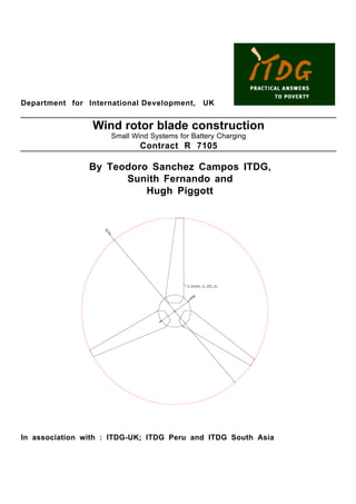
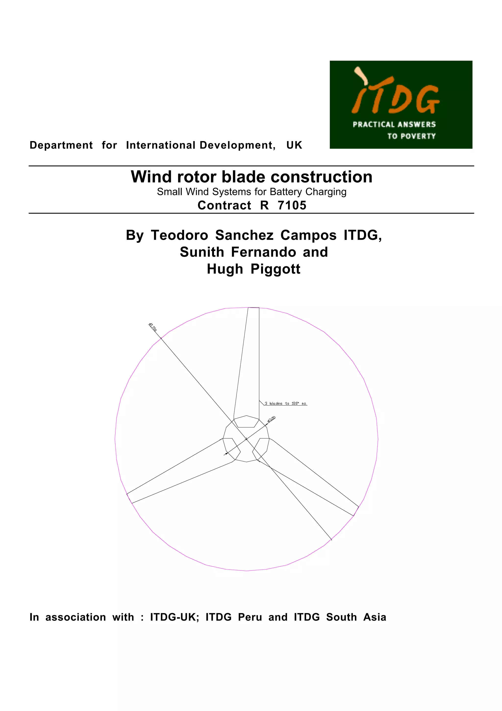
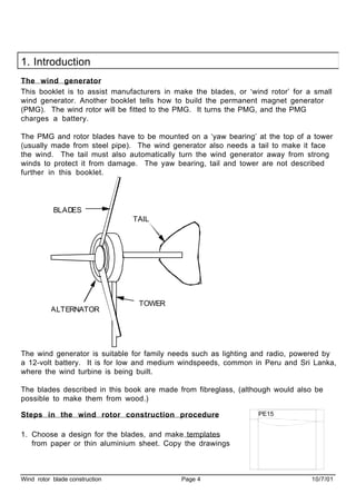
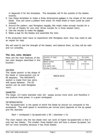
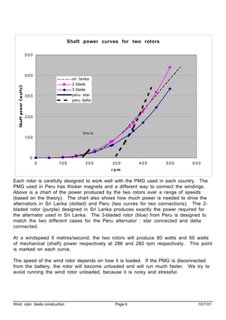
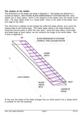
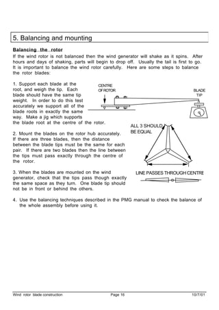
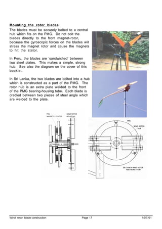
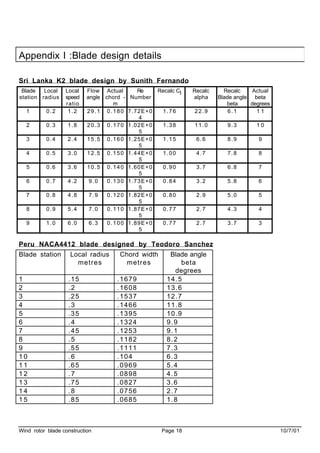
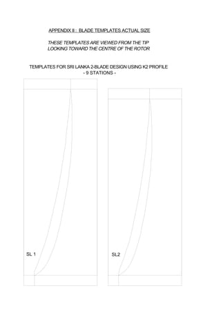
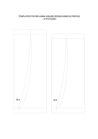
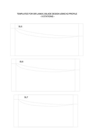
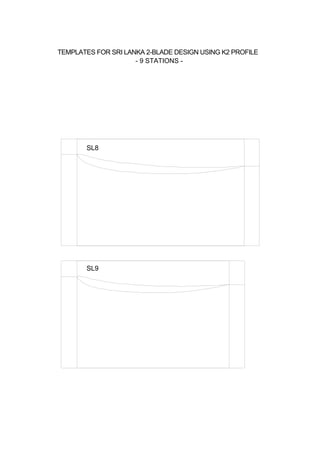
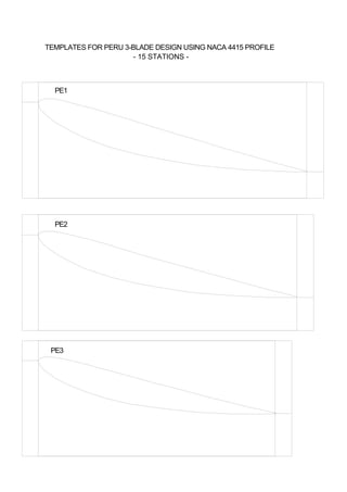
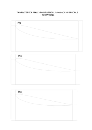
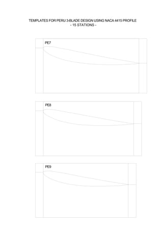
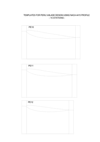
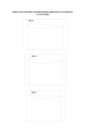
Dimensional and Constructional Details of Components, Fundamentals of TNM Met...IJERA Editor
For the improvement in thermal design of squirrel cage induction (SCIM) motor, it is essential to know details
of the methods for evaluation of thermal distribution in a SCIM motor. A presentation of various details of
methods of basics of heat transfer that occur in a SCIM motor is done in this report. SCIM motors have wide
applications and thus their construction is completely influenced by the starting characteristics specified by the
operating loads. General constraints of a motor and specification of 30 KW motor are presented in this report as
a case study of constraints. As the next step the Thermal Network Method (TNM) has been explained.
Design and Analysis of Composite Propeller Blade for AircraftIJERA Editor
Fiber reinforced composites is used for twin blade propeller because of its high strength, low temperature applications. Fiber has to be oriented in the loading direction while designing the composite propeller blade. The blade geometry and design are more complex involving many controlling parameters. In the present work a methodology to design a composite propeller to analyze its strength and deformation using ANSYS software. The weight of the composite blade is reduced compared to wooden blade by adopting the shell model. The present work is to carryout the static analysis of composite propeller which is a combination CFRP (Carbon Fiber Reinforced Plastics) and epoxy resin materials. In order to evaluate the effectiveness of the composite blade over wooden stress analysis is performed on both the blades. To define the orientation and number of layers in the composite blade ANSYS classic software is used. From the results, the stresses of composite propeller obtained in static analysis are within the allowable stress limit. The deflection of the composite blade is less compared to the wooden blade.
GEOMETRIC OPTIMIZATION AND MANUFACTURING PROCESS OF SIX CYLINDER DIESEL ENGIN...Ijripublishers Ijri
The crankshaft is that part of an engine which translates reciprocating linear piston motion into rotation. To convert the
reciprocating motion into rotation, the crankshaft has "crank" or "crankpins", additional bearing surfaces whose axis is
offset from that of the crank, to which the "big ends" of the connecting rods from each cylinder attach.
The aim of the project work is to optimize the geometry shape of 6-cylinder diesel engine crank shaft to reduce the failures
and to reduce the weight. And also this project work will provide the brief explanation of manufacturing process.
Initially literature survey and data collection will be done to understand methodology.
Design calculations will be done to get parameters of object for drafting.
3D model will be prepared according to the obtained parameters.
Analysis will be conducted on crank shaft to rectify failures by optimizing geometric shape. Also best material will be
suggested by analyzing and comparing results with the variation of materials.
Mold tool design will be done and assembly will be prepared according to that.
Cnc program will be prepared for die set using cam
Review Paper on Computer Aided Design & Analysis of Rotor Shaft of a RotavatorIJSRD
The intent of this paper is to study the various forces and stress acting on a rotor shaft of a standard rotavator which is subjected to transient loading. The standard models of rotavator, having a progressive cutting sequence was considered for the study and analysis. The study was extended to various available models having different cutting blade arrangement. The study was carried on different papers and identifies the various forces acting on a Rotor shaft of a rotavator. The positions of the torque and forces applied are varied according to the model considered. The response was obtained by considering the angle of twist and equivalent stress on the rotor shaft. This paper presented a methodology for conducting transient analysis of rotor shaft of a rotavator,
International Journal of Computational Engineering Research (IJCER) is dedicated to protecting personal information and will make every reasonable effort to handle collected information appropriately. All information collected, as well as related requests, will be handled as carefully and efficiently as possible in accordance with IJCER standards for integrity and objectivity.
Analysis of bending strength of bevel gear by FEMAM Publications
In bevel gear will have a tangential load, radial load and axial load due to the speed and torque .This will be a
transient phenomenon and will need careful stress analysis for determining life of the gear. In gear design, the Mechanism will
be more Challenging as it should transmit high torque. All gears are not to be used for such high torque applications due to their
low capacity and strength. Bevel gears are used in differential drives, which can transmit power to two axles spinning at different
speeds, such as those on a cornering automobile, hand drill, to redirect the shaft from the horizontal gas turbine engine to the
vertical rotor. In this paper a comparison between Lewis equation and Ansys workbench is done.
International Journal of Engineering Research and Applications (IJERA) is an open access online peer reviewed international journal that publishes research and review articles in the fields of Computer Science, Neural Networks, Electrical Engineering, Software Engineering, Information Technology, Mechanical Engineering, Chemical Engineering, Plastic Engineering, Food Technology, Textile Engineering, Nano Technology & science, Power Electronics, Electronics & Communication Engineering, Computational mathematics, Image processing, Civil Engineering, Structural Engineering, Environmental Engineering, VLSI Testing & Low Power VLSI Design etc.
Why Is Your BMW X3 Hood Not Responding To Release CommandsDart Auto
Experiencing difficulty opening your BMW X3's hood? This guide explores potential issues like mechanical obstruction, hood release mechanism failure, electrical problems, and emergency release malfunctions. Troubleshooting tips include basic checks, clearing obstructions, applying pressure, and using the emergency release.
Comprehensive program for Agricultural Finance, the Automotive Sector, and Empowerment . We will define the full scope and provide a detailed two-week plan for identifying strategic partners in each area within Limpopo, including target areas.:
1. Agricultural : Supporting Primary and Secondary Agriculture
• Scope: Provide support solutions to enhance agricultural productivity and sustainability.
• Target Areas: Polokwane, Tzaneen, Thohoyandou, Makhado, and Giyani.
2. Automotive Sector: Partnerships with Mechanics and Panel Beater Shops
• Scope: Develop collaborations with automotive service providers to improve service quality and business operations.
• Target Areas: Polokwane, Lephalale, Mokopane, Phalaborwa, and Bela-Bela.
3. Empowerment : Focusing on Women Empowerment
• Scope: Provide business support support and training to women-owned businesses, promoting economic inclusion.
• Target Areas: Polokwane, Thohoyandou, Musina, Burgersfort, and Louis Trichardt.
We will also prioritize Industrial Economic Zone areas and their priorities.
Sign up on https://profilesmes.online/welcome/
To be eligible:
1. You must have a registered business and operate in Limpopo
2. Generate revenue
3. Sectors : Agriculture ( primary and secondary) and Automative
Women and Youth are encouraged to apply even if you don't fall in those sectors.
Core technology of Hyundai Motor Group's EV platform 'E-GMP'Hyundai Motor Group
What’s the force behind Hyundai Motor Group's EV performance and quality?
Maximized driving performance and quick charging time through high-density battery pack and fast charging technology and applicable to various vehicle types!
Discover more about Hyundai Motor Group’s EV platform ‘E-GMP’!
𝘼𝙣𝙩𝙞𝙦𝙪𝙚 𝙋𝙡𝙖𝙨𝙩𝙞𝙘 𝙏𝙧𝙖𝙙𝙚𝙧𝙨 𝙞𝙨 𝙫𝙚𝙧𝙮 𝙛𝙖𝙢𝙤𝙪𝙨 𝙛𝙤𝙧 𝙢𝙖𝙣𝙪𝙛𝙖𝙘𝙩𝙪𝙧𝙞𝙣𝙜 𝙩𝙝𝙚𝙞𝙧 𝙥𝙧𝙤𝙙𝙪𝙘𝙩𝙨. 𝙒𝙚 𝙝𝙖𝙫𝙚 𝙖𝙡𝙡 𝙩𝙝𝙚 𝙥𝙡𝙖𝙨𝙩𝙞𝙘 𝙜𝙧𝙖𝙣𝙪𝙡𝙚𝙨 𝙪𝙨𝙚𝙙 𝙞𝙣 𝙖𝙪𝙩𝙤𝙢𝙤𝙩𝙞𝙫𝙚 𝙖𝙣𝙙 𝙖𝙪𝙩𝙤 𝙥𝙖𝙧𝙩𝙨 𝙖𝙣𝙙 𝙖𝙡𝙡 𝙩𝙝𝙚 𝙛𝙖𝙢𝙤𝙪𝙨 𝙘𝙤𝙢𝙥𝙖𝙣𝙞𝙚𝙨 𝙗𝙪𝙮 𝙩𝙝𝙚 𝙜𝙧𝙖𝙣𝙪𝙡𝙚𝙨 𝙛𝙧𝙤𝙢 𝙪𝙨.
Over the 10 years, we have gained a strong foothold in the market due to our range's high quality, competitive prices, and time-lined delivery schedules.
Symptoms like intermittent starting and key recognition errors signal potential problems with your Mercedes’ EIS. Use diagnostic steps like error code checks and spare key tests. Professional diagnosis and solutions like EIS replacement ensure safe driving. Consult a qualified technician for accurate diagnosis and repair.
Fleet management these days is next to impossible without connected vehicle solutions. Why? Well, fleet trackers and accompanying connected vehicle management solutions tend to offer quite a few hard-to-ignore benefits to fleet managers and businesses alike. Let’s check them out!
5 Warning Signs Your BMW's Intelligent Battery Sensor Needs AttentionBertini's German Motors
IBS monitors and manages your BMW’s battery performance. If it malfunctions, you will have to deal with an array of electrical issues in your vehicle. Recognize warning signs like dimming headlights, frequent battery replacements, and electrical malfunctions to address potential IBS issues promptly.
"Trans Failsafe Prog" on your BMW X5 indicates potential transmission issues requiring immediate action. This safety feature activates in response to abnormalities like low fluid levels, leaks, faulty sensors, electrical or mechanical failures, and overheating.
What Does the PARKTRONIC Inoperative, See Owner's Manual Message Mean for You...Autohaus Service and Sales
Learn what "PARKTRONIC Inoperative, See Owner's Manual" means for your Mercedes-Benz. This message indicates a malfunction in the parking assistance system, potentially due to sensor issues or electrical faults. Prompt attention is crucial to ensure safety and functionality. Follow steps outlined for diagnosis and repair in the owner's manual.
What Exactly Is The Common Rail Direct Injection System & How Does It WorkMotor Cars International
Learn about Common Rail Direct Injection (CRDi) - the revolutionary technology that has made diesel engines more efficient. Explore its workings, advantages like enhanced fuel efficiency and increased power output, along with drawbacks such as complexity and higher initial cost. Compare CRDi with traditional diesel engines and discover why it's the preferred choice for modern engines.
In this presentation, we have discussed a very important feature of BMW X5 cars… the Comfort Access. Things that can significantly limit its functionality. And things that you can try to restore the functionality of such a convenient feature of your vehicle.
Ever been troubled by the blinking sign and didn’t know what to do?
Here’s a handy guide to dashboard symbols so that you’ll never be confused again!
Save them for later and save the trouble!
1. Department for International Development, UK
Wind rotor blade construction
Small Wind Systems for Battery Charging
Contract R 7105
By Teodoro Sanchez Campos ITDG,
Sunith Fernando and
Hugh Piggott
In association with : ITDG-UK; ITDG Peru and ITDG South Asia
2. Wind rotor blade construction Page 2 10/7/01
This research on small wind energy systems for battery charging is the result of a
collaborative effort involving numerous contributors.
The project was managed by Intermediate Technology (known as The Intermediate
Technology Development Group or ITDG) under a contract to the UK Department for
International Development.
The overall international project was co-ordinated by Dr Smail Khennas, Senior
Energy Specialist from ITDG with support from Simon Dunnett. The field work in Peru
and Sri Lanka were respectively managed by Teodoro Sanchez and Rohan Senerath.
Teodoro Sanchez Campos (ITDG Peru), Sunith Fernando (Sri Lanka) and Hugh Piggott (a
UK technical consultant for the project), are the authors of this booklet on the rotor
blade manufacture.
The views expressed in this report are those of the authors and do not necessarily
represent the views of the sponsoring organisations, the reviewers or the other
contributors.
This diagram shows the shape of a blade pattern.
3. Wind rotor blade construction Page 3 10/7/01
Wind rotor blade construction
Small Wind Systems for Battery Charging
CONTENTS
1. Introduction........................................................................................................4
The wind generator 4
Steps in the wind rotor construction procedure 4
The two rotor designs 5
The shapes of the blades 7
2. Templates, Patterns and Moulds .........................................................................8
Templates 8
Patterns 8
Making two separate patterns 9
Finishing of the surface. 1 0
An alternative idea : making patterns from metal 1 0
Making the moulds 1 1
3. Blade construction............................................................................................1 3
The procedure in Peru is as follows. 1 3
4. Testing for strength.........................................................................................1 5
5. Balancing and mounting.....................................................................................1 6
Balancing the rotor 1 6
Mounting the rotor blades 1 7
Appendix I :Blade design details.............................................................................1 8
Sri Lanka K2 blade design by Sunith Fernando 1 8
Peru NACA4412 blade designed by Teodoro Sanchez 1 8
4. Wind rotor blade construction Page 4 10/7/01
1. Introduction
The wind generator
This booklet is to assist manufacturers in make the blades, or ‘wind rotor’ for a small
wind generator. Another booklet tells how to build the permanent magnet generator
(PMG). The wind rotor will be fitted to the PMG. It turns the PMG, and the PMG
charges a battery.
The PMG and rotor blades have to be mounted on a ‘yaw bearing’ at the top of a tower
(usually made from steel pipe). The wind generator also needs a tail to make it face
the wind. The tail must also automatically turn the wind generator away from strong
winds to protect it from damage. The yaw bearing, tail and tower are not described
further in this booklet.
BLADES
ALTERNATOR
TAIL
TOWER
The wind generator is suitable for family needs such as lighting and radio, powered by
a 12-volt battery. It is for low and medium windspeeds, common in Peru and Sri Lanka,
where the wind turbine is being built.
The blades described in this book are made from fibreglass, (although would also be
possible to make them from wood.)
Steps in the wind rotor construction procedure
1. Choose a design for the blades, and make templates
from paper or thin aluminium sheet. Copy the drawings
PE15
5. Wind rotor blade construction Page 5 10/7/01
in Appendix II for the templates. The templates will fit the outside of the blades
exactly.
2. Use these templates to make a three dimensional pattern in the shape of the actual
blade. One can carve a pattern from wood. Or metal sheet or foam could be used
instead.
3. Around the pattern, cast fibreglass moulds. We might make enough moulds for a
full set of blades for one rotor (three moulds for a three bladed rotor).
4. Use the moulds to make the blades.
5. Make a hub for the blades and assemble the rotor.
If the production team have no experience with fibreglass resin, they may need to ask
an expert for help.
We will need to test the strength of the blades, and balance them, so they will be safe
and run smoothly.
The two rotor designs
Here are the main features of the
two rotor designs described in this
booklet:-
SECTION
The ‘blade section’ is the shape of
the blade in cross-section (cut at
90 degrees). The NACA4412
section is made from two skins
with space between. The K2
section can be solid fibreglass
resin.
DIAMETER
The larger, 2.0 metre diameter rotor will sweep across more wind, and therefore it
can produce more power, in a given windspeed.
TIP SPEED RATIO
The ‘tip-speed-ratio’ is the speed at which the blade tip should run compared to the
windspeed. The shaft speed in revolutions per minute (rpm) depends on the tip speed
and the diameter.
Rpm = windspeed x tip-speed-ratio x 60 / (diameter x Π)
The main reason why the two blade rotor can work at higher tip-speed-ratio is that it
only has two blades. The smaller, three bladed rotor will have a slower tip-speed, but
will run more smoothly because it has three blades.
Country of origin Peru Sri Lanka
Designer Teodoro Sanchez Sunith Fernando
Blade section NACA 4412 K2
Diameter 1.7metres 2.0metres
Tip speed ratio 5 6
Number of blades 3 2
NACA 4412
K2
6. Wind rotor blade construction Page 6 10/7/01
Each rotor is carefully designed to work well with the PMG used in each country. The
PMG used in Peru has thicker magnets and a different way to connect the windings.
Above is a chart of the power produced by the two rotors over a range of speeds
(based on the theory). The chart also shows how much power is needed to drive the
alternators in Sri Lanka (dotted) and Peru (two curves for two connections). The 2-
bladed rotor (purple) designed in Sri Lanka produces exactly the power required for
the alternator used in Sri Lanka. The 3-bladed rotor (blue) from Peru is designed to
match the two different cases for the Peru alternator : star connected and delta
connected.
At a windspeed 5 metres/second, the two rotors will produce 80 watts and 60 watts
of mechanical (shaft) power respectively at 286 and 280 rpm respectively. This point
is marked on each curve.
The speed of the wind rotor depends on how it is loaded. If the PMG is disconnected
from the battery, the rotor will become unloaded and will run much faster. We try to
avoid running the wind rotor unloaded, because it is noisy and stressful.
Shaft power curves for two rotors
0
1 0 0
2 0 0
3 0 0
4 0 0
5 0 0
0 1 0 0 2 0 0 3 0 0 4 0 0 5 0 0 6 0 0
r p m
sri lanka
2 blade
3 blade
peru star
peru delta
5m/s
7. Wind rotor blade construction Page 7 10/7/01
The shapes of the blades
The dimensions of the blades are listed in Appendix I. The blades are defined at a
number of ‘stations’. SEE FIGURE ‘BLADE DIMENSIONS AT STATIONS’ BELOW. Each
station has a ‘local radius’, which is the distance of the station from the centre of the
rotor. For each station there is a ‘chord width’, which is the width of the blade, from
one edge to the other.
The ‘chord line’ is defined as the longest line within the blade section, and it joins the
leading edge to the trailing edge. The ‘blade angle’ (beta) is the angle between the
chord line and the plane in which the rotor spins. Given the local radius, chord width
and blade angle at each station, we can construct the shape of the whole blade. This
is done in Appendix II.
At the root, the shape of the blade changes from an airfoil section into a shape which
is suitable for the hub assembly
BLADE
ANGLE
BETA
CHORD
WIDTH
LOCAL RADIUS
CENTRE OF
ROTOR
BLADE DIMENSIONS AT STATIONS
EXAMPLE : PERU 3 BLADED ROTOR
TIP
ROOT
8. Wind rotor blade construction Page 8 10/7/01
2. Templates, Patterns and Moulds
Templates
Choose a blade design and make
photocopies of the templates in Appendix II.
Either cut out these copies and use paper
templates to make the pattern, or
alternatively use thin aluminium sheet for
the templates.
Transfer the shape to the aluminium sheet
using carbon paper to trace it, and/or using
a punch through the paper to mark the
aluminium with the lines.
Each template drawing has 3 areas within it:
1. A blade section (remove this)
2. A front template A
3. A back template B (turn it over and use it when carving the back of the pattern)
The vertical lines on the template show the width of the workpiece for the pattern
after it has been tapered. The angle of the blade section is the exact blade angle. The
top edge of template A is exactly 10mm from the top surface of the blade. The
bottom of template ‘B’ is 60mm below the top surface.
Patterns
The pattern is an object which is exactly the shape of the blade. Use it to make
moulds for the blades. There are various ways to make a pattern. It can be made
from wood. This is normal. However, wood can warp, and change its shape. It is
important to choose a very stable wood. In Peru they have used Coava, which is a hard
wood with good stability.
Sunith Fernando in Sri Lanka tried a wooden pattern initially but warping became a
problem. “For K2, which is a slender profile, I made the pattern out of two materials.
First I got a steel sheet (~ 0.8 mm thick) rolled into K2 outer profile – more or less,
and then filled the inside with a paste that we use to fill up dents of automobile
bodywork (we call it Cataloy paste). I used the paste to fill up the outer profile also as
a thin layer. Then I filed the hardened cataloy paste to the required profile.
Thereafter, I got the blade pattern cast in aluminium. It is the aluminium pattern that I
gave for fibreglass work.”
For the construction of the wooden pattern follow this procedure:
a). - Buy a rectangular block of wood 45mm x 165mm x 700 mm. The wood should be
dry enough before starting the work of carving.
PE15
FRONT
TEMPLATE 'A'
BACK
TEMPLATE 'B'
WIDTH OF
WORKPIECE
TRAILING EDGE
LEADING
EDGE
9. Wind rotor blade construction Page 9 10/7/01
b)- Mark the position of each station. Then draw
two lines along the wider faces using the
‘workpiece width’ on the templates, and cut the
wood to the correct width at each station.
c)- Use the templates to mark a leading edge line
and a trailing edge line. These are the lines where
the two moulds will meet. Here is how to mark
these lines: The top of the workpiece should be
60mm above the level of the bench. The right
hand side of each template ‘B’ is the trailing edge.
Place it on the bench, against the left hand side of
the workpiece as shown, and mark the trailing
edge. Do this at each station and then do the
same for the leading edge.
d)-Then carve the curved shape of the blade
pattern, checking very carefully with the
templates at each station.
The templates in
Appendix II are
printed in such a
way that one
should look at
them from the tip
of the blade
inward. Place the
template over the
workpiece at its
station. When the pattern is finished, the top edge of the template should be exactly
level, and the leading and trailing edge lines should meet the lines drawn earlier on the
sides of the workpiece.
Making two separate patterns
The moulds for the blades will made in two pieces:
one for each side of the blade. It is possible
therefore to use two patterns instead of one, one
for each mould. If there are two patterns, they do
not have to be thin, like the blade itself. They can
be made from big thick pieces of wood, which will
not easily warp.
TAPER THE
WORKPIECE TO
THE CORRECT
WIDTH
DRAW LINES
FORTHEEDGES
DRAW
A LINE
AROUND THE
WORKPIECE AT
EACH STATION
USE THE
TEMPLATES TO
MARK THE
CORRECT WIDTH
AT EACH STATION
SET THE
WORKPIECE
TOP LEVEL,
60mm ABOVE
THEBENCH
USE TEMPLATE 'B' STANDING ON THE
BENCH TO MARK THE EDGES FOR EACH
STATION
10. Wind rotor blade construction Page 10 10/7/01
The photo (last page) shows a pattern being carved from a wooden workpiece which
has been built up out of three pieces of wood glued together.
Finishing of the surface.
The finishing of the surface is an important feature because the quality of the
surface of the blades will depend on that, therefore it is recommended to use some
substance to feel tiny imperfections of wood, and later polish the surface until it looks
as regular as possible, paint the pattern and polish again until it is soft enough or good
enough to be used as a pattern.
An alternative idea : making patterns from metal
First I must state that this idea has not been tried at the time of writing. It is
possible to make patterns for the blades using sheet metal wrapped over metal
formers (support pieces). Make two patterns - one for each mould. One is for the
back of the blade, and one is for the front.
Cut out the
support pieces
using the
template
shapes in
Appendix II.
They will be
used to
support the
pattern
surface sheet,
rather than
just to check
its shape.
Glue all the support pieces
onto a level base at the
correct spacings, and then
glue a surface sheet down
onto them tightly.
There are yet more, other
ways to make the
patterns. It is possible to
make them from foam, cut
with a hot wire. This method is popular with model makers.
Probably the simplest method is to carve them from wood, as described above.
SUPPORTPIECE
FOR PATTERN A
SUPPORTPIECE
FOR PATTERN B
(TURN OVER)
SUPPORT PIECES
BASE
TRAILING EDGE
LEADINGEDGE
11. Wind rotor blade construction Page 11 10/7/01
Making the moulds
In Peru, the moulds were
manufactured in fibreglass. “The
mould is done in two pieces,
therefore it is convenient to be
careful with splitting the blade
into two parts, (or with the
splitting line)
“The moulds can be of different
materials, resin and fibreglass is
always a good option, however it
does not have a long life, it is
expected that each mould can be
useful to produce up to 50 or 60
units of blades.
“Therefore in some cases it would be preferable to use metal ones. Aluminium is a
good alternative and it is widely used for fibreglass products.”
The blade root needs to be shaped to mount easily onto the wind generator. In Peru
the root shape is as shown above. All three blade roots are clamped between two
steel plates. The transition between the root (mounting portion) and the blade (airfoil
12. Wind rotor blade construction Page 12 10/7/01
section portion) is to be made smoothly. Avoid using sharp curves which would weaken
the fibreglass.
The moulds for the Sri Lankan blades are shown to
the right. They were made in fibreglass on an
aluminium pattern. One side of the K2 mould is
convex, because the upwind side of the blade is to be
concave.
The two halves of the mould
When making the first half of the mould, use only one
face of the pattern. Make a flat surface around the
edges of the pattern which will later become the
faces where the two moulds will meet. This can be
done with fibreglass resin, wood or plasticene or any
material which is easy to work. Take care to follow
the edges of the pattern very exactly. When the
first half mould has been made one can destroy this
flat surface.
It is a good idea to make two holes in the flat surface
at the edge of the first half, so that the second half
will have two lumps. Later, we
will fit the two halves of the
blade together inside the
moulds. If the lumps are in
the holes then the two halves
are correctly lined up.
When making the second half
of the mould, place the first
half against the other side of
the pattern. Polish the flat
surface around the edges, in
the same way as the pattern,
so that the fibreglass resin
will not stick to it. Make the
second half of the mould
cover the pattern and also the
flat surface, so that the two moulds fit each other perfectly.
If there will be two separate patterns for the two halves of the mould, take great care
that the final blade will be the correct shape when the halves are put together. It
would be easy to alter the thickness of the blade by inaccurate patterns.
13. Wind rotor blade construction Page 13 10/7/01
3. Blade construction
The procedure in Peru is as
follows.
a) The mould should very clean
before using the resin and fibreglass.
Use alcohol or other solvent to clean it.
b) Use some substance to facilitate
the mould separation from the blade
when it is ready.
c) Paint a thin layer of resin in each
side of the mould, then a layer of
fibreglass (approximately 1mm).
d) Again a layer of resin on top of
the fibreglass, and so on until there is
approximately 3 to 4 mm thickness
e) In the root end of the blade it is
possible to use a piece of wood (see
diagram below) in on top of one of the
sides in order to lower the quantity of
fibreglass and resin.
f) Also in the root of the blade
there should be holes in order to
assemble the blades to the central hub.
Wood:
14. Wind rotor blade construction Page 14 10/7/01
g) Once the 3 to 4 mm of fibreglass have been placed each side of the mould, the
next step is to join the halves and tie them together. It is advisable to put some
resin in the borders of the moulds in order to fill all the small gaps.
h) Finally, after joining the two
pieces of the moulds, it is necessary
to use bolts to clamp it. Leave it to
set for about 12 to 15 hours.
On the right is a picture of the finished blades.
The outer portion of each blade is hollow. The
Sri Lankan rotor has solid blades.
Another option is to use a foam core inside the blade. This can make it stronger if the
bending stress causes problems (see section 4).
The outer layer of the blade (gel coat) must be waterproof, with no cracks or fibres
on the surface. If water enters the blade, it degrades the strength and changes the
balance. If the piece of wood in the blade root becomes wet and then dry, then the
blade root will work loose in the hub mounting.
If the blades run for long periods in strong winds, then the leading edges will be eroded.
A special adhesive tape is available for protecting the leading edges. Or they can be
repaired with cataloy resin, and re-balanced as part of routine maintenance work.
15. Wind rotor blade construction Page 15 10/7/01
4. Testing for strength
It would be wise to ask an engineer to check the structural design strength of the
blades one is building. It is possible to calculate whether the stresses in the fibreglass
skin are safe or not. We need to have a safety margin to allow for unexpected events,
and for fatigue.
The main stresses on small wind turbine blades
arise from centrifugal and gyroscopic forces. The
centrifugal force on the blades when they are
running at full speed (around 500 rpm) will be
approximately 100 times the weight of the blade. If
a blade weighs 1.5kg, then the centrifugal force will
be around 1.5kN (equivalent to 150kg weight) at
this speed. At 1000 rpm the force will be
equivalent to 600 kg. This speed could arise if the
tail furling system does not work correctly for
example.
Wind thrust on each blade is only 50-100N (5-10kg).
Thrust force imposes a bending stress on the blade,
which adds to the stress from the centrifugal
force. Gyroscopic bending moments could also be of
that order of size (but rapidly alternating).
For peace of mind and safety it would be wise to
test a sample blade by hanging and swinging weights
on it until it breaks. This will indicate how large the
factor of safety is (if there is one).
If there is a problem with inadequate strength in the blades, then increase the amount
of fibreglass, especially in the root area. The resin has no real strength except to
bond the glass fibres. If possible, use ‘uni-directional’ fibreglass mat. It may not be
easy to find, but it is has double the tensile strength for the same weight. This is a
big advantage where the main forces are inertial (centrifugal, and gyroscopic).
Blades will tend to crack at ‘stress concentrations’ where the skin undergoes sharp
changes in shape. Try to keep the blade skin smooth and straight in its transition
from the airfoil portion to the root portion.
Blade failures are dangerous and very discouraging. When they occur, it may be
necessary to recall and reinforce or replace a large number of blades. It is better by
far to ensure that the blades are sufficiently strong at the start of manufacture.
WIND
PMG
CENTRIFUGAL
FORCE
THRUST
FORCE
FORCES
ON THE
BLADE
GYROSCOPIC
FORCES
16. Wind rotor blade construction Page 16 10/7/01
5. Balancing and mounting
Balancing the rotor
If the wind rotor is not balanced then the wind generator will shake as it spins. After
hours and days of shaking, parts will begin to drop off. Usually the tail is first to go.
It is important to balance the wind rotor carefully. Here are some steps to balance
the rotor blades:
1. Support each blade at the
root, and weigh the tip. Each
blade should have the same tip
weight. In order to do this test
accurately we support all of the
blade roots in exactly the same
way. Make a jig which supports
the blade root at the centre of the rotor.
2. Mount the blades on the rotor hub accurately.
If there are three blades, then the distance
between the blade tips must be the same for each
pair. If there are two blades then the line between
the tips must pass exactly through the centre of
the rotor.
3. When the blades are mounted on the wind
generator, check that the tips pass though exactly
the same space as they turn. One blade tip should
not be in front or behind the others.
4. Use the balancing techniques described in the PMG manual to check the balance of
the whole assembly before using it.
CENTRE
OFROTOR BLADE
TIP
ALL 3 SHOULD
BE EQUAL
LINE PASSES THROUGH CENTRE
17. Wind rotor blade construction Page 17 10/7/01
Mounting the rotor blades
The blades must be securely bolted to a central
hub which fits on the PMG. Do not bolt the
blades directly to the front magnet-rotor,
because the gyroscopic forces on the blades will
stress the magnet rotor and cause the magnets
to hit the stator.
In Peru, the blades are ‘sandwiched’ between
two steel plates. This makes a simple, strong
hub. See also the diagram on the cover of this
booklet.
In Sri Lanka, the two blades are bolted into a hub
which is constructed as a part of the PMG. The
rotor hub is an extra plate welded to the front
of the PMG bearing-housing tube. Each blade is
cradled between two pieces of steel angle which
are welded to the plate.
19. SL 1 SL2
TEMPLATES FOR SRI LANKA 2-BLADE DESIGN USING K2 PROFILE
- 9 STATIONS -
APPENDIX II : BLADE TEMPLATES ACTUAL SIZE
THESE TEMPLATES ARE VIEWED FROM THE TIP
LOOKING TOWARD THE CENTRE OF THE ROTOR