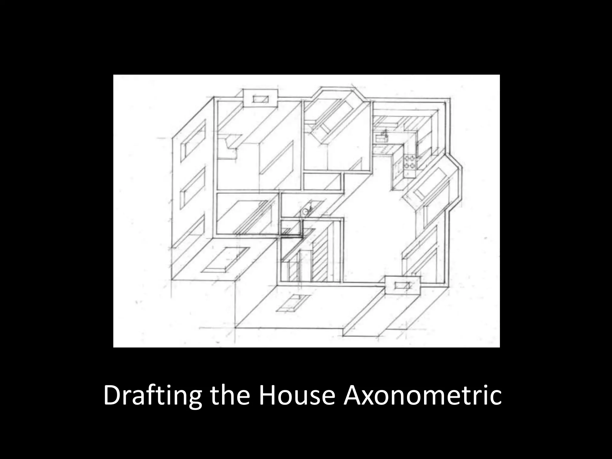
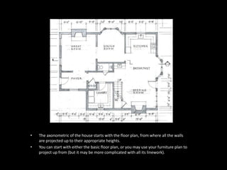
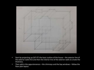
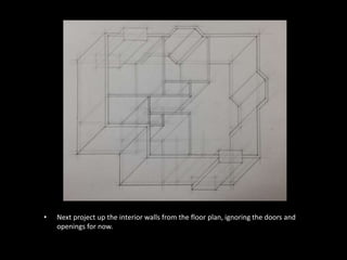
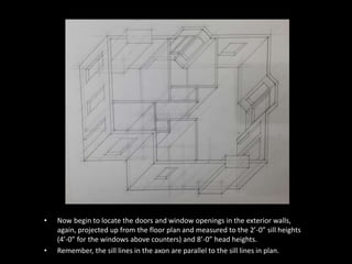
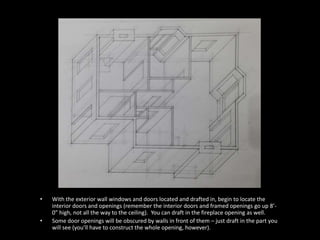
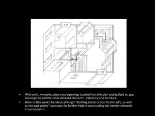
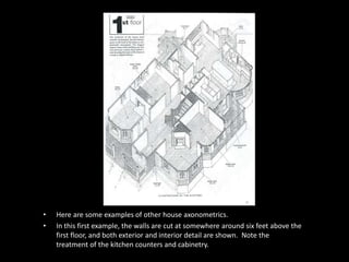
Drafting the House Axonometric
• The axonometric of the house starts with the floor plan, from where all the walls 
are projected up to their appropriate heights. 
• You can start with either the basic floor plan, or you may use your furniture plan to 
project up from (but it may be more complicated with all its linework).
• Start by projecting up (10’-0”) the basic outline of the house – the exterior line of 
the exterior walls first and then the interior line of the exterior walls to create the 
thickness. 
• Then add in the appurtenances – the chimneys and the bay windows – follow the 
floor plan layout.
• Next project up the interior walls from the floor plan, ignoring the doors and 
openings for now.
• Now begin to locate the doors and window openings in the exterior walls, 
again, projected up from the floor plan and measured to the 2’-0” sill heights 
(4’-0” for the windows above counters) and 8’-0” head heights. 
• Remember, the sill lines in the axon are parallel to the sill lines in plan.
• With the exterior wall windows and doors located and drafted in, begin to locate the 
interior doors and openings (remember the interior doors and framed openings go up 8’- 
0” high, not all the way to the ceiling). You can draft in the fireplace opening as well. 
• Some door openings will be obscured by walls in front of them – just draft in the part you 
will see (you’ll have to construct the whole opening, however).
• With walls, windows, doors and openings located from the plan and drafted in, you 
can begin to add the more detailed elements: cabinetry and furniture. 
• Refer to this week’s handouts (Ching’s “Building Construction Illustrated”), as well 
as the past weeks’ handouts, for further help in constructing the interior elements 
in axonometric.
• Here are some examples of other house axonometrics. 
• In this first example, the walls are cut at somewhere around six feet above the 
first floor, and both exterior and interior detail are shown. Note the 
treatment of the kitchen counters and cabinetry.
• In this image, the second floor is drawn directly onto the first floor, again showing 
exterior and interior detail. These are sequential axonometrics. 
• It is also drawn as a “phantom axonometric”, as the roof lines are indicated above, 
but you can see through them to make out the details of the second floor. Again, 
the cut line is about six feet above the second floor.
• In this example, the walls are again cut at somewhere around five feet high 
and both exterior and interior detail are shown. Note the inclusion of the 
North arrow (perfectly appropriate for axonometrics as well as plans).
• In this sequential axonometric view, like the last example, the next floor is 
built upon the first floor and the details of the exterior (including the roofs) 
are shown as well as the interior details. Again, we seem to be cut at around 
five feet above the second floor level.
• Here, we’ve risen to the third floor (attic floor) and most of the detail is the exterior 
of the house and it’s roof lines. 
• Phantom elements are introduced to indicate the complete roof line of the house, 
while allowing you to view the interior space of the attic floor. Again, for 
consistency, the floor plan is cut at about five feet high.
• Here is an example of a partial axonometric of a kitchen and dining space, with 
some of the walls drawn almost to their full height, while some other walls are only 
indicated as floor plan lines on the floor. 
• Phantom elements are also employed here (wall cabinets, refrigerator, blackboard) 
to indicate bulky elements that would otherwise interfere with the rest of the view.

Week 13 powerpoint drafting the house axonometric

  • 1.
    Drafting the HouseAxonometric
  • 2.
    • The axonometricof the house starts with the floor plan, from where all the walls are projected up to their appropriate heights. • You can start with either the basic floor plan, or you may use your furniture plan to project up from (but it may be more complicated with all its linework).
  • 3.
    • Start byprojecting up (10’-0”) the basic outline of the house – the exterior line of the exterior walls first and then the interior line of the exterior walls to create the thickness. • Then add in the appurtenances – the chimneys and the bay windows – follow the floor plan layout.
  • 4.
    • Next projectup the interior walls from the floor plan, ignoring the doors and openings for now.
  • 5.
    • Now beginto locate the doors and window openings in the exterior walls, again, projected up from the floor plan and measured to the 2’-0” sill heights (4’-0” for the windows above counters) and 8’-0” head heights. • Remember, the sill lines in the axon are parallel to the sill lines in plan.
  • 6.
    • With theexterior wall windows and doors located and drafted in, begin to locate the interior doors and openings (remember the interior doors and framed openings go up 8’- 0” high, not all the way to the ceiling). You can draft in the fireplace opening as well. • Some door openings will be obscured by walls in front of them – just draft in the part you will see (you’ll have to construct the whole opening, however).
  • 7.
    • With walls,windows, doors and openings located from the plan and drafted in, you can begin to add the more detailed elements: cabinetry and furniture. • Refer to this week’s handouts (Ching’s “Building Construction Illustrated”), as well as the past weeks’ handouts, for further help in constructing the interior elements in axonometric.
  • 8.
    • Here aresome examples of other house axonometrics. • In this first example, the walls are cut at somewhere around six feet above the first floor, and both exterior and interior detail are shown. Note the treatment of the kitchen counters and cabinetry.
  • 9.
    • In thisimage, the second floor is drawn directly onto the first floor, again showing exterior and interior detail. These are sequential axonometrics. • It is also drawn as a “phantom axonometric”, as the roof lines are indicated above, but you can see through them to make out the details of the second floor. Again, the cut line is about six feet above the second floor.
  • 10.
    • In thisexample, the walls are again cut at somewhere around five feet high and both exterior and interior detail are shown. Note the inclusion of the North arrow (perfectly appropriate for axonometrics as well as plans).
  • 11.
    • In thissequential axonometric view, like the last example, the next floor is built upon the first floor and the details of the exterior (including the roofs) are shown as well as the interior details. Again, we seem to be cut at around five feet above the second floor level.
  • 12.
    • Here, we’verisen to the third floor (attic floor) and most of the detail is the exterior of the house and it’s roof lines. • Phantom elements are introduced to indicate the complete roof line of the house, while allowing you to view the interior space of the attic floor. Again, for consistency, the floor plan is cut at about five feet high.
  • 13.
    • Here isan example of a partial axonometric of a kitchen and dining space, with some of the walls drawn almost to their full height, while some other walls are only indicated as floor plan lines on the floor. • Phantom elements are also employed here (wall cabinets, refrigerator, blackboard) to indicate bulky elements that would otherwise interfere with the rest of the view.