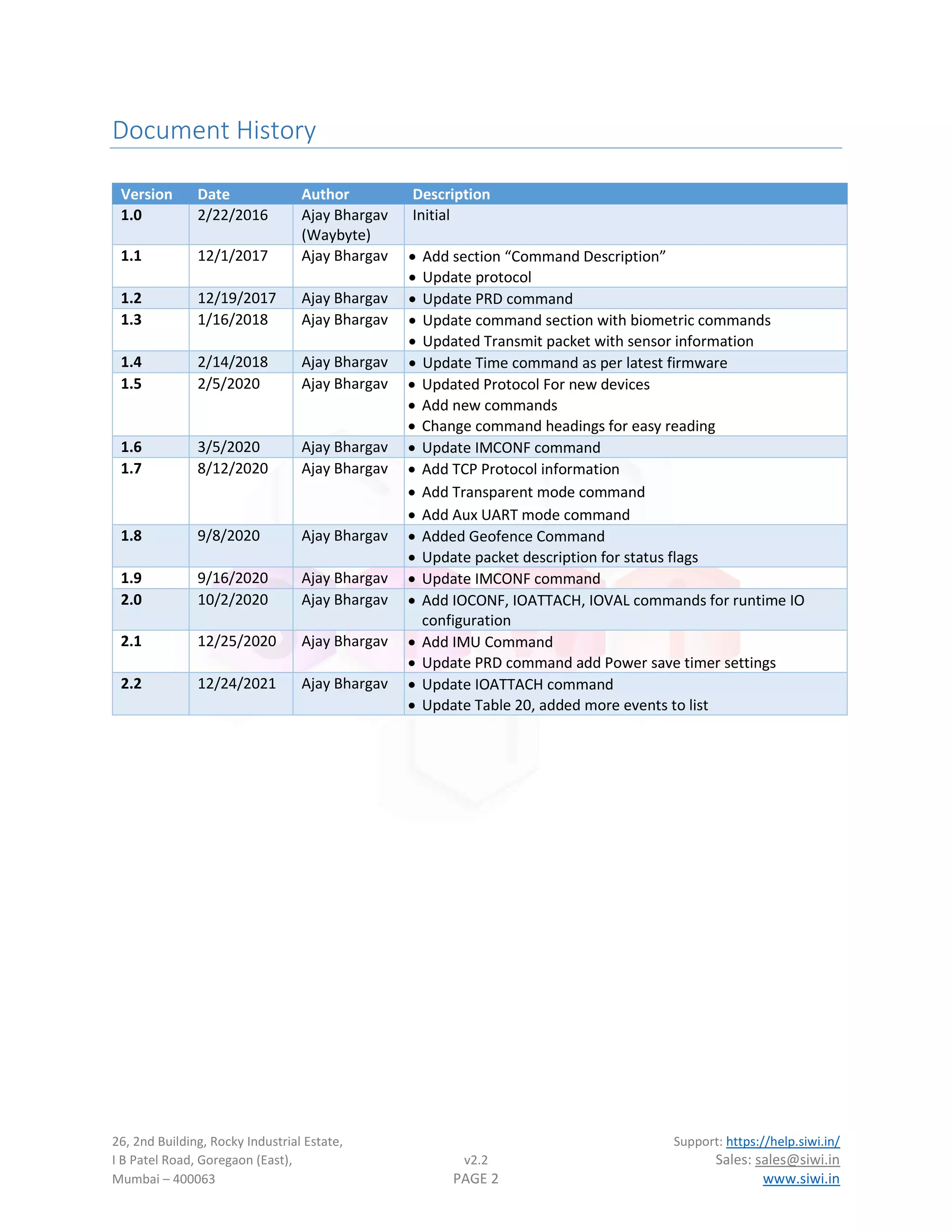
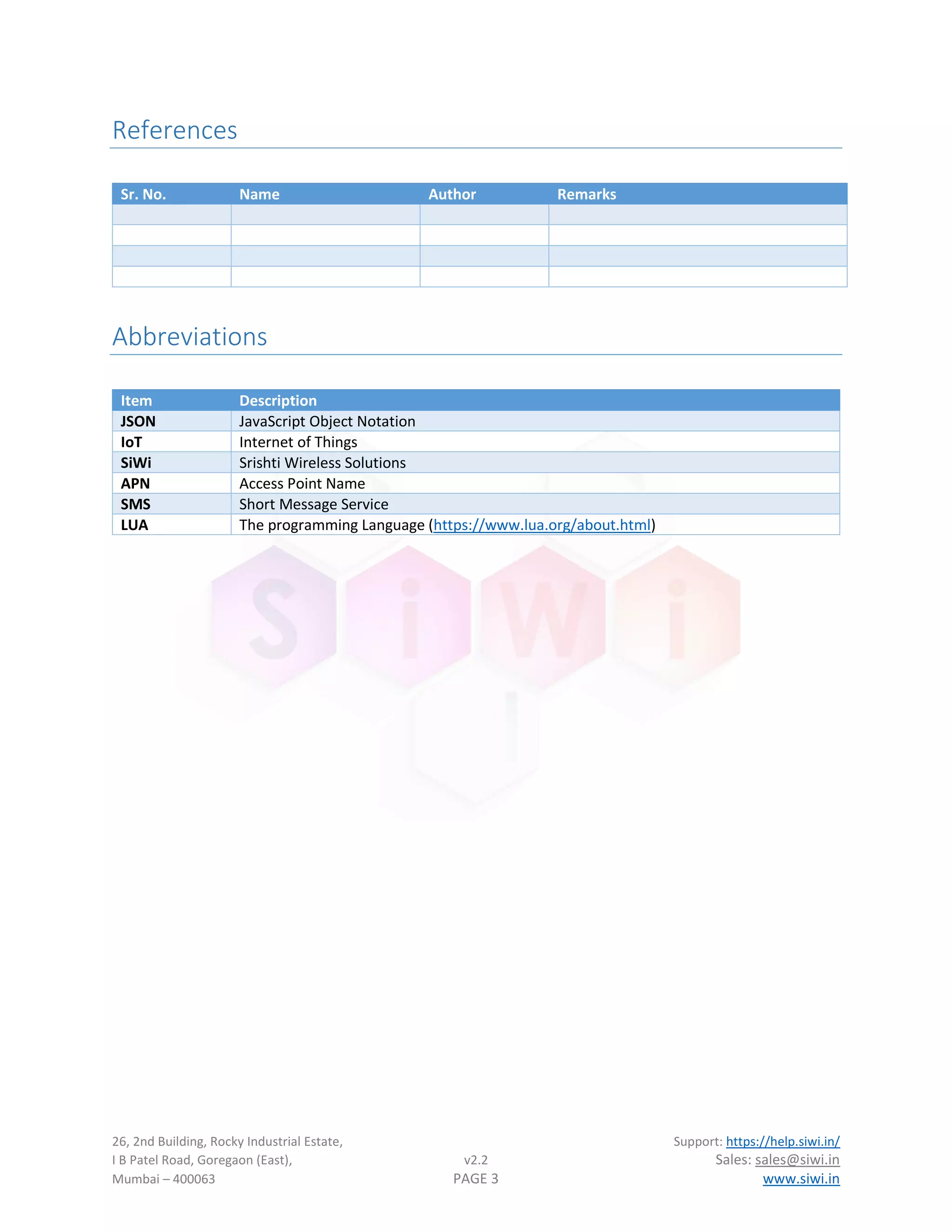
The document describes the JSON protocol for transmitting data from Srishti Wireless Solutions' Chukas+ and Scout+ vehicle tracking system (VTS) devices. It includes a sample JSON packet with fields for device ID, timestamp, location, I/O status, power levels, and debug information. Tables provide descriptions of each field in the packets. The protocol is designed to make it easy for web developers to integrate device data through JSON's common data format.


![26, 2nd Building, Rocky Industrial Estate, Support: https://help.siwi.in/
I B Patel Road, Goregaon (East), v2.2 Sales: sales@siwi.in
Mumbai – 400063 PAGE 9 www.siwi.in
JSON Transmit Protocol Description
Sample JSON Packet for Locator sent to server via HTTP/HTTPS POST method:
{
"uid": 222,
"info": {
"dt": 1512141732,
"txn": "E",
"msgkey": 0,
"msgid": 11720,
"cmdkey": ""
"cmdval": ""
},
"gps": {
"fix": "A",
"loc": [22.061200, 74.133017],
"speed": 0,
"sat": 10,
"alt": 14,
"dir": 137,
"odo": 1332893
},
"io": {
"box": 0,
"ign": 1,
"gpi": 1,
"status": 0,
"analog": [1935, 1234]
},
"pwr": {
"main": 1,
"batt": 1,
"volt": 3826,
"mvolt": 12.36,
},
"dbg": {
"status": [5, 5, 22, 8, 3, 1],
"ver": ["X.YY", "A.BB"],
"lib": "6.65"
}
}
NOTE: It is not possible to include all sample packets based on different sensor combinations, hence only
basic device packet is mentioned here. Please cross check the actual packet with field description table
provided below.](https://image.slidesharecdn.com/vtsprotocoldescriptionv2-220820134559-5e5da164/75/VTS-Protocol-description-v2-2-pdf-10-2048.jpg)
![26, 2nd Building, Rocky Industrial Estate, Support: https://help.siwi.in/
I B Patel Road, Goregaon (East), v2.2 Sales: sales@siwi.in
Mumbai – 400063 PAGE 10 www.siwi.in
Table 1: Transmit Protocol Field Descriptions
Key Data Type Description Value
uid Number Unit/Device ID (Software selectable, can be a numeric ID or
IMEI of device)
info Object Packet related info, Refer Table 2: Information Object
gps Object GPS related data, Refer Table 3: GPS Data Object
io Object Device’s Digital and Analog IO information, Refer
Table 4: Device IO Object
pwr Object Device power parameters, Refer Table 5: Power Status
Object
dbg Object Device debug parameters, Refer Table 6: Debug Status
Object
Table 2: Information Object
Key Data Type Description Value
dt Number Date time represented in Unix Timestamp format (Seconds
since 1 Jan, 1970)
1512141732
txn String Transmission Reason, A packet identifier. Refer Section
Packet Identification for list of packet Identifiers
"E"
msgkey Number This field provide information regarding key number during
key press event in the device, currently kept as reserved
0
msgid Number A numeric counter for data packet. 11720
cmdkey String Command key identifier “prd”
cmdval String This field contains value of the parameter when changed or
requested from server or SMS or command line interface
“60”
Table 3: GPS Data Object
Key Data Type Description Value
fix String GPS fix status
A – For Valid Data
V – For invalid data
“A”
loc Number
Array
Location represented as array of Number [Latitude,
Longitude]. Both Latitude and Longitude are represented as
decimal number up to a precision of 10 and a scale of 7.
[22.061200,
74.133017]
speed Number GPS speed parameter in Km/h 0
sat Number GPS Satellites in view 10
alt Number GPS altitude in meters 14
dir Number GPS direction/Bearing in degree 137
odo Number Device Odometer in meters 1332893](https://image.slidesharecdn.com/vtsprotocoldescriptionv2-220820134559-5e5da164/75/VTS-Protocol-description-v2-2-pdf-11-2048.jpg)
![26, 2nd Building, Rocky Industrial Estate, Support: https://help.siwi.in/
I B Patel Road, Goregaon (East), v2.2 Sales: sales@siwi.in
Mumbai – 400063 PAGE 11 www.siwi.in
Table 4: Device IO Object
Key Data Type Description Value
box Number Device enclosure open/close status
1 – Open
0 – Close
0
ign Number Vehicle ignition status
1 – Ignition On
0 – Ignition Off
1
gpi Number General purpose inputs represented in binary format
e.g., A value of 12 represents in binary as 0001100 which
means GPI0, GP1, GPI4, GPI5, GPI6 – Off
GP2, GP3 – On
0
status Number Status Flags: Bitwise status information see Table 11:
System Status Flags for more details.
0
analog Number
Array
Analog input value represented in millivolts [1234,1234]
fuel1
Object Fuel Data vary based on the fuel source selected
sensor2 Object
Array
Sensor data object. Refer
Table 9: Sensor Data object for more information
Table 5: Power Status Object
Key Data Type Description Value
main Number Power mains input availability status
1 – Mains Available
0 – Mains Unavailable
1
batt Number Battery connections status
1 – Battery Connected
0 – Battery Unconnected
1
volt Number Battery Voltage in millivolts 3826
mvolt Number Main battery input voltage in volts 12.36
Table 6: Debug Status Object
Key Data Type Description Value
status Number
Array
Debug array: [CREG, CGREG, CSQ, Net, Server, Offline]
CREG – GSM Registration status
CGREG – GPRS Registration Status
CSQ – Signal Quality
Net – Network debug field
Server – Server connectivity debug field (
Table 7: System's Server State)
Offline – Packet is online or offline indicator (1 – offline
packet/retransmitted, 0 – Online packet)
[5, 5, 22, 8, 3, 1]
1
Fuel key is not available in all protocols, devices with Fuel sensor installed will have this key present.
2
Sensor key is not available in all protocols, devices with temperature sensor installed will have this key present.](https://image.slidesharecdn.com/vtsprotocoldescriptionv2-220820134559-5e5da164/75/VTS-Protocol-description-v2-2-pdf-12-2048.jpg)
![26, 2nd Building, Rocky Industrial Estate, Support: https://help.siwi.in/
I B Patel Road, Goregaon (East), v2.2 Sales: sales@siwi.in
Mumbai – 400063 PAGE 12 www.siwi.in
ver String Array Device Application software version and hardware version [“1.9JCPLUS”,
“1.0”]
lib String Device firmware library version 6.65
Table 7: System's Server State
Index Description
0 Invalid or unknown state
1 No network registered
2 GSM network registered
3 GPRS & GSM network registered
4 Trying to connect to programmed server IP & Port
5 Connected to programmed server IP & Port
6 Currently sending data to server
Table 8: Fuel Sensor Data Object
Type Key Data
Type
Description Value
Analog/MODBUS/UART
Type Sensor
level Number Fuel Level in mV, to be calculated on server 1234
err Number Error code if sensor fails 0
Omnicomm Digital
Sensor
f Number Device sends all sensor parameter as it is to
server, please refer Omnicomm sensor
datasheet for more information.
t Number
n Number
err Number Error code if sensor reading fail
Ultrasonic Sensor
UFS-1/UFS-2
type String Device sends sensor information to server as
it is. Please read sensor datasheet for more
information
llv Number
rtv3
Number
temp4 Number
tilt4
Number
cvl4
sig Number
swc String
hwc String
err Number Error code if sensor reading fail
3
UFS-1 Type Sensor only
4
UFS-2 Type Sensor only](https://image.slidesharecdn.com/vtsprotocoldescriptionv2-220820134559-5e5da164/75/VTS-Protocol-description-v2-2-pdf-13-2048.jpg)
![26, 2nd Building, Rocky Industrial Estate, Support: https://help.siwi.in/
I B Patel Road, Goregaon (East), v2.2 Sales: sales@siwi.in
Mumbai – 400063 PAGE 16 www.siwi.in
Table 14: Sensor Error Bit Encoded
BIT7 BIT6 BIT5 BIT4 BIT3 BIT2 BIT1 BIT0
NA NA NA NA Sensor4 Sensor 3 Sensor2 Sensor1
NA - Fields in the table are not used and always read as 0.
BIT [0:4] – Each bit is assigned to a sensor. If corresponding bit is 1 that sensor is faulty or not responding.
E.g. If Sensor 3 and Sensor 1 are at fault the error value will can be computed as shown:
BIT7 BIT6 BIT5 BIT4 BIT3 BIT2 BIT1 BIT0 Error
0 0 0 0 0 1 0 1 5
Table 15: System Status Flags
BIT7 BIT6 BIT5 BIT4 BIT3 BIT2 BIT1 BIT0
NA NA NA NA Trip Status Geofence
Status
Immobilizer
Status
Box Status](https://image.slidesharecdn.com/vtsprotocoldescriptionv2-220820134559-5e5da164/75/VTS-Protocol-description-v2-2-pdf-17-2048.jpg)
![26, 2nd Building, Rocky Industrial Estate, Support: https://help.siwi.in/
I B Patel Road, Goregaon (East), v2.2 Sales: sales@siwi.in
Mumbai – 400063 PAGE 20 www.siwi.in
Transparent Mode for Auxiliary UART
VTS has auxiliary port for communication with external devices with firmware support available for many
different types of devices e.g., RFID, Fuel, UHF reader etc. However, there are some use case where user
need to get direct access of the device remotely. This is where transparent port comes into play.
In transparent mode, VTS device open a secondary TCP connection and sends its identification to the server
in format shown:
$TPUART,[Device UID],[Device IMEI]!
This helps server maintain individual connections based on device UID or IMEI.
Once connection is established, TCP connection works as a transparent channel between Auxiliary UART port
and server. Whatever is sent from server is directly transferred to UART and data from UART port is sent
directly to server.
Transparent mode can be helpful in managing external device as well as to debug external device in case of
failure.
To set UART into transparent mode user can send UMODE – Aux UART Operation Mode command.
Transparent mode parameters like server IP, server port and UART communication settings can be done
using TPCFG – Transparent mode configuration command.
External Device VTS Device
Cloud Server
UART
TCP Socket
Virtual Channel between cloud
server and external device](https://image.slidesharecdn.com/vtsprotocoldescriptionv2-220820134559-5e5da164/75/VTS-Protocol-description-v2-2-pdf-21-2048.jpg)
![26, 2nd Building, Rocky Industrial Estate, Support: https://help.siwi.in/
I B Patel Road, Goregaon (East), v2.2 Sales: sales@siwi.in
Mumbai – 400063 PAGE 21 www.siwi.in
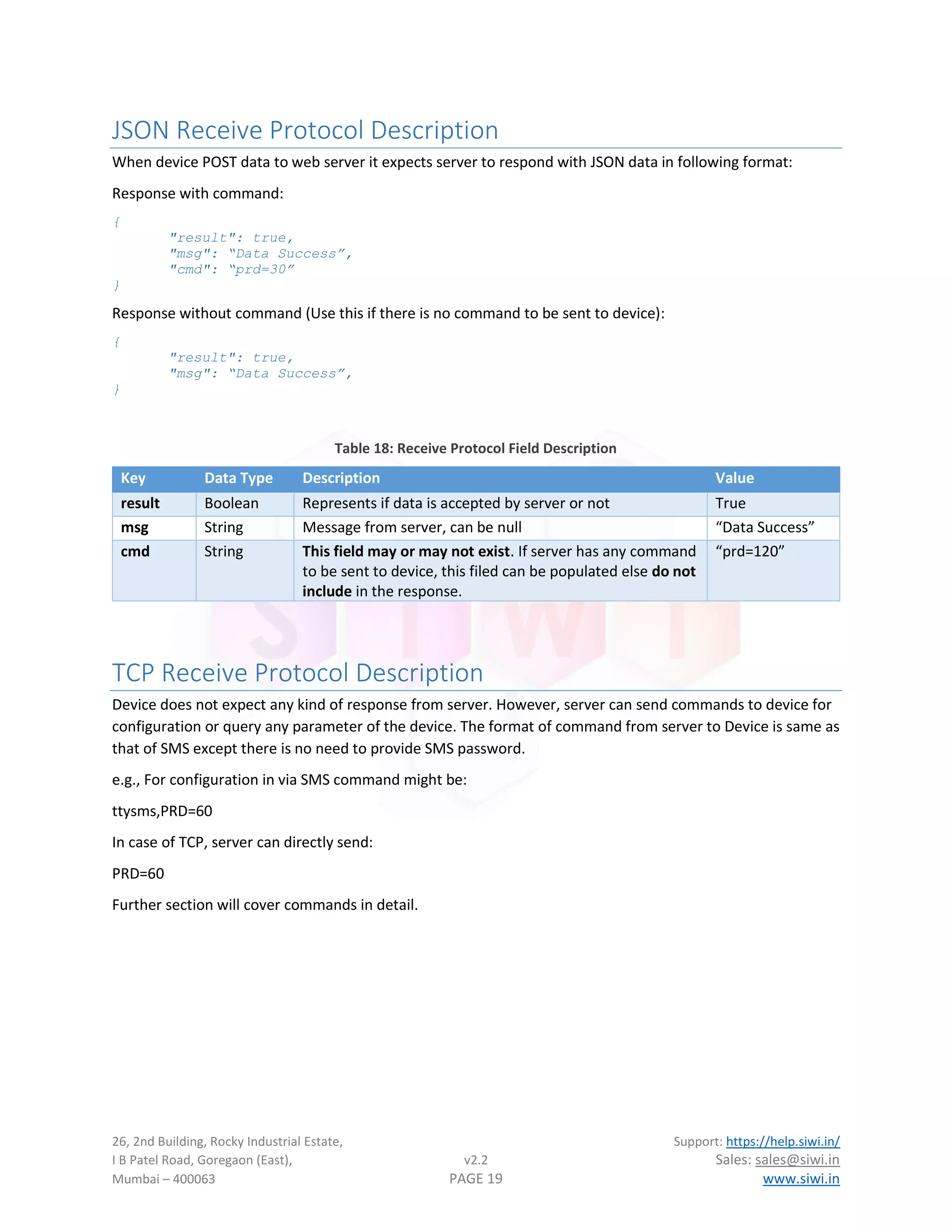
Command Description
Device supports configuration that can be done from either server or via SMS. Commands sent over SMS are
protected via SMS password. User can change this password anytime if they feel security is compromised in
anyway.
Commands sent from TCP are in simple format as shown:
cmd=parameters
Commands sent via SMS are sent with passwords as shown:
password,cmd=parameters
Default password is “ttysms”. So, if user has not changed any password then, commands can be sent as:
ttysms,cmd=parameters
SiWi Modbus device support two types of commands:
A. Configuration Commands: To configure device over the air using TCP/SMS. All configuration
commands require SMS password when sending over SMS.
B. Service Commands: Service level commands used during installation and troubleshooting. All
commands can be sent over SMS, and not all commands are allowed over TCP. The one which are
allowed will be mentioned separately.
Configuration Commands
1. TIME – Configure Clock
Set/get/sync system clock. VTS device can sync its clock from three different time sources, following is the list
based on source priority:
1. NSP – Network Service Provider (Lowest priority)
2. NTP – Network Time Protocol
3. GPS – GPS clock (highest priority)
Usage:
time - Get current operating mode and system date & time
time=[timestamp] - Set system time, where timestamp is Unix Timestamp/EPOC Time
time=auto – Set Auto synchronization mode with time sources
time=manual – Disable Auto mode, User can set time using timestamp
time=mode – Get Current operating mode (Auto/Manual)
time=server – Get current NTP server
time=server,[NTP Server address] – Set NTP server address, default is siwi.in
time=src – Get currently used time source.](https://image.slidesharecdn.com/vtsprotocoldescriptionv2-220820134559-5e5da164/75/VTS-Protocol-description-v2-2-pdf-22-2048.jpg)
![26, 2nd Building, Rocky Industrial Estate, Support: https://help.siwi.in/
I B Patel Road, Goregaon (East), v2.2 Sales: sales@siwi.in
Mumbai – 400063 PAGE 22 www.siwi.in
2. SMS – Admin Number Setting
Set SMS or call verification numbers. Currently only used for devices with call facility. SMS are currently
protected by SMS Password only.
Usage:
sms=<index>,[<value>]
Index – Index to read/write cell number (1-5)
value – Cell number to be stored, use value as “Delete” to remove stored number
3. NIP – Server IP/URL
Set server URL for posting JSON data or Server IP or domain for TCP data.
Usage for TCP:
nip=example.com
Usage for JSON:
nip=http://xxx.xxx.xxx.xxx/post.php
nip=http://www.example.com/post.php
if use is using a different port then use as shown
nip=http://www.example.com:port/post.php
4. NPT – Set Server Port
This command is used in case of TCP mode only and is used to set server port.
Usage:
npt=8446
5. PWD – Change SMS Password
Set Device SMS password
Usage:
pwd=<new>
new: New password
Note Default password is “ttysms”.
6. REBOOT – Device reboot
Reset or Reboot device
Usage:
reboot – No parameters needed
reboot=<delay>
Where delay is number of seconds to wait before reboot.
7. UNO – Protocol UID Configuration
Select to use Device ID (UID), IMEI or custom name (UNAME) of the device in UID filed of protocol.
Usage:
uno=[imei/uid/uname]](https://image.slidesharecdn.com/vtsprotocoldescriptionv2-220820134559-5e5da164/75/VTS-Protocol-description-v2-2-pdf-23-2048.jpg)
![26, 2nd Building, Rocky Industrial Estate, Support: https://help.siwi.in/
I B Patel Road, Goregaon (East), v2.2 Sales: sales@siwi.in
Mumbai – 400063 PAGE 23 www.siwi.in
8. UNAME – Device Custom Name
Set User defined name for device
Usage:
uname=<value> - where value is new device name in alphanumeric format (50 characters max)
9. OFR – Clear Offline Data
Clean and reset offline data
Usage:
ofr – Get currently stored offline packet count
ofr=1 – Clear Offline storage
10.DNSCFG – DNS Server Configuration
Configure custom DNS servers. By default, device will use DNS server provided by GSM service provider.
Usage:
dnscfg=primary,secondary
dnscfg=reset – Reset DNS server to default (reboot required)
e.g.
dnscfg=8.8.8.8,8.8.4.4
11.TZN5
- Timezone Configuration
Device Time zone setup
Usage:
tzn=<+/-HH:MM>
12.APN – Access Point Configuration
Set APN information for internet access
Usage:
apn=apn_name,[apn_username],[apn_password]
apn_name: Access point name. Can be set to "auto" for auto APN feature.
apn_username: APN username (Optional)
apn_password: APN user password (Optional)
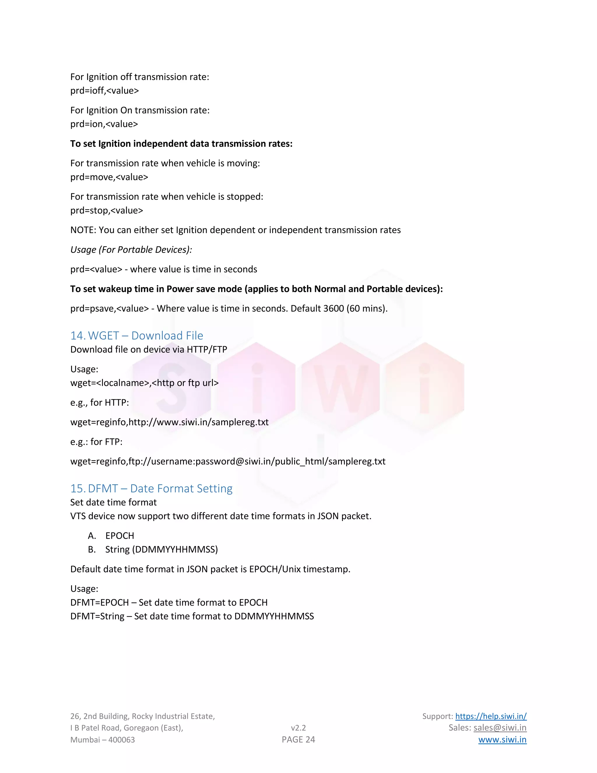
13.PRD – Data Period Configuration
Set data transmission period/rate
Usage (For Non-Portable Devices):
To set all timings at once:
prd=<value> - where value is time in seconds
To set ignition dependent data transmission rate.
5
TZN will not affect UNIX timestamp since they are always represented in GMT.](https://image.slidesharecdn.com/vtsprotocoldescriptionv2-220820134559-5e5da164/75/VTS-Protocol-description-v2-2-pdf-24-2048.jpg)
![26, 2nd Building, Rocky Industrial Estate, Support: https://help.siwi.in/
I B Patel Road, Goregaon (East), v2.2 Sales: sales@siwi.in
Mumbai – 400063 PAGE 25 www.siwi.in
16.ODM – Initial Odometer configuration
Set initial odometer value. It is sometimes necessary to set a start value of odometer during new installation
if user do not want odometer to start from 0. This command sets the initial value of odometer.
Usage:
odm=<value>
Value of odometer is in meters, e.g. if user wants to set 1950Km as initial value then command should be
odm=1950000
17.ESS – Speed limit Setting
Set excess speed value or maximum speed limit of vehicle. After the maximum speed limit of vehicle is set
server will be notified if device moves at a higher speed than set value. If buzzer is installed in the device,
then buzzer will also beep locally to notify driver of speed limit reached.
Usage:
ess=<value>
Value is in Km/h
18.STARTV/STOPV – Immobilizer Commands
These are immobilizer commands and only available in device with immobilizer feature. These commands do
not have any special parameters.
Startv – Start the vehicle
Stopv – Stop the vehicle
19.HBRK – Harsh Break Threshold
Set harsh break threshold in g (1g = 9.8m/s2
). Default value is 0.55g
Usage:
hbrk=<value>
20.HACC – Harsh Acceleration Threshold
Set harsh acceleration threshold in g (1g = 9.8m/s2
). Default value is 0.43g
Usage:
hacc=<value>
21.EVSET – Event Configuration
To enable or disable event packets.
Usage:
evset=<list of txn to disable>,[0/1]
TXN list can be found in Table 17: Event Packet Identifier
22.SOS – SOS Acknowledge
Server command to acknowledge SOS packet. This will provide LED indication to person in vehicle that server
has acknowledged SOS event sent by device. This command has no parameters.](https://image.slidesharecdn.com/vtsprotocoldescriptionv2-220820134559-5e5da164/75/VTS-Protocol-description-v2-2-pdf-26-2048.jpg)
![26, 2nd Building, Rocky Industrial Estate, Support: https://help.siwi.in/
I B Patel Road, Goregaon (East), v2.2 Sales: sales@siwi.in
Mumbai – 400063 PAGE 26 www.siwi.in
23.TEMPTH6
- Temperature Alert Setting
Set temperature threshold.
Usage:
tempth=<id>,<high value>,<low value>
Where high and low value are the temperature thresholds in ˚C
24.RHTH – Humidity Alert Setting
This command is used to set humidity sensor thresholds in percent. Default values are 5% for low and 80%
for high.
Usage:
RHTH=<ID>,<HIGH>,<LOW>
Where ID is sensor ID.
High and low are relative humidity thresholds in percent.
25.SENSOR – View/Set sensor information
This command is used to view real time sensor values and set per sensor offsets. For temperature sensor it is
also used to reset the sensor if needed during installation.
Usage:
To Reset Temperature sensor
SENSOR=[ID],reset
To View current offset values:
SENSOR=[ID],offset
To Configure Temperature sensor offset
SENSOR=[ID],[Temp_offset]
To Configure Temperature and Humidity sensor offsets
SENSOR=[ID],[Temp_offset],[Humid_offset]
ID is sensor ID starting from 1.
To Set Temperature sensor count installed on device:
SENSOR=temp,<count>
To Set Temperature & Humidity sensor count installed on device:
SENSOR=trh,<count>
Temperature and Humidity offset values are in float can be negative or positive.
NOTE: Please be careful when resetting the sensor. Only use it when really required. Contact support team
for any help.
6
This command is only available in devices with temperature sensors installed.](https://image.slidesharecdn.com/vtsprotocoldescriptionv2-220820134559-5e5da164/75/VTS-Protocol-description-v2-2-pdf-27-2048.jpg)
![26, 2nd Building, Rocky Industrial Estate, Support: https://help.siwi.in/
I B Patel Road, Goregaon (East), v2.2 Sales: sales@siwi.in
Mumbai – 400063 PAGE 27 www.siwi.in
26.BUZZ7
- Buzzer Control
To turn buzzer on or off from server
Usage:
buzz=<duration>
Duration is provided in seconds, to turn off duration set as 0.
Buzz=<type>,<on/off>
Type can be:
SL: Speed Alert
TMP: Temperature Alert
EMR: SOS Alert
TA: Tilt Alert8
27.BTYPE9
- Buzzer Configuration
Set or select buzzer type
Usage:
btype=<1/0>
1 – For Hooter type
0 – For Beeper type
28.RFCONF10
- RFID Reader Setting
To set RFID reader configuration
Usage:
rfconf=[timeout],[mode]
Timeout is in seconds for repeat card detection, set to 0 to disable and only alternate cards will be detected.
mode – Card display format, “decimal” (default) or “hex”.
29.BIOCONF11
- Biometric Reader Setting
To set Biometric/Fingerprint reader configuration
Usage:
bioconf=[operation],[argument]
Supported Operations:
Load: To load biometric template from URL
bioconf=load,[index],[URL]
where index can be 1 to 200 (biometric ID)
7
This command is only available in devices with buzzer installed.
8
Only available if MEMS sensor installed
9
This command is only available in devices with buzzer installed.
10
This command is only available in devices with RFID installed.
11
This command is only available in devices with Biometric installed.](https://image.slidesharecdn.com/vtsprotocoldescriptionv2-220820134559-5e5da164/75/VTS-Protocol-description-v2-2-pdf-28-2048.jpg)
![26, 2nd Building, Rocky Industrial Estate, Support: https://help.siwi.in/
I B Patel Road, Goregaon (East), v2.2 Sales: sales@siwi.in
Mumbai – 400063 PAGE 28 www.siwi.in
Del: To delete template
Bioconf=del,[index]
Where index can be 1 to 200. To delete all templates at once use:
Bioconf=del,all
30.IBCONF12
–iButton Reader Setting
This command is used for configuring iButton reader operation
Usage:
IBCONF=[Timeout],[Mode]
Timeout is in seconds for repeat iButton detection. Setting this value to 0 disable same ID detection back to
back. Default value is 2 sec.
Mode can be sent to 0 or 1, 0 as Normal mode and 1 as reverse mode. In reverse mode ID is sent to server in
reverse order.
31.IMCONF – Immobilizer Configuration
This command is used to configure advanced configuration for immobilizer. To automate immobilizer control
based on RFID/Biometric/iButton. The individual configuration of control devices can be done with
RFCONF/BIOCONF/IBCONF –iButton commands respectively.
Command Format:
IMCONF=<Operation>,<Type>,<arguments…>
Operation can be “set” or “get to set or get the configuration value respectively.
Type defines the configuration on which operation to be performed and based on type the argument list is
decided. Following are the types:
CTL: Control Configuration
This configuration is used to set the source of control for Immobilizer. The source can be as follows:
0 – No Source (Default)
1 – Any scanned ID from RFID/Biometric/iButton reader (No validation)
2 – RFID Reader
3 – Biometric Reader
4 – iButton Reader
Usage:
IMCONF=<set/get>,CTL,<source>,[<mode>]
Mode is optional argument and can be any of the following. The operation mode is only valid when source is
not set to 0 (No Source).
Normal: This is default mode of operation. In this mode immobilizer is disabled when a valid ID is found or
STARTV command is sent to the device. Immobilizer is enabled again after ignition is turned off.
12
This command is only available in device with iButton Reader installed.](https://image.slidesharecdn.com/vtsprotocoldescriptionv2-220820134559-5e5da164/75/VTS-Protocol-description-v2-2-pdf-29-2048.jpg)
![26, 2nd Building, Rocky Industrial Estate, Support: https://help.siwi.in/
I B Patel Road, Goregaon (East), v2.2 Sales: sales@siwi.in
Mumbai – 400063 PAGE 30 www.siwi.in
34.HEADER – HTTP Header Configuration
Set custom HTTP Header during data post. Used in case of JSON only.
User can add custom headers to be added to HTTP POST request sent by device to server. Most of the time
custom headers are needed for device authentication or security. Header is set in a key: value pair in the
POST request.
Usage:
To set key and value together:
HEADER=set,<keyname>,<keyvalue>
e.g. HEADER=set,Authorization,c29tZSB2YWx1ZSBhcyBhdXRoIGtleQ==
The above will add following to the POST Header
Authorization: c29tZSB2YWx1ZSBhcyBhdXRoIGtleQ==
To change only Key Name:
HEADER=key,<keyname>
To change only Key value:
HEADER=value,<keyvalue>
To delete key, value:
HEADER=del or HEADER=delete
35.FCFG – Fuel Sensor configuration
This command is used to configure fuel sensors supported by device.
Usage:
FCFG=[Operation],[Value…]
The operation is the sub-command to run for fuel configuration. Based on operation value and parameter
count can be different. Operations are explained below
SRC: Sensor Type
Device supports 5 different types of sensors which are pre implemented in the firmware.
FCFG=SRC,<type>
Type is as follows:
1 – Analog Sensor
2 – Modbus type Sensor
3 – UART type sensor
4 – Omnicomm Digital sensor
5 – Ultrasonic Fuel sensor
PORT: Serial port configuration
Sensors which connects over serial/modbus require port parameters to be configured.
FCFG=PORT,[Baud],[Com parameters]
Baud is Baudrate of com port. Default is 9600](https://image.slidesharecdn.com/vtsprotocoldescriptionv2-220820134559-5e5da164/75/VTS-Protocol-description-v2-2-pdf-31-2048.jpg)
![26, 2nd Building, Rocky Industrial Estate, Support: https://help.siwi.in/
I B Patel Road, Goregaon (East), v2.2 Sales: sales@siwi.in
Mumbai – 400063 PAGE 31 www.siwi.in
Com parameters are serial port communication parameters like databits, parity, stopbits etc. The parameters
are given in following format.
[Databits][Parity][Stopbits]
Databits: 7 or 8
Parity: n – None, e – Even, o – Odd, m – Mark, s – Space
Stopbits: 1 or 2
Default value is 8n1 for 8 bits, no parity and 1 stopbit.
SID: Slave ID
For omnicomm and modbus devices, slave id is required. Default value is 99.
FCFG=SID,<ID>
OFF: To set sensor offset value
FCFG=OFF,<value>
Value is the offset to sensor reading can be positive or negative. Default 0.
CTL: Fuel data post process control
To smooth out any data abnormalities caused by vehicle motion etc., the data is post-processed inside the
device before it is sent to server. This setting enables or disable post processing of sensor data. Default is off.
FCFG=CTL,<0/1>
0 – Off, 1 – On
FIL: Post process level
This operation controls the level of post processing done on data. Higher the value, slower will be the
response to change in data. Default level is 2.
FCFG=FIL,<level>
Level can be anywhere from 0 to 10.
RESET: Reset Settings
This operation will reset fuel sensor settings stored on device to default.
36.UMODE – Aux UART Operation Mode
This command is used to configure operation mode of Auxiliary UART port. Default mode is application
mode.
Usage:
UMODE=<mode>
Mode can be 0 for Application mode (default), 1 for transparent mode.
For detail on transparent mode see Transparent Mode for Auxiliary UART.](https://image.slidesharecdn.com/vtsprotocoldescriptionv2-220820134559-5e5da164/75/VTS-Protocol-description-v2-2-pdf-32-2048.jpg)
![26, 2nd Building, Rocky Industrial Estate, Support: https://help.siwi.in/
I B Patel Road, Goregaon (East), v2.2 Sales: sales@siwi.in
Mumbai – 400063 PAGE 32 www.siwi.in
37.TPCFG – Transparent mode configuration
This command is used to configure transparent mode settings.
Usage:
TPCFG=<operation>,<value,…>
Operation are sub commands explained further in this section and Value list is optional and depends on
operation being executed. When value is not present device will return current settings.
CONN – Set Transparent server configuration
TPCFG=CONN,[IP],[PORT]
PORT – Set UART port configuration
TPCFG=PORT,[BAUD],[Com parameters],[DIRCTL]
BAUD: is Baudrate of UART port, Default Baudrate is 9600
Com Parameters: UART communication parameters same as: PORT: Serial port configuration
default value is 8n1.
DIRCTL: This parameter is optional to enable direction control if external device is using RS485 port.
38.GEO – Configure geofence
Device support only one geofence which can be either a circle or a rectangle.
Usage:
GEO=<event type>,<fence type>,<fence parameters>
Event Type:
0: Fence disabled, when fence is disabled all other parameters are ignored.
1: Fence Enabled and Event generated on geofence entry.
2: Fence Enabled and Event generated on geofence exit.
3: Fence Enabled and Event generated on geofence entry and exit.
Fence Type:
0: Fence type circular
1: Fence type rectangular
Fence Parameters: based on fence type fence parameter vary
For Circular Geofence
GEO=<event type>,0,<latitude>,<longitude>,<radius>,<name>
Latitude: Latitude of center of circular geofence
Longitude: Longitude of center of circular geofence
Radius: Fence radius in meters, this parameter is optional. Minimum and default value is 100m.
Name: User defined name for geofence, this can be any alphanumeric value not more than 31 characters.
For Rectangular Geofence:
GEO=<event type>,1,<latitude 1>,<longitude 1>,<latitude 2>,<longitude 2>,name
Latitude 1: Latitude of top left corner of geofence
Longitude 1: Longitude of top left corner of geofence
Latitude 2: Latitude of bottom right corner of geofence](https://image.slidesharecdn.com/vtsprotocoldescriptionv2-220820134559-5e5da164/75/VTS-Protocol-description-v2-2-pdf-33-2048.jpg)

![26, 2nd Building, Rocky Industrial Estate, Support: https://help.siwi.in/
I B Patel Road, Goregaon (East), v2.2 Sales: sales@siwi.in
Mumbai – 400063 PAGE 36 www.siwi.in
Usage:
IOATTACH=<ioname>,2, <function>
Dual Mode Configuration
In this mode IO line can be attached to two events, one event set the line active high, and another sets it
active low.
Usage:
IOATTACH=<ioname>,3, <function1>,<function2>
Function 1: Active high event
Function 2: Active low event
Function code as same as described in Table 20.
41.IOVAL – Set or get current level of GPIO lines
This command is only valid for GPIO lines only.
Usage:
IOVAL=<ioname>[,val]
Ioname is same as described in Table 19: IO Name and Specifications
Val is optional when setting level of output line. 1 means active high and 0 means active low level. The output
state is decided by active state of the IO line configured using IOCONF – Configure Input/Output Pins
command.
Usage for Pulse output:
IOVAL=<ioname>,pulse,<count>,<high_time>,<low_time>
Count: Number of pulses to generate
high_time, low_time: Pulse high and low duration respectively in milliseconds.
42.IMU – Configure IMU settings
This command is used to configure and calibrate Inertial Measurement Unit.
Usage:
IMU=<op>,<param>
Op: Operation or configuration to change.
Param: Value based on operation
TILT
Set tilt angle for event generation when vehicle is tilted
Usage:
IMU=TILT,<value>
Where value is angle in degrees. Default value is 45°
MTH
Set motion detection threshold.
Usage:
IMU=MTH,<value>
where value is time in seconds. Default value is 10s.](https://image.slidesharecdn.com/vtsprotocoldescriptionv2-220820134559-5e5da164/75/VTS-Protocol-description-v2-2-pdf-37-2048.jpg)