vPC allows links connected to two Nexus switches to appear as a single port channel to a third device. It provides advantages like eliminating STP blocked ports, using all available uplink bandwidth, and fast convergence upon failures. Configuring vPC involves the vPC peer switches, peer link, domain, and member ports. vPC avoids loops at the data plane layer. It can be used within a single data center for active-active server connectivity or between two data centers to extend VLANs across sites at layer 2. Object tracking allows vPC to modify its state based on peer link states.


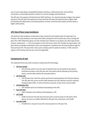

![Deployment Scenarios
vPC is typically used at the access or aggregation layer of the data center. At access layer, it is used for
active/active connectivity from network endpoint (server, switch, NAS storage device.) to vPC domain.
At aggregation layer, it is used for both active/active connectivity from network endpoint to vPC domain
and active/active default gateway for L2/L3 boundary.
However, because vPC provides capabilites to build a loop free topology, it is also commonly used to
interconnect two separate data centers together at layer 2, allowing extension of VLAN across the 2
sites.
The 2 common deployment scenarios using vPC technology are listed as below:
Inside Data Center:
Single-sided vPC (access layer or aggregation layer) - In single-sided vPC, access devices are
directly dual-attached to pair of Cisco Nexus 7k or 5k Series Switches forming the vPC domain.
The access device can be any endpoint equipement (L2 switch, rack-mount server, blade server,
firewall, load balancer, network attached storage [NAS] device). Only prerequisite for the access
device is to support portchanneling (or link aggregation) technology.
Double-sided vPC (access layer using vPC interconnected to aggregation layer using vPC) -This
topology superposes two layers of vPC domain and the bundle between vPC domain 1 and vPC
domain 2 is by itself a vPC. vPC domain at the bottom is used for active/active connectivity from](https://image.slidesharecdn.com/3778fed0-9a8b-423a-b659-144f61fe48d9-160330034303/85/vPC_Final-6-320.jpg)