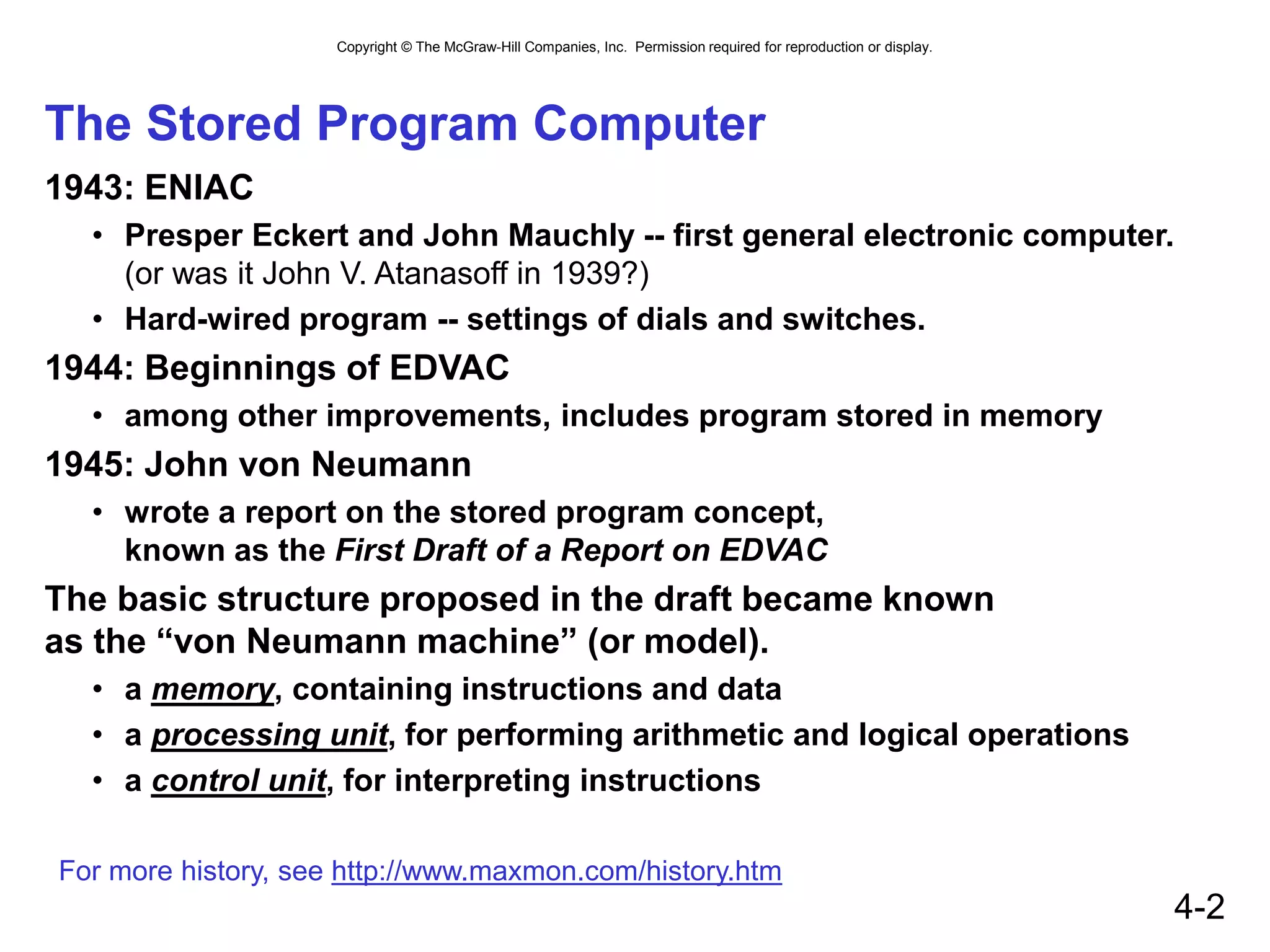
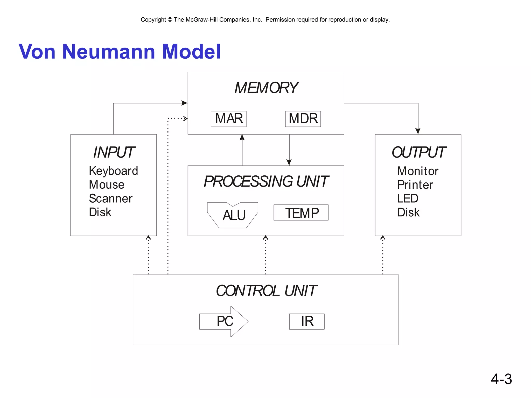
The document describes the Von Neumann model of computer architecture. It details the key components of a computer system based on this model, including the memory, processing unit, control unit, and input/output. The processing unit contains an arithmetic logic unit and registers. The control unit fetches and interprets instructions to direct operation. Instructions are stored in memory along with data. The document provides examples of instructions for the LC-3 architecture to illustrate how they are encoded and processed.
![Copyright © The McGraw-Hill Companies, Inc. Permission required for reproduction or display.
4-11
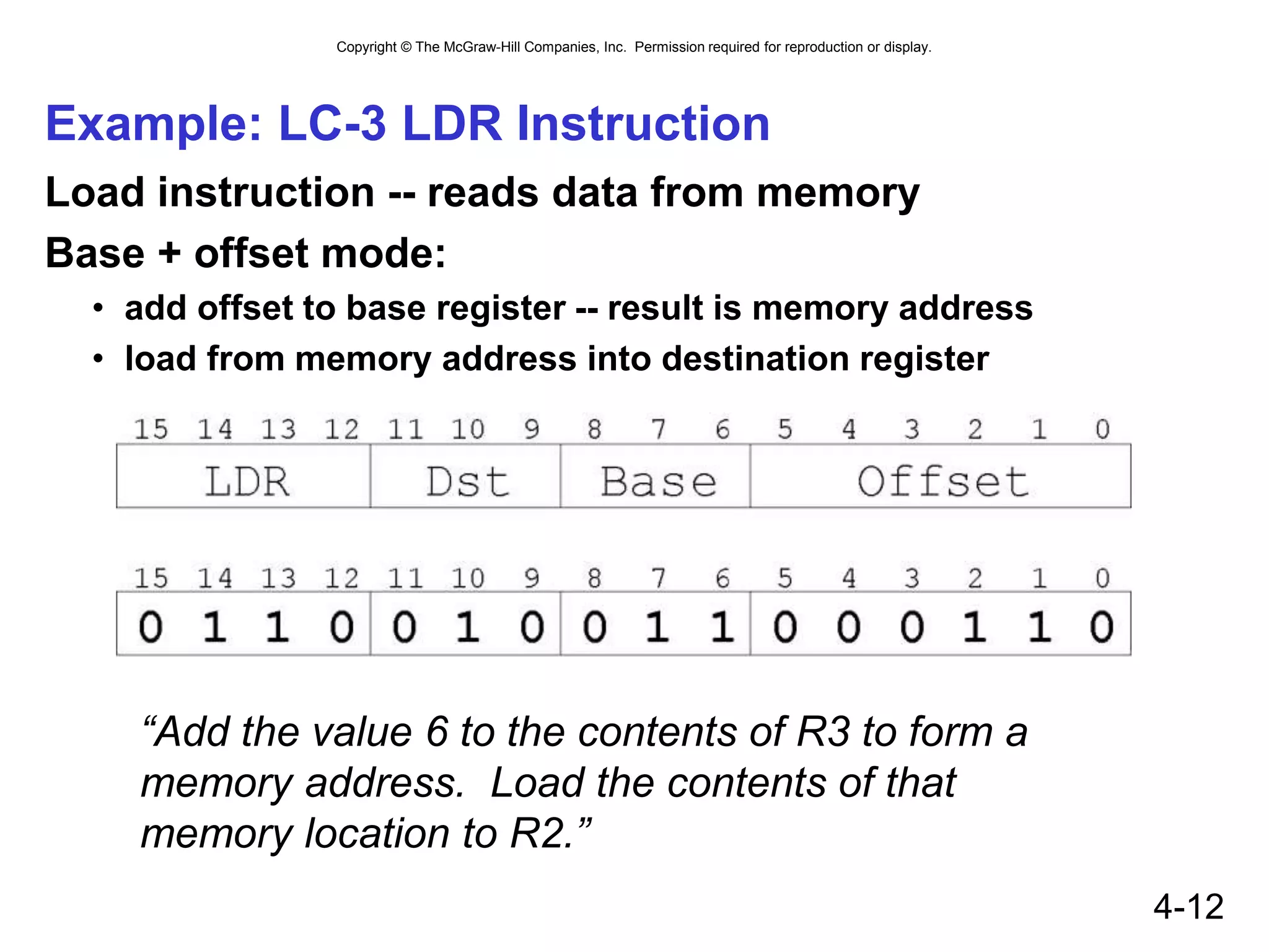
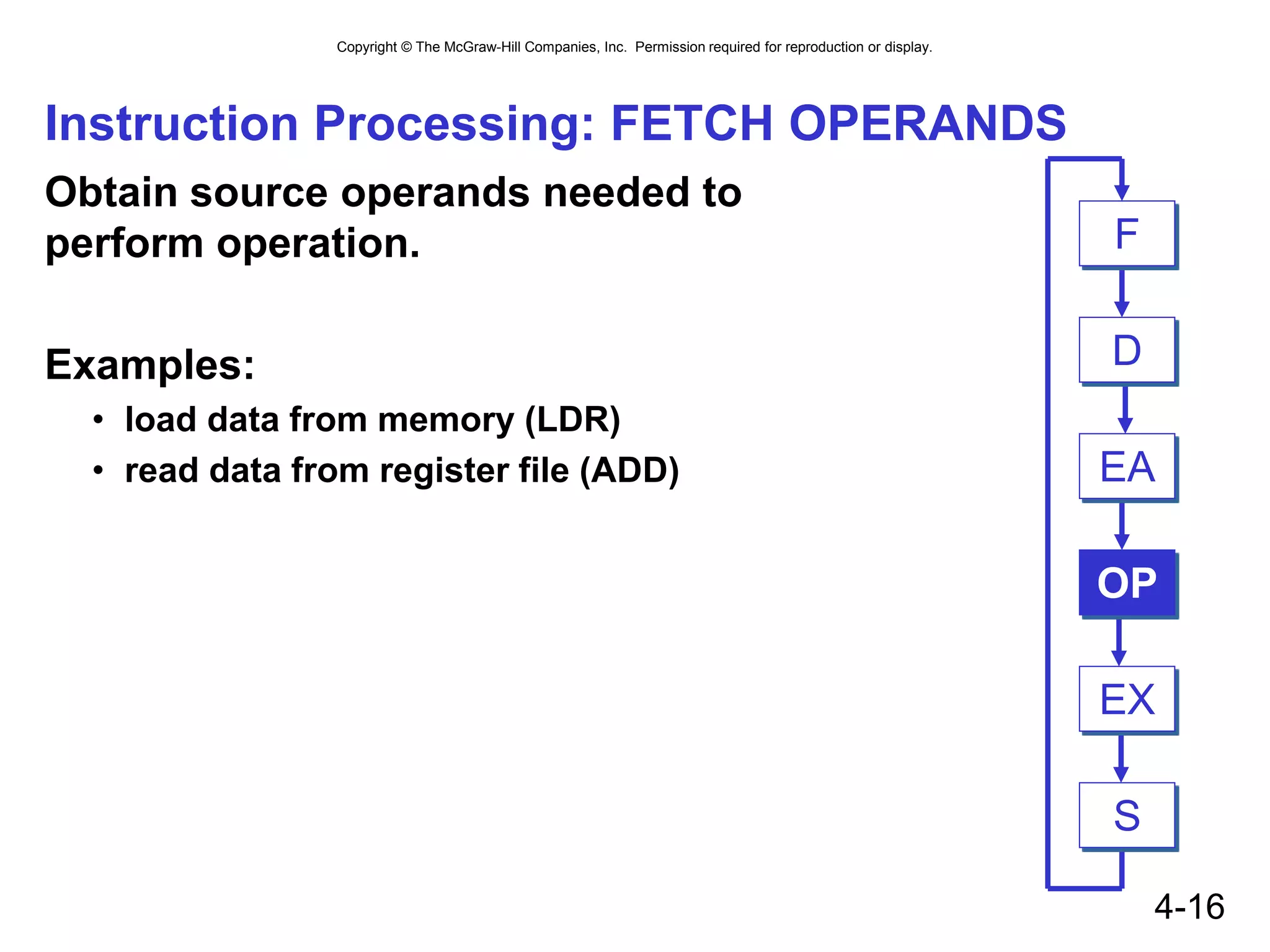
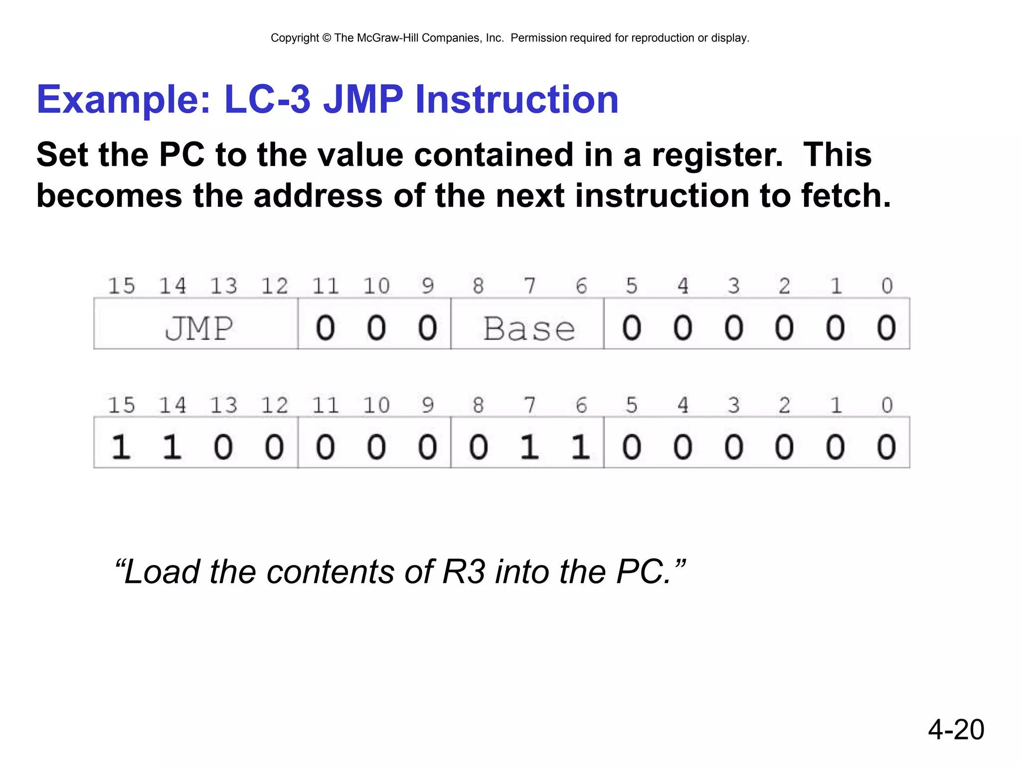
Example: LC-3 ADD Instruction
LC-3 has 16-bit instructions.
• Each instruction has a four-bit opcode, bits [15:12].
LC-3 has eight registers (R0-R7) for temporary storage.
• Sources and destination of ADD are registers.
“Add the contents of R2 to the contents of R6,
and store the result in R6.”](https://image.slidesharecdn.com/pattpatelch04-221029032926-6544eb8b/75/Von-neuman-architecture-11-2048.jpg)