Vapour pressure-model-1354 atac
•
0 likes•204 views

The Hallikainen Model 1354 Vapour Pressure Analyser is a completely automated process stream analyser. Its fast response and minimal maintenance requirements put the 1354 at the forefront of your vapour pressure measurement needs.
![SPECIFICATIONS
Analyser performance Accurate measurements can be made from samples having viscosities up to 80cP
Available ranges From 0-1.6 barA standard (other spans and other units of measurement available)
Repeatability ±0.007 bar (0.1 psi)
Precision Within ASTM D323 (ASTM D1267 for LPG)
Response time Better than 50 seconds
Output signal Range: 4-20mA fully isolated loop powered and/or digital output depending on selected transmitter
Out-of-service alarm contact signalling mains failure (or off) or bath temperature fuse blown.
2 sets c/o contacts rated at 25A @ 250V or 12A @ 120V
Sample pressure (g) Depends on the back pressure at the analyser outlet but must normally exceed [outlet pressure (bar) x 2.5]
+7 bar. Standard max pressure 60 bar (870 psi)
Sample temperature Should remain within the range 25°C-50°C (77°F-120°F). Fluctuations must be minimal and not exceed
5°C (9°F).
Sample flow 55-230 litres/hour (12-50 gallons/hour) depending on back pressure
Sample conditioning Complete sample systems can be supplied to pre-condition process sample to the conditions required at the
analyser inlet.
Sample disposal Return to process or a recovery system. Sample recovery systems can be supplied.
Power supply Voltage 115V or 230V ±10% single phase. Frequency 50 or 60Hz. Consumption 2.0 kVA
Cooling water A supply of potable water at up to 135 l/h (30gal/h) and at a temperature ≤30°C (maximum pressure 7 barg)
should be provided to carry away excess heat. The necessary coil is fitted as standard. If potable water is not
available alternative cooling coil materials can be provided.
Oil for temperature bath 11 litres (2.5 gal) of Shell Thermia B or equivalent. Reid vapour pressure tests are carried out at 37.8°C (100°F),
but with this analyser, temperatures up to 110°C (240°F) may be selected and controlled to ±0.1°C.
Local display Gauge indicates absolute vapour pressure. 0-100% linear scale on the transmitter
Standard connections Sample inlet : ⅜” NPT(male) Sample outlet : ⅜” NPT (male)
Cooling water : ¼” NPT (female) IN Cooling water : ¼” NPT (female) OUT
Electrical ISO M20 Standard (½” NPT NEC)
Signal out : As transmitter specification, either EExd or EExia with 4-20mA isolated output
and / or digital output.
Explosion protection
options
This analyser is ATEX certified for use in Zone 1 hazardous areas
II 2G EEx d e ia IIB T4 Certificate no. ITS 09ATEX16356X
Option: II 2G EEx d e ia IIB + H2 T4 Certificate no. ITS 09ATEX16357X
Environmental
protection
Will operate satisfactorily under normal ambient temperature conditions between 0 and 55°C (32-130°F) but
should be sheltered from direct sun and rain - see options below.
Frost protection is recommended for water cooled analysers.
Dimensions Width: 500mm Length: 900mm Height: 1400mm Weight: 180kg *Allow Extra for Access
Mounting Floor fixing bolt holes (4 off 5
/8
” dia) at 448mm (175
/8
”) x 351mm (1313
/16
”) centres
Options • Configuration for CSA local approval
• Cooling coil in Hastelloy C or Monel
• Digital bath temperature transmitter and/or indicator instead of mercury thermometer
• Choice of pressure transmitter to include HART, Foundation Fieldbus or Modbus communications.
(Remote diagnostics from DCS or hand held communicator)
• Environmental protection to IP65
• ATEX IIB + H2
certification
Analytical Technology & Control Limited
Broadway, Market Lavington SN10 5RQ, UK
T +44 (0) 1380 818411
F +44 (0) 1380 812733
E sales@atacgroup.com
W www.atacgroup.com
An Advanced Company
The precision
behind the process
ATAC-VPA-001-R0-EN-MAR-2014
This pressure is measured by an absolute pressure transmitter which gives a continuous output and is calibrated to equal the Reid
Vapour Pressure (RVP). A back pressure regulator prevents back flow of the sample and vaporisation in the output line.
The sample passes through a pressure regulating valve before the nozzle to maintain a constant inlet pressure. Critical components
are immersed in an oil bath at a fixed temperature which is controlled by a precision temperature controller, heater and, when
necessary, cooling water. The temperature is monitored by the relevant ASTM (IP) thermometer.
The analyser can be fitted with the customer’s choice of pressure transmitter to include either a 4-20mA with HART output or the
alternatives of Foundation Fieldbus or Modbus communications.
ATAC_Loose Insert.indd 2 20/3/14 3:24 pm](data:image/gif;base64,R0lGODlhAQABAIAAAAAAAP///yH5BAEAAAAALAAAAAABAAEAAAIBRAA7)
Recommended
Recommended
More Related Content
What's hot
What's hot (20)
Similar to Vapour pressure-model-1354 atac
Similar to Vapour pressure-model-1354 atac (20)
More from European Tech Serv
More from European Tech Serv (20)
Recently uploaded
Recently uploaded (20)
Vapour pressure-model-1354 atac
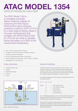
- 1. TYPICAL APPLICATIONS • Liquefied petroleum gas • Gasoline • Naphthas/Kerosenes • Crude oil • Fuel oil ATAC MODEL 1354VAPOUR PRESSURE ANALYSER The ATAC Model 1354 is a completely automatic Vapour Pressure Analyser for measuring the Reid Vapour Pressure (the vapour pressure exerted by a liquid at 100°F/37.8°C) for a wide range of refinery streams. Accurate measurements that correlate with ASTM D323 (D1267 for LPG) can be made on samples having viscosities up to 80cP at the measurement temperature. PRINCIPLE OF OPERATION The Model 1354 RVP analyser schematic is shown in Figure 1. The measured sample flows under constant temperature and pressure through a nozzle which is mounted inside a venturi shaped aspirator. As the sample is forced through the nozzle, its fluid velocity increases. This creates a pressure drop sufficient to vaporise the liquid. The relationship between the fluid velocity and pressure is given by the flow energy equation: (V1 )2 + P1 = (V2 )2 + P2 + F2 where V1 = Fluid velocity at inlet V2 = Fluid velocity at outlet P1 = Inlet pressure P2 = Outlet pressure F2 = Fluid friction loss If V2 is sufficiently large while V1 and P1 are held constant then, ignoring friction, the pressure of the fluid out of the nozzle can be reduced to the effective vapour pressure of the sample. Since the fluid temperature is held constant and the pressure at the nozzle inlet is maintained at a level that causes vaporisation of the sample, the pressure at the nozzle output is effectively the Kinetic Vapour Pressure (KVP).Figure 1: Model 1354 schematic • Fast, continuous vapour pressure analysis • Correlates to ASTM D323/D1267 and IP69 test methods • Exceeds test method repeatability • Accurate, reliable absolute pressure measurement • Industry standard communications - HART, Fieldbus or Modbus • Repeatability of 0.1 psi (0.007 bar) ATAC_Loose Insert.indd 1 20/3/14 3:24 pm
- 2. SPECIFICATIONS Analyser performance Accurate measurements can be made from samples having viscosities up to 80cP Available ranges From 0-1.6 barA standard (other spans and other units of measurement available) Repeatability ±0.007 bar (0.1 psi) Precision Within ASTM D323 (ASTM D1267 for LPG) Response time Better than 50 seconds Output signal Range: 4-20mA fully isolated loop powered and/or digital output depending on selected transmitter Out-of-service alarm contact signalling mains failure (or off) or bath temperature fuse blown. 2 sets c/o contacts rated at 25A @ 250V or 12A @ 120V Sample pressure (g) Depends on the back pressure at the analyser outlet but must normally exceed [outlet pressure (bar) x 2.5] +7 bar. Standard max pressure 60 bar (870 psi) Sample temperature Should remain within the range 25°C-50°C (77°F-120°F). Fluctuations must be minimal and not exceed 5°C (9°F). Sample flow 55-230 litres/hour (12-50 gallons/hour) depending on back pressure Sample conditioning Complete sample systems can be supplied to pre-condition process sample to the conditions required at the analyser inlet. Sample disposal Return to process or a recovery system. Sample recovery systems can be supplied. Power supply Voltage 115V or 230V ±10% single phase. Frequency 50 or 60Hz. Consumption 2.0 kVA Cooling water A supply of potable water at up to 135 l/h (30gal/h) and at a temperature ≤30°C (maximum pressure 7 barg) should be provided to carry away excess heat. The necessary coil is fitted as standard. If potable water is not available alternative cooling coil materials can be provided. Oil for temperature bath 11 litres (2.5 gal) of Shell Thermia B or equivalent. Reid vapour pressure tests are carried out at 37.8°C (100°F), but with this analyser, temperatures up to 110°C (240°F) may be selected and controlled to ±0.1°C. Local display Gauge indicates absolute vapour pressure. 0-100% linear scale on the transmitter Standard connections Sample inlet : ⅜” NPT(male) Sample outlet : ⅜” NPT (male) Cooling water : ¼” NPT (female) IN Cooling water : ¼” NPT (female) OUT Electrical ISO M20 Standard (½” NPT NEC) Signal out : As transmitter specification, either EExd or EExia with 4-20mA isolated output and / or digital output. Explosion protection options This analyser is ATEX certified for use in Zone 1 hazardous areas II 2G EEx d e ia IIB T4 Certificate no. ITS 09ATEX16356X Option: II 2G EEx d e ia IIB + H2 T4 Certificate no. ITS 09ATEX16357X Environmental protection Will operate satisfactorily under normal ambient temperature conditions between 0 and 55°C (32-130°F) but should be sheltered from direct sun and rain - see options below. Frost protection is recommended for water cooled analysers. Dimensions Width: 500mm Length: 900mm Height: 1400mm Weight: 180kg *Allow Extra for Access Mounting Floor fixing bolt holes (4 off 5 /8 ” dia) at 448mm (175 /8 ”) x 351mm (1313 /16 ”) centres Options • Configuration for CSA local approval • Cooling coil in Hastelloy C or Monel • Digital bath temperature transmitter and/or indicator instead of mercury thermometer • Choice of pressure transmitter to include HART, Foundation Fieldbus or Modbus communications. (Remote diagnostics from DCS or hand held communicator) • Environmental protection to IP65 • ATEX IIB + H2 certification Analytical Technology & Control Limited Broadway, Market Lavington SN10 5RQ, UK T +44 (0) 1380 818411 F +44 (0) 1380 812733 E sales@atacgroup.com W www.atacgroup.com An Advanced Company The precision behind the process ATAC-VPA-001-R0-EN-MAR-2014 This pressure is measured by an absolute pressure transmitter which gives a continuous output and is calibrated to equal the Reid Vapour Pressure (RVP). A back pressure regulator prevents back flow of the sample and vaporisation in the output line. The sample passes through a pressure regulating valve before the nozzle to maintain a constant inlet pressure. Critical components are immersed in an oil bath at a fixed temperature which is controlled by a precision temperature controller, heater and, when necessary, cooling water. The temperature is monitored by the relevant ASTM (IP) thermometer. The analyser can be fitted with the customer’s choice of pressure transmitter to include either a 4-20mA with HART output or the alternatives of Foundation Fieldbus or Modbus communications. ATAC_Loose Insert.indd 2 20/3/14 3:24 pm