H2600 HY-ALERTA SAFETY SYSTEMS – HY-ALERTA 2600
•
1 like•96 views

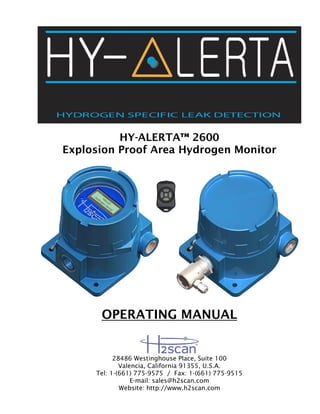
H2scan’s HY-ALERTA™ 2600 Explosion Proof Area Hydrogen Monitor provides hydrogen-specific leak detection and measurement for hydrogen concentrations as low as 4000 ppm and can be scaled to any concentration up to 5% hydrogen by volume, a range representing 10% to 125% of hydrogen’s lower flammability limit.

Recommended
More Related Content
Similar to H2600 HY-ALERTA SAFETY SYSTEMS – HY-ALERTA 2600
Similar to H2600 HY-ALERTA SAFETY SYSTEMS – HY-ALERTA 2600 (20)
More from European Tech Serv
More from European Tech Serv (20)
Recently uploaded
Recently uploaded (20)
H2600 HY-ALERTA SAFETY SYSTEMS – HY-ALERTA 2600
- 1. HY-ALERTA™ 2600 Explosion Proof Area Hydrogen Monitor OPERATING MANUAL 28486 Westinghouse Place, Suite 100 Valencia, California 91355, U.S.A. Tel: 1-(661) 775-9575 / Fax: 1-(661) 775-9515 E-mail: sales@h2scan.com Website: http://www.h2scan.com
- 2. HY-ALERTA™ 2600 Explosion Proof Area Hydrogen Monitor OPERATING MANUAL 90000015 R5, International Release Page 2 of 29 ECO 10-062 Mission Statement To become the leading provider of hydrogen specific safety monitoring and in-line process measurement systems where hydrogen gas is produced, used, consumed, stored and transported. We are committed to providing cost-effective solutions as new installations and replacements for existing hydrogen gas analyzers to OEM customers and through our global distribution network. Our products will achieve worldwide recognition in industrial safety and process applications based on superior products, while maintaining excellent relationships with and ensuring unsurpassed value to our business partners around the globe.
- 3. HY-ALERTA™ 2600 Explosion Proof Area Hydrogen Monitor OPERATING MANUAL 90000015 R5, International Release Page 3 of 29 ECO 10-062 CONTENTS 1 SPECIFICATIONS.............................................................................................................5 2 DESCRIPTION ..................................................................................................................7 2.1 System .....................................................................................................................................................7 2.1.1 Sensor Module.................................................................................................................................7 2.1.2 Control Module.................................................................................................................................7 3 INSTALLATION ................................................................................................................8 3.1 Unit Location...........................................................................................................................................8 3.2 Hydrogen Sensing Considerations.......................................................................................................8 3.3 Sensor Module........................................................................................................................................9 3.3.1 Sensor Module Mounting .................................................................................................................9 3.3.2 Gas Connection ...............................................................................................................................9 3.3.3 Sensor Module Wiring....................................................................................................................10 3.4 Control Module .....................................................................................................................................11 3.4.1 Control Module Mounting...............................................................................................................11 3.4.2 Display Board.................................................................................................................................11 3.4.3 Control Module Wiring....................................................................................................................12 3.4.3.1 AC Power Wiring............................................................................................................................12 3.4.3.2 Output Signal Wiring ......................................................................................................................13 3.4.3.3 RS422 Interface Wiring..................................................................................................................13 3.4.3.4 Sensor Cable Wiring ......................................................................................................................14 4 OPERATION ...................................................................................................................15 4.1 Startup ...................................................................................................................................................15 4.2 Settings..................................................................................................................................................15 4.3 Infrared Remote Control ......................................................................................................................15 4.3.1 Configuration Menu........................................................................................................................15 4.4 Serial Communication..........................................................................................................................22 5 MAINTENANCE ..............................................................................................................27 5.1 Cleaning.................................................................................................................................................27 5.2 Field Calibration....................................................................................................................................27 5.2.1 Gases.............................................................................................................................................27 5.2.2 Calibration ......................................................................................................................................27 5.2.3 Clear Field Cal ...............................................................................................................................28
- 4. HY-ALERTA™ 2600 Explosion Proof Area Hydrogen Monitor OPERATING MANUAL 90000015 R5, International Release Page 4 of 29 ECO 10-062 IMPORTANT NOTICES Read and understand this operating manual before operating or servicing the unit. HYDROGEN IS FLAMMABLE AT 4% IN AIR. TAKE INDICATIONS SERIOUSLY AND BE PREPARED TO TAKE ACTION. IN THE EVENT OF DETECTION OF 4% OR HIGHER OF A HYDROGEN GAS CONCENTRATION THERE IS A HIGH PROBABILITY OF A HAZARD TO SAFETY. INFORM LOCAL EMERGENCY RESPONSE PERSONNEL IMMEDIATELY. LIMITATION OF LIABILITY IN THE EVENT OF A DEFECT IN A PRODUCT, H2SCAN SHALL NOT BE RESPONSIBLE FOR ANY DIRECT, INDIRECT, INCIDENTAL OR CONSEQUENTIAL DAMAGES RESULTING THEREFROM, INCLUDING, BUT NOT LIMITED TO, LOSS OF REVENUE AND/OR PROFIT. LIMITED WARRANTY H2scan Limited Warranty. Each hydrogen instrument (“Product”) will conform, as to all substantial operational features, to the Product specifications set forth this Manual and will be free of defects which substantially affect such Product’s performance for twelve (12) months from the ship date for such Product. Must Provide Notice of Defect. If you believe a Product is defective, you must notify H2scan in writing, within ten (10) days of receipt of such Product, of your claim regarding any such defect. Return Product to H2scan for Repair, Replacement or Credit. If the Product is found defective by H2scan, H2scan’s sole obligation under this warranty is to either (i) repair the Product, (ii) replace the Product, or (iii) issue a credit for the purchase price for such Product, the particular remedy to be determined [by H2scan] on a case-by-case basis. Voided Warranty. H2scan’s 12 Month Limited Warranty is void for any of the following: The unit is opened and the manufacturing seal is broken Unauthorized repair work performed at the customer’s location or carried out by anyone other than H2scan’s factory trained technicians Equipment or parts that have been tampered with, misused, neglected, mishandled, improperly adjusted, or modified in any way without the written consent of H2scan. Equipment or parts that have been damaged due to shipping, misuse, accidents, mishandling, neglect, or problems with electrical power sources. Repair work performed during the warranty period does not prolong the warranty period past the original period. System operation in incorrect or inappropriate environments. Usage that is not in accordance with system guidelines or an operator’s failure to follow manual instructions. Limitation of Warranty. THE ABOVE IS A LIMITED WARRANTY AS IT IS THE ONLY WARRANTY MADE BY H2SCAN. H2SCAN MAKES NO OTHER WARRANTY EXPRESS OR IMPLIED AND EXPRESSLY EXCLUDES ALL WARRANTIES OF MERCHANTABILITY AND FITNESS FOR A PARTICULAR PURPOSE. YOUR SOLE REMEDY HEREUNDER IS REPAIR OR REPLACEMENT OF THE PRODUCT OR A CREDIT FOR THE PURCHASE PRICE FOR SUCH PRODUCT, THE PARTICULAR REMEDY TO BE DETERMINED BY H2SCAN ON A CASE-BY-CASE BASIS. H2SCAN SHALL HAVE NO LIABILITY WITH RESPECT TO ITS OBLIGATIONS UNDER THIS AGREEMENT FOR CONSEQUENTIAL, EXEMPLARY, OR INCIDENTAL DAMAGES EVEN IF IT HAS BEEN ADVISED OF THE POSSIBILITY OF SUCH DAMAGES. THE STATED EXPRESS WARRANTY IS IN LIEU OF ALL LIABILITIES OR OBLIGATIONS OF H2SCAN FOR DAMAGES ARISING OUT OF OR IN CONNECTION WITH THE DELIVERY, USE OR PERFORMANCE OF THE PRODUCTS.
- 5. HY-ALERTA™ 2600 Explosion Proof Area Hydrogen Monitor OPERATING MANUAL 90000015 R5, International Release Page 5 of 29 ECO 10-062 1 Specifications Sensitivity Range: 0.4% to 5% hydrogen by volume at 1ATM in air, 10% to 125% hydrogen lower flammable limit Accuracy: ± (0.03 x indication + 0.2) percent hydrogen by volume, example: accuracy at 1% H2 is ±0.23% H2 Response Time: T90 of 60 sec maximum Temperature: Ambient Temperature: 4°C to 60°C (40°F to 140°F) Storage: -40 to +50 °C Humidity: 0% to 95% RH Radiation: 350 Rads TID Input Power: 90VAC to 260VAC, 15W, 50Hz to 60Hz Analog Output: Isolated and self-powered 4-20mA, Maximum load impedance: 700Ω Relay Contacts: Two programmable 5A, 250VDC/VACMAX SPDT relays with both normally open (N.O.) and normally closed (N.C.) contacts. Serial Communication: RS422 Controls: Full access to all maintenance and calibration functions via infrared remote control Sensor Wiring: 8-pair, 22AWG (up to100') AC Power Wiring: 3-wire,14AWG 4-20mA Output Wiring: 1-pair, 22AWG RS-422 Output Wiring: 2-pair, 22AWG Verification Interval: 90 days Dimensions: See following figures (dimensions in inches) Sensor Module Weight: 2.6kg (5.8lbs) Control Module Weight: 2.7kg (5.9lbs) Product Life Expectancy: 10 years Explosion Proof Housing Certifications: (Sensor Assembly Not Certified) Class I, Groups B, C, D Class II, Groups E, F, G Class III Type 4X Class I, Zone 1, AEx d IIC Ex d IIC IP 66 UL 1203 FM3615 CSA C22.2 No. 30 UL 50 UL 60079-0/UL 60079-1 CSA 60079-0/CSA 60079-1 IEC 60529
- 6. HY-ALERTA™ 2600 Explosion Proof Area Hydrogen Monitor OPERATING MANUAL 90000015 R5, International Release Page 6 of 29 ECO 10-062 Figure 1: Control Module Dimensions (in inches) Figure 2: Sensor Module Dimensions (in inches)
- 7. HY-ALERTA™ 2600 Explosion Proof Area Hydrogen Monitor OPERATING MANUAL 90000015 R5, International Release Page 7 of 29 ECO 10-062 2 Description 2.1 System H2scan’s HY-ALERTA™ 2600 Explosion Proof Area Hydrogen Monitor provides hydrogen-specific leak detection and measurement for hydrogen concentrations as low as 4000ppm and can be scaled to any concentration up to 5% hydrogen by volume, a range representing 10% to 125% of hydrogen’s lower flammability limit. H2scan’s hydrogen-specific sensor technology has no cross sensitivity to other combustible gases, eliminating false positive alarms and ensuring safety system reliability. The HY-ALERTA™ 2600 consists of two modules and a wireless remote control. The Sensor Module houses the hydrogen sensor and the Control Module houses the LCD display and control circuitry. 2.1.1 Sensor Module The sensor module is in an explosion proof enclosure and is designed to be mounted on either the ceiling or wall above areas where hydrogen gas is stored or transported. It has ¾ inch NPT fittings at the two interface conduit ports and is painted “safety blue.” The Sensor Cup Assembly enables the installation of the plumbing required for the on-site calibration of the hydrogen sensor. 2.1.2 Control Module The Control Module is in an explosion proof enclosure with a glass window to view the LCD. The operational menus for the HY-ALERTA™ 2600 are accessed by an Infrared Remote Control through the glass window to the Control Module. This module receives the input power, delivers the isolated self-powered 4ma to 20mA analog output, provides the relay output signals, and establishes RS422 serial communication. It has ¾ inch NPT fittings at its three conduit ports and is painted “safety blue.”
- 8. HY-ALERTA™ 2600 Explosion Proof Area Hydrogen Monitor OPERATING MANUAL 90000015 R5, International Release Page 8 of 29 ECO 10-062 3 Installation Warning: if the unit is installed in a restricted location then it is the responsibility of the user and installer to make connections to related equipment in a manner consistent with the location classification. 3.1 Unit Location Though the unit can be mounted in any orientation or position, it is important to consider the possible sources and areas of accumulation of hydrogen gas. Typical installations are near the ceiling level or on the ceiling above equipment using or storing hydrogen. For earlier detection, artificial means of accumulation such as flat plates or inverted trays can be installed at lower heights to allow hydrogen to reach the sensor more quickly. Warning: it is not the intent of this manual to specify mounting location(s). It is the responsibility of the user and installer to determine the proper location(s) for hydrogen detection based upon the particular uses of hydrogen at the installation site. 3.2 Hydrogen Sensing Considerations From any given source, hydrogen gas disperses rapidly and generally upward due to the very low density of hydrogen compared to air. Understanding this behavior allows technicians to more effectively position the sensor to detect hydrogen leaks. If the sensor element is near (and above) the leak, the concentration will likely be higher but the leak may be difficult to locate. As hydrogen dissipates (generally above the leak), the concentration decreases. Generally, greater distances will increase the chance of intercepting the leak stream, but if the sensor is too far away, the response may be too weak to detect. When drafts or air currents are present, hydrogen will tend to be dispersed. Testing for hydrogen leaks downwind of the leak area may increase the chance of detecting the leak. If hydrogen is rising in an enclosed building (where there may be a layer of hot air near the ceiling), the hot air near the ceiling may have a lower density and act to retard the hydrogen from continuing to rise as rapidly as it did in lower layers of air. Thus, sensing hydrogen near ceiling areas with high temperatures present may not be as effective. Low temperatures can also affect the behavior of hydrogen. Hydrogen stored in a liquid state is at an extremely low temperature. The low temperature of any escaping hydrogen will be of a higher than normal density and may initially move downward. As the hydrogen warms, it will begin to rise upward. When checking for a leak in areas where liquid hydrogen is stored, check both above and below the area of concern.
- 9. HY-ALERTA™ 2600 Explosion Proof Area Hydrogen Monitor OPERATING MANUAL 90000015 R5, International Release Page 9 of 29 ECO 10-062 3.3 Sensor Module 3.3.1 Sensor Module Mounting Mounting is achieved with two ¼ inch screws through mounting holes in the base of the explosion proof housing. ¾ inch solid conduit threaded into the enclosure will also serve as further structural support. The housing can be mounted in any orientation or position on ceilings, the preferred location for the Sensor Module. When mounting the Sensor Module on walls, it is recommended to position the sensor to the left or right of the Sensor Module rather than towards the floor or the ceiling. When the sensor is directed towards the ceiling, dust and debris could accumulate, blocking the sensor. Since hydrogen gas tends to accumulate at the ceiling, directing the sensor towards the floor may move the sensor furthest away from the highest hydrogen gas concentration. Recommended Wall Mounted Sensor Module Positioning Sensor directed to the left or right Not Recommended Wall Mounted Sensor Module Positioning Sensor directed up or down 3.3.2 Gas Connection Gases are applied to the sensor during Field Calibration via ¼ inch tubing attached to the Sensor Cup Assembly on the Sensor Module. The Sensor Cup Assembly on the Sensor Module can be rotated to accommodate the plumbing of the calibration gases applied to the sensor. Plumbing from the Sensor Cup Assembly to the calibration control area is the responsibility of the installer.
- 10. HY-ALERTA™ 2600 Explosion Proof Area Hydrogen Monitor OPERATING MANUAL 90000015 R5, International Release Page 10 of 29 ECO 10-062 3.3.3 Sensor Module Wiring The Sensor Interface printed circuit board has a 16-pin terminal block, J1, for the Sensor Cable connection to the Control Module. It is a two piece design in which the wires are screwed into a receptacle in standard terminal block style. The receptacle plugs into a header mounted on the Sensor Interface Board. This cable provides DC power to the Sensor Module and digital communication signals between Sensor and Control Modules. Sensor Interface Board: J1 16-Pin Terminal Block for the Sensor Cable Pin Number Function 1 Pair 1 + 2 Pair 1- 3 Pair 2 + 4 Pair 2 - 5 Pair 3 + 6 Pair 3 - 7 Pair 4 + 8 Pair 4 - 9 Pair 5 + 10 Pair 5 - 11 Pair 6 + 12 Pair 6 - 13 Pair 7 + 14 Pair 7 - 15 Pair 8 + 16 Pair 8 - J1 pin 1
- 11. HY-ALERTA™ 2600 Explosion Proof Area Hydrogen Monitor OPERATING MANUAL 90000015 R5, International Release Page 11 of 29 ECO 10-062 3.4 Control Module 3.4.1 Control Module Mounting Mounting is achieved with two ¼ inch screws through mounting holes in the base of the explosion proof housing. ¾ inch solid conduit threaded into the enclosure will also serve as further structural support. The Control Module is mounted in an accessible location up to 100 feet away from the Sensor Module. This allows an installation of the Control Module at an accessible eye-level position. 3.4.2 Display Board The Display Board provides the LCD for local readouts and the infrared receiver for the infrared remote control. The Display Board connects with the Interface Board via a 10-pin cable. The cable allows the Display Board to be moved aside as electricians are wiring the Control Module. The Display Board is seated into place with four banana plugs so no tools are required. The Display Board banana plug legs are inserted into standoffs arranged in a symmetrical pattern so the Display Board is can be rotated into one of four different 90 degree increments when installed. In this way, the LCD will be displayed in the best position possible no matter how the Control Module enclosure is mounted.
- 12. HY-ALERTA™ 2600 Explosion Proof Area Hydrogen Monitor OPERATING MANUAL 90000015 R5, International Release Page 12 of 29 ECO 10-062 3.4.3 Control Module Wiring 3.4.3.1AC Power Wiring The Power Board has a 4-pin terminal block, J2, for the Power Cable connection to input AC power. It is a two piece design in which the wires are screwed into a receptacle in standard terminal block style, similar to the Sensor Module. If not implementing separate chassis and signal ground connections, pins 3 and 4 should be connected together with a jumper. Power Board: J2 4-Pin Terminal Block for the Power Cable Pin Number Function Description 1 LINE Hot or active contact from 90VAC to 260VAC power supply providing the alternating current 2 NEUTRAL Contact completes the circuit, returning the alternating current to the power supply 3 CHASSIS GROUND Safety connection to earth or ground to take faulty currents directly to ground 4 SIGNAL GROUND Common ground for sensitive circuitry isolated from chassis ground; if not implementing separate chasses and signal ground connections, pins 3 and 4 should be connected together with a jumper J2 pin 1 J5 pin 1 J3 pin 1
- 13. HY-ALERTA™ 2600 Explosion Proof Area Hydrogen Monitor OPERATING MANUAL 90000015 R5, International Release Page 13 of 29 ECO 10-062 3.4.3.2Output Signal Wiring The Interface board has an 8-pin terminal block, J5, for the Output Cable delivering a 4mA to 20mA analog output and two SPDT relays available for alert and alarm level switches. The two programmable relays have both normally open (N.O.) and normally closed (N.C.) contacts. Warning: do not exceed the 5A, 250Vdc/Vac maximum ratings of the alert and alarm relay contact specifications. Interface Board: J5 8-Pin Terminal Block for Output Cable Pin Number Function Description 1 4-20mA+ 2 4-20mA- Isolated and self-powered 4-20mA analog output, 700Ω maximum load impedance 3 ALERT NC 4 ALERT COM 5 ALERT NO SPDT Relay 1 for the Alert level of hydrogen 6 ALARM NC 7 ALARM COM 8 ALARM NO SPDT Relay 2 for the Alarm level of hydrogen 3.4.3.3RS422 Interface Wiring The Interface Board has a 4-pin terminal block, J3, for the RS422 Serial Interface Cable. Interface Board: J3 4-Pin Terminal Block for Serial Interface Cable Description J3 Pin TxD- (Device Transmit, Negative) 1 TxD+ (Device Transmit, Positive) 2 RxD- (Device Receive, Negative) 3 RxD+ (Device Receive, Positive) 4
- 14. HY-ALERTA™ 2600 Explosion Proof Area Hydrogen Monitor OPERATING MANUAL 90000015 R5, International Release Page 14 of 29 ECO 10-062 3.4.3.4Sensor Cable Wiring The Interface Board has a 16-pin terminal block, J4, for the Sensor Cable connection to the Sensor Module. The Sensor Cable can be a maximum length of 100 feet using 22AWG cable. Interface Board: J4 16-Pin Terminal Block for the Sensor Cable Pin Number Function 1 Pair 1 + 2 Pair 1- 3 Pair 2 + 4 Pair 2 - 5 Pair 3 + 6 Pair 3 - 7 Pair 4 + 8 Pair 4 - 9 Pair 5 + 10 Pair 5 - 11 Pair 6 + 12 Pair 6 - 13 Pair 7 + 14 Pair 7 - 15 Pair 8 + 16 Pair 8 -
- 15. HY-ALERTA™ 2600 Explosion Proof Area Hydrogen Monitor OPERATING MANUAL 90000015 R5, International Release Page 15 of 29 ECO 10-062 4 Operation 4.1 Startup Warning: before the system is powered on in a hazardous environment, technicians must confirm a complete system installation, including all electrical connections and wiring, unused cable ports are plugged, and explosion proof housing lids are screwed on tight and locked into position. Confirm all connections and apply power to the Control Module. Once power is applied, the LCD will display “Warmup” as the monitor executes a warm-up sequence lasting approximately 15 minutes. The Not Ready analog output during this Power-On Self Diagnostic Test will be 2mA. When the test is over, the monitor will come online, the LCD will read “Hydrogen = 0.0000%H2,” and the analog output will be 4mA. 4.2 Settings The monitor’s operational and output settings have been configured at H2scan. The following analog output parameters are set at the factory: Analog Output Range: 4mA to 20mA Not Ready (Power-On Self Diagnostic) Output: 2mA Sensor Error Output: 3mA Hydrogen Range: 0% to 5% hydrogen by volume Warning: if settings are changed from those set by the manufacturer then it is the user’s responsibility to understand the implications to the connecting equipment monitoring the unit. 4.3 Infrared Remote Control A 5 button Infrared Remote Control is used to access the Configuration Menu, change settings and initiate Calibration. Each Remote Control is configured specifically to communicate with its respective Control Module and is identified with corresponding serial numbers. H2scan cannot guarantee reliable operation between unmatched Remote Controls and Control Modules. If lost or damaged, spare Remote Controls can be purchased directly from H2scan with reference to the Remote Control and Control Module serial numbers. 4.3.1 Configuration Menu The Keypad on the remote control is used to alter the display or initiate special functions from the Configuration Menu: Pressing ▲ (up arrow button) displays the peak hydrogen reading. Pressing ▼ (down arrow button) displays the current percent hydrogen concentration. Pressing ► (right arrow button) clears the peak hydrogen value.
- 16. HY-ALERTA™ 2600 Explosion Proof Area Hydrogen Monitor OPERATING MANUAL 90000015 R5, International Release Page 16 of 29 ECO 10-062 Pressing and holding the button invokes the Configuration Menu. Pressing ▼ (down arrow button) scrolls down through function menus or scroll down through a numerical range. Pressing ▲ (up arrow button) scrolls up through function menus or scroll up through a numerical range. Pressing the button or ► (right arrow button) selects the function. Pressing ◄ (left arrow button) backs out of menus. The following functions are available found in the Configuration Menu: Information Disp – model information o Firmware Rev – firmware revision o Serial Number – model serial number o Calibration Date – date of last factory calibration Configure Relays – configure hydrogen levels where relays actuate o R1 Level – level of hydrogen detected where first relay will actuate; Alert Level (standard factory setting: 1% hydrogen by volume) o R2 Level – level of hydrogen detected where second relay will actuate; Alarm level (standard factory setting: 2% hydrogen by volume) Set H2 Range – define hydrogen sensitivity range (standard factory setting: 0% to 5% hydrogen by volume) o Low H2 Range – lowest level of hydrogen (standard factory setting: 0% hydrogen by volume) to correspond with the low range IDAC setting o High H2 Range – highest level of hydrogen (standard factory setting: 5% hydrogen by volume typical) to correspond with the high range IDAC setting Configure IDAC – define analog output range (standard factory setting: 4mA to 20mA) o Low Range – low level analog output (standard factory setting: 4mA) to correspond with lowest level of hydrogen range o High Range – high level analog output (standard factory setting: 20mA) to correspond with highest level of hydrogen range o Error – analog output (standard factory setting: 3mA) of error status
- 17. HY-ALERTA™ 2600 Explosion Proof Area Hydrogen Monitor OPERATING MANUAL 90000015 R5, International Release Page 17 of 29 ECO 10-062 o Not Ready –analog output (standard factory setting: 2mA) of self- diagnostic test Field Calibrate o Calibrate Sensor – Field Calibration procedure o Clear Field Cal - restores the instrument to the last factory calibration Exit – exit Configuration Menu to standard display output setting Configuration Menu See Hydrogen Menu See Info Display Menu See Relay Menu See H2 Range Menu See Configure IDAC Menu See Field Calibrate Menu Exiting Menu Delay
- 18. HY-ALERTA™ 2600 Explosion Proof Area Hydrogen Monitor OPERATING MANUAL 90000015 R5, International Release Page 18 of 29 ECO 10-062 Hydrogen Menu Information Disp Menu 3 Second Delay
- 19. HY-ALERTA™ 2600 Explosion Proof Area Hydrogen Monitor OPERATING MANUAL 90000015 R5, International Release Page 19 of 29 ECO 10-062 Configure Relay Menu Set H2 Range Menu
- 20. HY-ALERTA™ 2600 Explosion Proof Area Hydrogen Monitor OPERATING MANUAL 90000015 R5, International Release Page 20 of 29 ECO 10-062 Configure IDAC Menu
- 21. HY-ALERTA™ 2600 Explosion Proof Area Hydrogen Monitor OPERATING MANUAL 90000015 R5, International Release Page 21 of 29 ECO 10-062 Field Calibrate Menu Good? No Yes Good?No Yes Good?No Yes
- 22. HY-ALERTA™ 2600 Explosion Proof Area Hydrogen Monitor OPERATING MANUAL 90000015 R5, International Release Page 22 of 29 ECO 10-062 4.4 Serial Communication The user can monitor output and interface with the unit in order to perform calibration or adjust user settings via the serial communication connector. The serial communication is accomplished via an RS422 interface. Serial Communications Software - Any serial port two-way communications software such as terminal emulators (HyperTerminal, Telnet, etc.) and purpose-built software (using LabView, Visual Basic, C++, etc.) can be used to establish serial communication with the unit. RS422Format and Settings – 19200 Baud 8 bit data 1 stop bit No parity Data Display – Streaming data is presented in column format. Once serial communication is established and the unit is operating in normal mode, data will be displayed in the user specified format. The display output options are configured via a serial command as described in the following section. Data available is: <fmt> Format (these appear in their own columns) Timestamp (an integer count at 0.25 sec intervals) Printed Circuit Board (PCB) Temperature in C Sensor Temperature in C Raw Analog Data Converter (ADC) Values Calibrated Hydrogen Values Peak Hydrogen Values <opt> Options (these status data appear in the MESSAGES column) Calculation Errors Heater State What follows are examples of typical user specified outputs: Example 1: Sample serial data with column headers– Calibrated H2% and Messages only Display User Response H2scan: Type “g 02 06” %H2 Messages 0.0000 0.0000 0.0000 Example 2: Sample serial data with column headers– Multiple Outputs Specified
- 23. HY-ALERTA™ 2600 Explosion Proof Area Hydrogen Monitor OPERATING MANUAL 90000015 R5, International Release Page 23 of 29 ECO 10-062 Display User Response H2scan: Type “g b2 06” Time stamp Pcb Temp Snsr Temp %H2 Messages 264 28.8530 124.50800 0.0000 280 29.1979 124.50910 0.0000 296 29.5169 124.51110 0.0000 312 29.7951 124.51320 0.0000 Serial Communication Commands – The unit can be communicated with and configured via the use of commands as described below. Two levels of communication outputs are available: Level 0 – Default level used for data monitoring and basic functions providing a continuous stream of data readings Level 1 – Password protected level used for configuration of user-settable parameters; interactive single-line data output per command Command Summary – The RETURN or ENTER key is the last character of the command string. If either key is pressed without a command string the result is an invalid command and will resume continuous display if in Level 0 or return to prompt if in Level 1. Level 0 Commands Keystroke Description ESC Stops continuous display to enter a password or command. If in level zero, the continuous display will resume after executing one command. (spacebar) Pressing the Space key while the serial output is active will display a label line showing the heading for each column of data. A Average readings. C Clear peak hydrogen value. =<password> Enter the password to change security level. A null or invalid password returns to the default security level. Level 0 password (resume normal operation) =0 Level 1 password (enter user command mode) =h2scan
- 24. HY-ALERTA™ 2600 Explosion Proof Area Hydrogen Monitor OPERATING MANUAL 90000015 R5, International Release Page 24 of 29 ECO 10-062 Level 1 Commands Keystroke Description A <R1> <R2> Set the R1 and R2 set points for the relay contacts in %H2. C Clear peak hydrogen value. D <page> Display Product Information. Enter page number 0-6 or A for all pages, default is page 0. 0 – Product information 1 – User configuration 2 – Manufacturing information 3 – Product configuration 4 – Sensor characterization data 5 – Hydrogen calibration data 6 – Temperature calibration data A – All of the above E Field Verify F Field Calibration G < fmt> <opt> Start or resume the sensor operation: if needed heat the ASIC, setup the sensor, and output data on serial port (restores default settings). For format <fmt> options see below. H <low> <high> Set the hydrogen reporting range: <low> to <high> in %H2. I <low> <high> <err> <not rdy> Set the DAC current output range: <low> to <high>; error output <err>; and not ready output <not rdy> milliamps. Possible range from 0 to 20 milliamps. L < fmt> <opt> Print current hydrogen reading. Used to poll for hydrogen readings. Default format <fmt> is current setting. P <atm> Select atmospheric pressure of gas. Default pressure is 0.9690 atm. R Reset the sensor: depending on sensor configuration will purge then zero the sensor before returning to normal operation. S Stop the sensor: turn off heater, set Bias to zero, set DAC outputs to zero, and stop reporting data on the serial output. V <low> <high> <err> <not rdy> Set the DAC voltage output range: <low> to <high>; error output <err>; and not ready output <not rdy> in volts. Possible range from 0 to 5 volts. X Clear field calibration data (returns to last factory calibration data)
- 25. HY-ALERTA™ 2600 Explosion Proof Area Hydrogen Monitor OPERATING MANUAL 90000015 R5, International Release Page 25 of 29 ECO 10-062 Format <fmt> - The Format <fmt> string is a two character hexadecimal representation of an 8 bit value derived from the following table. The user determines which data is needed and selects that bit value. Once all selections are made the values are summed bitwise and then converted to a two place hexadecimal value. To aid in the conversion, a 4 bit to hexadecimal conversion table follows in the following example. Format: Bit Value Identifiers Serial output Format <fmt> parameter: select the desired columns of data from this list, add the bit value for each column bitwise, and convert into two hexadecimal characters using the 4 bit-to-Hexadecimal table in in the following example. Description Bit Value Include time stamp 1 0 0 0 0 0 0 0 Include raw ADC values 0 1 0 0 0 0 0 0 Include PCB temperature 0 0 1 0 0 0 0 0 Include sensor temperature 0 0 0 1 0 0 0 0 Include capacitor reading 0 0 0 0 1 0 0 0 Include resistor reading 0 0 0 0 0 1 0 0 Include overall hydrogen reading 0 0 0 0 0 0 1 0 Include peak hydrogen reading 0 0 0 0 0 0 0 1 Options <opt> - The Options <opt> string is a two character hexadecimal representation of an 8 bit value derived from the following table. The user determines which data is needed and selects that bit value. Once all selections are made the values are summed bitwise and then converted to a two place hexadecimal value. To aid in the conversion, a 4 bit-to-Hexadecimal conversion table follows in the following example. Options: Bit Value Identifiers Serial output Options <opt> parameter: select the desired status messages from this list which will appear in the MESSAGES column, add the bit value for each column bitwise, and convert into two hexadecimal characters using the 4 bit-to-Hexadecimal table in the following example. Description Bit Value Calculation Errors 0 0 0 0 0 1 0 0 Heater State 0 0 0 0 0 0 1 0
- 26. HY-ALERTA™ 2600 Explosion Proof Area Hydrogen Monitor OPERATING MANUAL 90000015 R5, International Release Page 26 of 29 ECO 10-062 Example: The user wishes to implement the “G” command (“Go” command, refer to the LEVEL 1 COMMANDS table) to have the following serial output columns reported from the series HY-OPTIMA™ 1700 sensor: Time Stamp, Capacitor Reading, Overall Hydrogen Reading, the Peak Hydrogen Reading, Calculation Errors, and the Heater state. From the FORMAT <fmt> table above, you identify your desired columns with its corresponding bit value: <fmt> Descriptions <fmt> Bit Value Time Stamp 1000 0000 Capacitor Reading 0000 1000 Overall Hydrogen Reading 0000 0010 Peak Hydrogen Reading 0000 0001 <fmt> 4 Bit Value Combination: 1000 1011 Now use the 4 BIT-TO-HEXADECIMAL table above to convert this 4 bit value combination into a two place hexadecimal value: <fmt> Two Place Hexadecimal Value: 8b From the OPTIONS <opt> table above, you identify your desired columns with its corresponding bit value: <opt> Descriptions <opt> Bit Value Calculations Errors 0000 0100 Heater State 0000 0010 <opt> 4 Bit Value Combination: 0000 0110 Again, use the 4 BIT-TO-HEXADECIMAL table to convert this 4 bit value combination into a two place hexadecimal value: <opt> Two Place Hexadecimal Value: 06 Conclusion: To have the Time Stamp, Capacitor Reading, Overall Hydrogen Reading, the Peak Hydrogen Reading, Calculations Errors, and Heater State columns continuously reported, you will implement the “G” serial command (“Go” Command, refer to LEVEL 1 COMMANDS table) as follows at the H2scan: command prompt: G < fmt> <opt> = g 8b 06 Display User Response H2scan: Type “g 8b 06” 4 bit value Hexadecimal Character 0001 1 0010 2 0011 3 0100 4 0101 5 0110 6 0111 7 1000 8 1001 9 1010 A 1011 B 1100 C 1101 D 1110 E 1111 F
- 27. HY-ALERTA™ 2600 Explosion Proof Area Hydrogen Monitor OPERATING MANUAL 90000015 R5, International Release Page 27 of 29 ECO 10-062 5 Maintenance 5.1 Cleaning If the monitor is exposed to debris, condensation or other material that may collect over the sensor tip, then the monitor should be cleaned with the gentle wiping of a clean, lint-free cloth or paper towel. 5.2 Field Calibration 5.2.1 Gases Calibration requires the availability of the following certified gases (obtainable from H2scan or gas suppliers): zero grade, hydrogen-free air 2.00% hydrogen by volume in air (20,000 ppm) 5.2.2 Calibration The Calibrate function allows the user to perform a field calibration of the instrument. Calibrations do not cause any wear on the sensor and can be accomplished as often as desired. Analog outputs can be monitored through the user’s system. Below are the steps to carry out Field Calibration: FIELD CALIBRATION STEPS Step Display User response 1 Hydrogen = 0% Press the button to enter the Hydrogen Menu. 2 Information Disp Press ▼ four times until reaching the Field Calibrate Menu. 3 Field Calibrate XX/XX/XX Press the button. 4 Calibrate Sensor Press the button. 5 Calibrate Sensor Continue? Press the button. 6 Calibrate Sensor In Progress Calibration starts. 7 Apply 0.000%H2 Continue? Apply hydrogen-free, ultra-zero air to the Sensor through the gas plumbing to the fitting on the cup of the Sensor Module. Press the button. 8 Apply 0.000%H2 In Progress 0% hydrogen by volume Calibration starts. 9 Apply 0.000%H2 Settle Checking sensor temperature. 10 Hydrogen = 0% Wait XXXX Wait until xxxx = 0 for the sensor reading to stabilize. 11 Hydrogen = 0% Finding Average Measuring sensor response to test gas. 12 Apply 2.000%H2 Continue? Apply 2% hydrogen by volume with a balance of air to the Sensor through the gas plumbing to the fitting on the cup of the Sensor Module. Press the button.
- 28. HY-ALERTA™ 2600 Explosion Proof Area Hydrogen Monitor OPERATING MANUAL 90000015 R5, International Release Page 28 of 29 ECO 10-062 FIELD CALIBRATION STEPS Step Display User response 13 Apply 2.000%H2 In Progress 2% hydrogen by volume Calibration starts. 14 Apply 2.000%H2 Settle Checking sensor temperature. 15 Hydrogen = 2% Wait XXXX Wait until xxxx = 0 for the sensor reading to stabilize. 16 Hydrogen = 2% Finding Average Measuring sensor response to test gas. 17 Apply 0.000%H2 Continue? Apply hydrogen-free, ultra-zero air to the Sensor through the gas plumbing to the fitting on the cup of the Sensor Module. Press the button. 18 Apply 0.000%H2 In Progress 0% hydrogen by volume Calibration starts. 19 Apply 0.000%H2 Settle Checking sensor temperature. 20 Hydrogen = 0% Wait XXXX Wait until xxxx = 0 for the sensor reading to stabilize. 21 Hydrogen = 0% Finding Average Measuring sensor response to test gas. 22 Enter Date: 1.0000 M Select the current month (1-12) using the ▲ and ▼ keys. Press the button. 23 Enter Date: 1.0000 D Select the current day (1-31) using the ▲ and ▼ keys. Press the button. 24 Enter Date: 6.0000 Y Select the current year (2007=7, 2012=12, etc.) using the ▲ and ▼ keys. Press the button. 25 Calibrate Sensor Done Press the button. 26 Field Calibrate XX/XX/XX Press ▼. 27 Exit Press the button. 5.2.3 Clear Field Cal The Clear Field Calibration function restores the instrument to the last factory calibration. Once entered into the Clear Field Calibration function (see Section 4.3.1), the user is prompted through the routine as follows: Step Display User response 1 Clear Field Cal Are you sure? Press the button to clear field calibration values, any other key to exit.
- 29. HY-ALERTA™ 2600 Explosion Proof Area Hydrogen Monitor OPERATING MANUAL 90000015 R5, International Release Page 29 of 29 ECO 10-062 QUESTIONS? PLEASE CONTACT US AT: 28486 Westinghouse Place, Suite 100 Valencia, California 91355, U.S.A. Tel: (661) 775-9575 / Fax: (661) 775-9515 E-mail: sales@h2scan.com Website: http://www.h2scan.com Manual copyright © 2008, H2scan Instrument software copyright © 2006, H2scan Wide Range SensorTM protected under US patent number 5,279,795