Download as PDF, PPTX

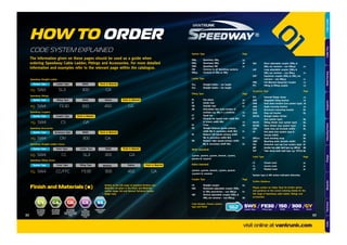

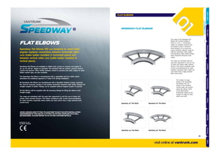

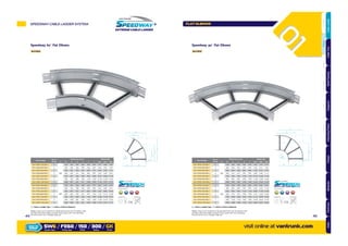
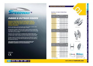
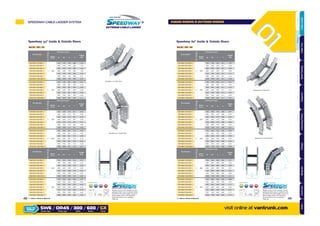
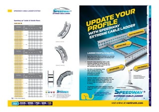
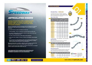
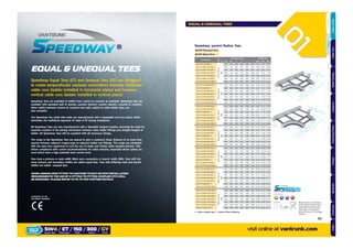

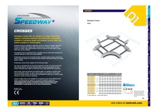

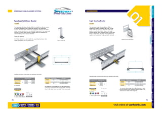
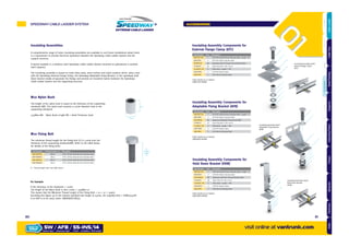
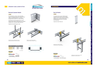
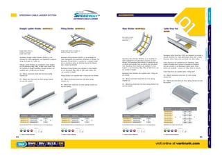
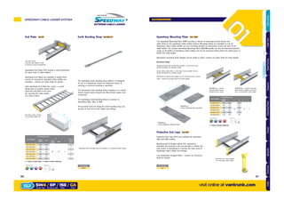
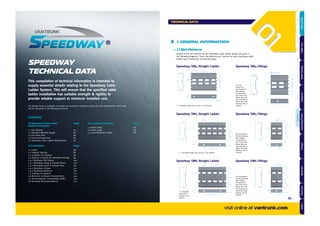
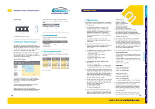
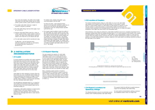
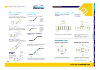

The document provides information about the Vantrunk Speedway Extreme Cable Ladder System. It describes the Speedway cable ladder system as representing a major advance in cable ladder design by providing faster and easier installation, greater cable fill capacity, and total flexibility. It then provides details on ordering the different components of the Speedway system, including ladder types, fitting types, widths, radii, coupler types, accessory types, and cover types.


![Getting Started with Apache Spark: Big Data Made Simple [Free Meetup]](https://cdn.slidesharecdn.com/ss_thumbnails/apachesparkgettingstarted-260203175547-8361bcc3-thumbnail.jpg?width=640&height=640&fit=bounds)


