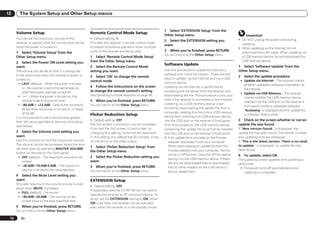
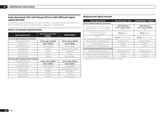
This document provides important safety instructions and warnings for an audio/video receiver. It cautions the user to read all instructions before use, keep children away from batteries, only use attachments specified by the manufacturer, and unplug during lightning storms. Ventilation openings should not be blocked to prevent overheating. It also provides instructions on volume levels for safe listening, handling power cords and plugs, cleaning, and troubleshooting.
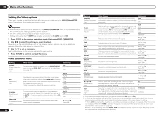
![Before you start 01
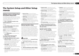
! Batteries with the same shape may have instructions on the screen to make the connec- this CD-ROM with a DVD player or music Wiring Navi only starts up automatically the
different voltages. Do not use different tions and settings. CD player can damage speakers or cause first time AVNavigator is launched.
batteries together. There are also other features enabling easy use impaired hearing due to the large volume. 2 Select and use the desired function.
! When disposing of used batteries, please of various functions, including an Interactive License AVNavigator includes the following functions:
comply with governmental regulations or Manual that operates in association with the ! Please agree to the “Terms of Use” indicated ! Wiring Navi – Guides you through
environmental public instruction’s rules that receiver, updating of various types of software, below before using this CD-ROM. Do not use if connections and initial settings in dialog
apply in your country or area. and MCACC Application that lets you check the you are unwilling to consent to the terms of its fashion. High precision initial settings can be
MCACC measurement results on 3D graphs. use. made easily.
Also agree to the “License Agreement” ! Interactive Manual – Automatically displays
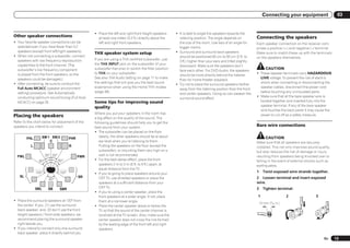
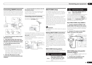
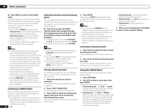
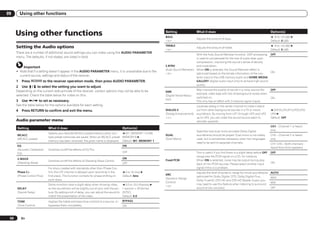
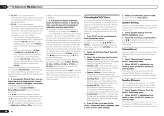
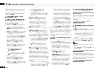
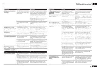
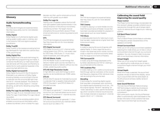
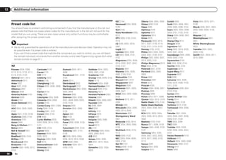
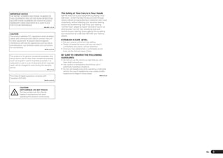
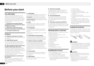
Operating range of remote Installing AVNavigator displayed when installing AVNavigator. the pages explaining the functions that have
control unit Terms of Use been operated on the receiver. It is also
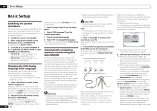
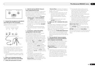
1 Load the included AVNavigator
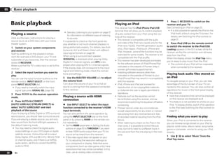
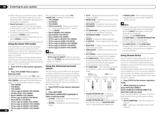
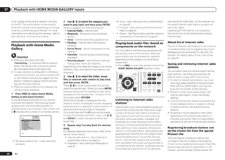
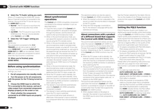
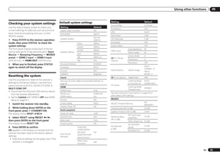
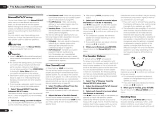
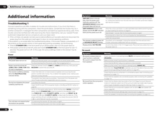
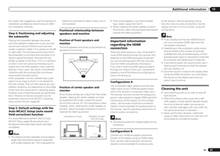
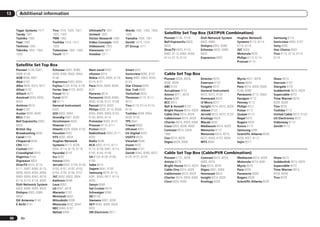
The remote control may not work properly if: ! Copyright to data provided on this CD-ROM possible to operate the receiver from the
CD-ROM into your computer’s CD drive. Interactive Manual.
! There are obstacles between the remote belongs to PIONEER CORPORATION.
! The installation screen is displayed. Proceed
control and the receiver’s remote sensor. Unauthorized transfer, duplication, broadcast, ! Glossary – Displays glossary pages.
to step 2.
! Direct sunlight or fluorescent light is shining public transmission, translation, sales, ! MCACC Appli – Displays Advanced
! If the installation screen does not appear,
onto the remote sensor. lending or other such matters that go beyond MCACC measurement results vividly on the
double-click on the CD-ROM icon then start
! The receiver is located near a device that is the scope of “personal use” or “citation” as computer.
the installer (AVNV_XXX_xxx.exe).
emitting infrared rays. defined by Copyright Law may be subject There are special operating instructions
! The receiver is operated simultaneously with 2 Follow the instructions on the screen to punitive actions. Permission to use this for MCACC Application. These instructions
another infrared remote control unit. to install. CD-ROM is granted under license by PIONEER are included in the AVNavigator
When “Finish” is selected, installation is CORPORATION. Interactive Manual’s menus. Refer to them
completed. when using MCACC Application.
General Disclaimer ! Software Update – Allows various types of
3 Remove the included AVNavigator ! PIONEER CORPORATION does not
CD-ROM from the computer’s CD drive. software to be updated.
guarantee the operation of this CD-ROM with ! Settings – Used to make various
respect to personal computers using any AVNavigator settings.
Handling the CD-ROM of the applicable OS. In addition, PIONEER ! Detection – Used to detect the receiver.
Operating Environment CORPORATION is not liable for any damages
30°
30° ! This CD-ROM can be used with Microsoft® incurred as a result of use of this CD-ROM
and is not responsible for any compensation. Note
Windows® XP/Vista/7.
The names of private corporations, products To use the AVNavigator of another model, first
! A browser is at times used for AVNavigator
and other entities described herein are the uninstall (delete) this receiver’s AVNavigator,
7 m (23 ft.) functions. The supported browser is Microsoft
registered trademarks or trademarks of their then install the AVNavigator of the other model.
Internet Explorer 6, 7 and 8. With other
browsers, some functions may be limited or respective firms.
Deleting the AVNavigator
the display may not appear properly.
About using AVNavigator Also, even with a supported browser, Using AVNavigator You can use the following method to uninstall
(included CD-ROM) depending on the browser’s settings, some (delete) the AVNavigator from your PC.
functions may be limited and the display may 1 Click [AVNavigator] on the desktop to
The included AVNavigator CD-ROM contains % Delete from the Control Panel of the
not appear properly. launch AVNavigator.
Wiring Navi allowing you to easily make the PC.
AVNavigator is launched and Wiring Navi
receiver’s connections and initial settings in Precautions For Use From the Start menu, click “Program”
starts up. The language selection screen
dialog fashion. High precision initial settings ! This CD-ROM is for use with a personal d “PIONEER CORPORATION” d
appears. Follow the instructions on the screen
can be completed easily simply by following the computer. It cannot be used with a DVD “AVNavigator(VSX-53 or VSX-52)” d “Uninstall”.
to make the connections and automatic
player or music CD player. Attempting to play settings.
En 7](https://image.slidesharecdn.com/vsx-52operatinginstructions051911-111202034130-phpapp01/85/Vsx-52-operating-instructions051911-7-320.jpg)
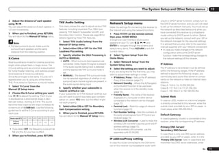
![Controls and displays 02
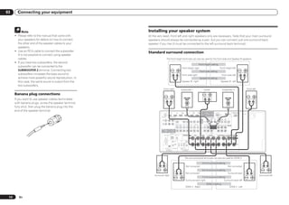
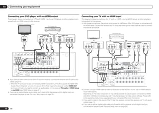
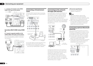
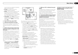
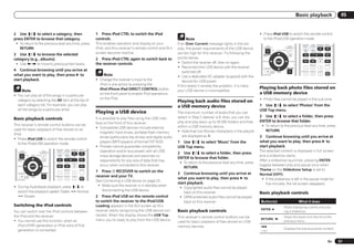
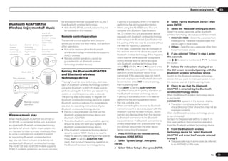
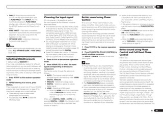
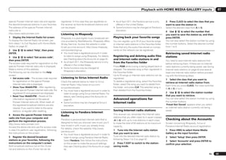
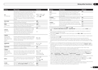
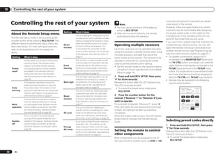
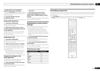
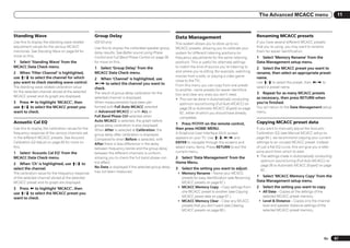
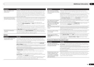
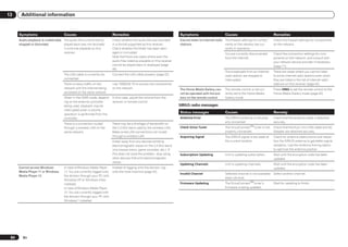
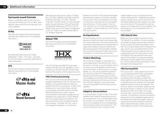
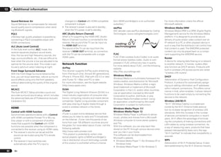
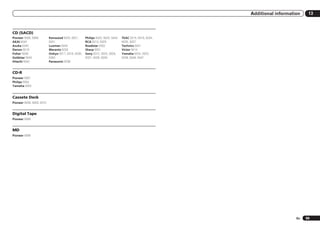
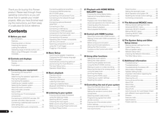
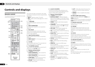
7 (PHASE CONTROL) 17 Matrix decoding format indicators
Display Lights when the Phase Control (page 39) or Full ! 2PRO LOGIC IIx – This lights to indicate 2
Band Phase Control (page 39) is switched on. Pro Logic II / 2 Pro Logic IIx decoding (page
1 2 3 4 5 6 7 8 9 10 11 12 13 14
Full Band Phase Control is only apply to the 37).
AUTO L C R 2DIGITAL PLUS DSD PCM FULL BAND TUNED VSX-53. ! Neo:6 – When one of the Neo:6 modes of the
2TrueHD MULTI-ZONE PQLS ALC ATT STEREO
HDMI SL SR DTS HD ES 96/24 S.RTRV SOUND UP MIX OVER MONO dB
receiver is on, this lights to indicate Neo:6
DIGITAL XL XC XR 8 Analog signal indicators processing (page 37).
ANALOG LFE MSTR CD TUNER SIRIUS DVD TV VIDEO HMG USB Light to indicate reducing the level of an analog
AUTO SURROUND iPod BD DVR HDMI [ 2 ] [ 3 ] [ 4 ]
signal (page 54). 18 S.RTRV
STREAM DIRECT
2PROLOGIC x Neo:6 Lights when the Auto Sound Retriever function
THX ADV.SURROUND
STANDARD
9 SOUND is active (page 50).
SP AB SLEEP Lights when the DIALOG E (Dialog
6 15 16 17 18 19 20 Enhancement) or TONE (tone controls) features 19 Character display
is selected (page 50). Displays various system information.
1 Signal indicators ! 96/24 – Lights with DTS 96/24 decoding. 10 Tuner indicators 20 Remote control mode indicator
Light to indicate the currently selected input ! DSD PCM – Light during DSD (Direct Stream ! TUNED – Lights when a broadcast is being Lights to indicate the receiver’s remote control
signal. AUTO lights when the receiver is set to Digital) to PCM conversion with SACDs. received. mode setting. (Not displayed when set to 1.)
select the input signal automatically (page 39). ! PCM – Lights during playback of PCM ! STEREO – Lights when a stereo FM (page 74)
2 Program format indicators signals. broadcast is being received in auto stereo
Light to indicate the channels to which digital ! MSTR – Lights during playback of DTS-HD mode.
signals are being input. Master Audio signals. ! MONO – Lights when the mono mode is set
! L/R – Left front/Right front channel 4 MULTI-ZONE using MPX.
! C – Center channel Lights when the MULTI-ZONE feature is active 11
! SL/SR – Left surround/Right surround (page 53). Lights when the sound is muted.
channel 5 FULL BAND
! LFE – Low frequency effects channel (the (( )) 12 Master volume level
VSX-53 only: Lights when the Full Band Phase Shows the overall volume level.
indicators light when an LFE signal is being Control is switched on (page 39).
input) “---” indicates the minimum level, and “+12dB”
! XL/XR – Two channels other than the ones 6 Listening mode indicators indicates the maximum level.
above ! AUTO SURROUND – Lights when the Auto 13 Input function indicators
! XC – Either one channel other than the ones Surround feature is switched on (page 37). Light to indicate the input function you have
above, the mono surround channel or matrix ! ALC – Lights when the ALC (Auto level selected.
encode flag control) mode is selected (page 37).
! STREAM DIRECT – Lights when Direct/Pure 14 Scroll indicators
3 Digital format indicators Direct is selected (page 38). Light when there are more selectable items
Light when a signal encoded in the correspond- ! ADV.SURROUND – Lights when one of when making the various settings.
ing format is detected. the Advanced Surround modes has been 15 Speaker indicators
! 2 DIGITAL – Lights with Dolby Digital selected (page 38). Lights to indicate the current speaker system
decoding. ! STANDARD – Lights when one of the using SPEAKERS (page 53).
! 2 DIGITAL PLUS – Lights with Dolby Digital Standard Surround modes is switched on 16 SLEEP
Plus decoding. (page 37). Lights when the receiver is in sleep mode (page
! 2 TrueHD – Lights with Dolby TrueHD ! THX – Lights when one of the Home THX 54).
decoding. modes is selected (page 38).
! DTS – Lights with DTS decoding.
! DTS HD – Lights with DTS-HD decoding.
En 9](https://image.slidesharecdn.com/vsx-52operatinginstructions051911-111202034130-phpapp01/85/Vsx-52-operating-instructions051911-9-320.jpg)
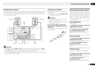
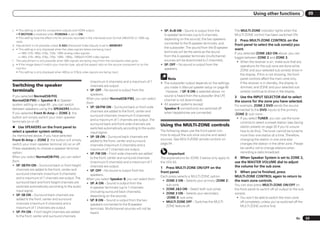
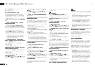
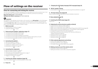
![03 Connecting your equipment
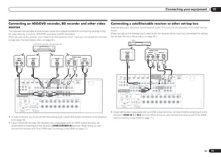
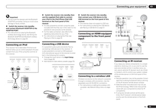
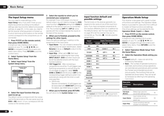
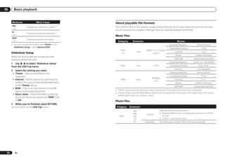
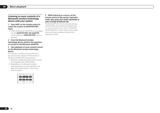
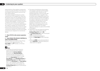
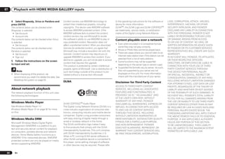
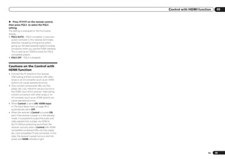
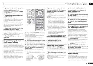
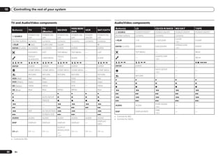
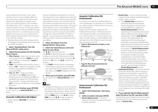
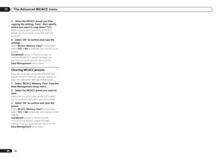
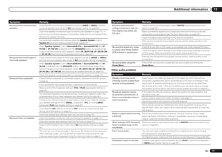
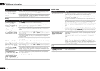
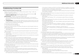
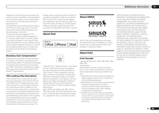
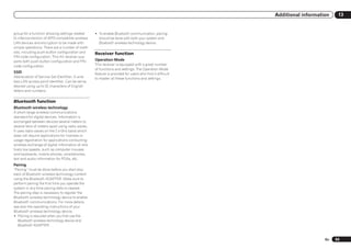
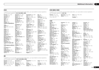
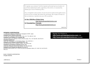
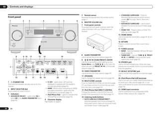
This plan replaces the left and right front height Front Bi-Amp
Determining the speakers’ FHR speakers shown in [A] with the left and right
application FHL
front wide speakers (FWL/FWR).
R It is not possible to produce sound simultane-
This unit permits you to build various surround R
ously from the front height or front wide speak-
systems, in accordance with the number of
L ers and the surround back speakers.
speakers you have. SW 2 L
C
SR This surround system produces a true-to-life SW 2
! Be sure to connect speakers to the front left SW 1 C
sound over a wider area. SW 1
and right channels (L and R).
! It is also possible to only connect one of the [C] 7.2 channel surround system & Speaker
surround back speakers (SB) or neither. SBR B connection
SL SR
! If you have two subwoofers, the second SBL ! Speaker System setting: Speaker B
subwoofer can be connected to the SL
SUBWOOFER 2 terminal. Connecting two
subwoofers increases the bass sound to
achieve more powerful sound reproduction. In A 7.2 ch surround system connects the left and
R [E] 5.2 channel surround system & ZONE 2
this case, the same sound is output from the right front speakers (L/R), the center speaker
connection (Multi Zone)
two subwoofers. (C), the left and right front height speakers L
! Speaker System setting: ZONE 2
Choose one from Plans [A] to [E] below. (FHL/FHR), the left and right surround speak- R
SW 2 With these connections you can simultaneously
ers (SL/SR), the left and right surround back C
SR L
SW 1 enjoy 5.2-channel surround sound in the main
speakers (SBL/SBR), and the subwoofers (SW 1/
Important zone with stereo playback on another compo-
SW 2).
! The Speaker System setting must be made if nent in ZONE 2. (The selection of input devices
It is not possible to produce sound simultane- SBR
you use any of the connections shown below SL is limited.)
ously from the front height or front wide speak- SBL Speaker B
other than [A] (see Speaker system setting on ers and the surround back speakers.
page 69 ). This surround system produces a more true-to- Main zone
! Sound does not come through simultaneously life sound from above.
R
from the front height, front wide, speaker B With these connections you can simultaneously
[B] 7.2 channel surround system (Front L
and surround back speakers. Output speakers enjoy 5.2-channel surround sound in the main
are different depending on the input signal or wide) zone with stereo playback of the same sound
SW 2
listening mode. ! Speaker System setting: Normal(SB/FW) on the B speakers. The same connections also C
SW 1
allow for 7.2-channel surround sound in the
[A] 7.2 channel surround system (Front
main zone when not using the B speakers.
height)
[D] 5.2 channel surround system & Front SR
*Default setting R
! Speaker System setting: Normal(SB/FH) FWR Bi-amping connection (High quality SL Sub zone
L surround)
! Speaker System setting: Front Bi-Amp
SW 2 SR
C Bi-amping connection of the front speakers for R
SW 1
high sound quality with 5.2-channel surround L
FWL ZONE 2
sound.
SBR
SL
SBL
12 En](https://image.slidesharecdn.com/vsx-52operatinginstructions051911-111202034130-phpapp01/85/Vsx-52-operating-instructions051911-12-320.jpg)