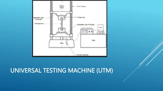
UNIT - II
DEFORMATION OF METALS
INTRODUCTION
No engineering material is perfectly rigid. When a material is
subjected to external load, it undergoes deformation. While
undergoing deformation, the particles of the material exert a
resisting force. When this resisting force equals applied load,
the equilibrium condition exists hence deformation stops.
This internal resistance is called the stress.
Classification of force system
 According to the applied load, the force system is classified
as follows:
 Tensile force system
 Compressive force system
 Shear force system
Definition of load, stress and strain
 Load
The system of external forces acting on a body or structure is known as load.
 Stress
The stress or intensity of stress at a section may be defined as the ratio of the
internal resistance or load acting on the section to the cross sectional area of that
section.
Stress, ƒ = Internal resistance = Load = P
Area of cross section Area A
 The unit of stress is N/mm2. The latest S.I unit for stress is Pascal.
 Strain
Strain may be defined as the ratio between the deformation produced in a
body due to the applied load and the original dimension.
Composite bars
A composite bar may be defined as a bar made of two or
more different materials joined together in such a way that
the system elongates or contracts as a whole equally when
subjected to axial pull or push
l
P
2
1
STRESS STRAIN CURVE
MECHANICAL TESTING OF MATERIALS
Tensile test of mild steel on UTM
 Tensile tests are used to determine the mechanical behaviour of
materials under axial tensile load. It is carried out in Universal Testing
Machine (UTM)
UNIVERSAL TESTING MACHINE (UTM)
PROCEDURE FOR TENSILE TEST
 Measure the total length, gauge length and the diameter of the specimen.
 Fix the specimen in-between the upper and middle cross heads using the
gripping devices.
 Apply the axial tensile load on the specimen gradually.
 Record the extensometer readings at a constant load increment.
 Record the yield point, ultimate point and point of failure of the specimen.
 Measure the final gauge length and the diameter at the neck.
Overall Lenght
Grip section Gauge Length
Initial Dia.
THANK YOU
THE END

UNIT - II.pptx............................

  • 1.
  • 2.
    INTRODUCTION No engineering materialis perfectly rigid. When a material is subjected to external load, it undergoes deformation. While undergoing deformation, the particles of the material exert a resisting force. When this resisting force equals applied load, the equilibrium condition exists hence deformation stops. This internal resistance is called the stress.
  • 3.
    Classification of forcesystem  According to the applied load, the force system is classified as follows:  Tensile force system  Compressive force system  Shear force system
  • 4.
    Definition of load,stress and strain  Load The system of external forces acting on a body or structure is known as load.  Stress The stress or intensity of stress at a section may be defined as the ratio of the internal resistance or load acting on the section to the cross sectional area of that section. Stress, ƒ = Internal resistance = Load = P Area of cross section Area A  The unit of stress is N/mm2. The latest S.I unit for stress is Pascal.  Strain Strain may be defined as the ratio between the deformation produced in a body due to the applied load and the original dimension.
  • 5.
    Composite bars A compositebar may be defined as a bar made of two or more different materials joined together in such a way that the system elongates or contracts as a whole equally when subjected to axial pull or push l P 2 1
  • 6.
  • 7.
    MECHANICAL TESTING OFMATERIALS Tensile test of mild steel on UTM  Tensile tests are used to determine the mechanical behaviour of materials under axial tensile load. It is carried out in Universal Testing Machine (UTM)
  • 8.
  • 9.
    PROCEDURE FOR TENSILETEST  Measure the total length, gauge length and the diameter of the specimen.  Fix the specimen in-between the upper and middle cross heads using the gripping devices.  Apply the axial tensile load on the specimen gradually.  Record the extensometer readings at a constant load increment.  Record the yield point, ultimate point and point of failure of the specimen.  Measure the final gauge length and the diameter at the neck. Overall Lenght Grip section Gauge Length Initial Dia.
  • 10.