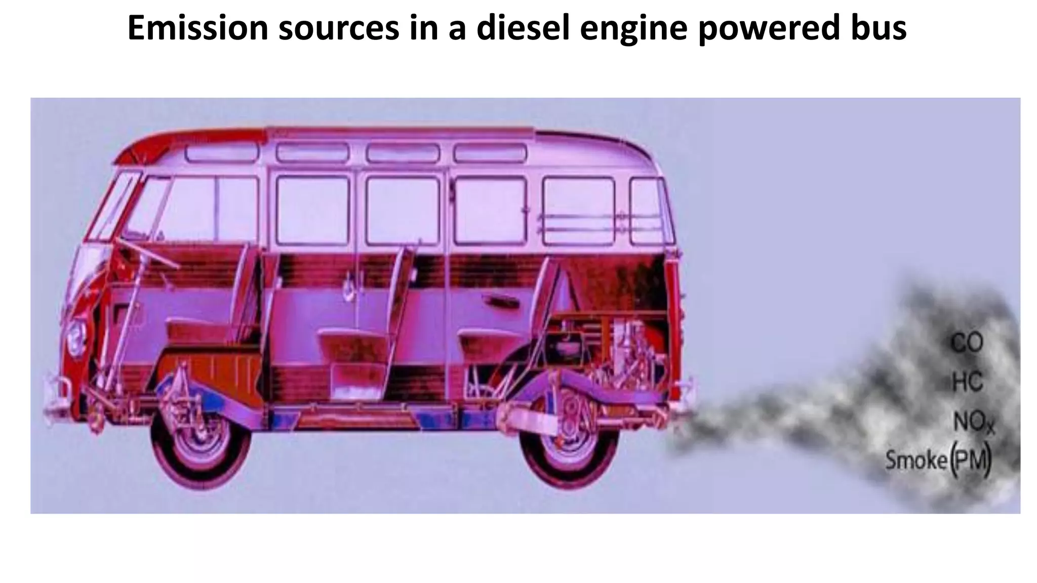
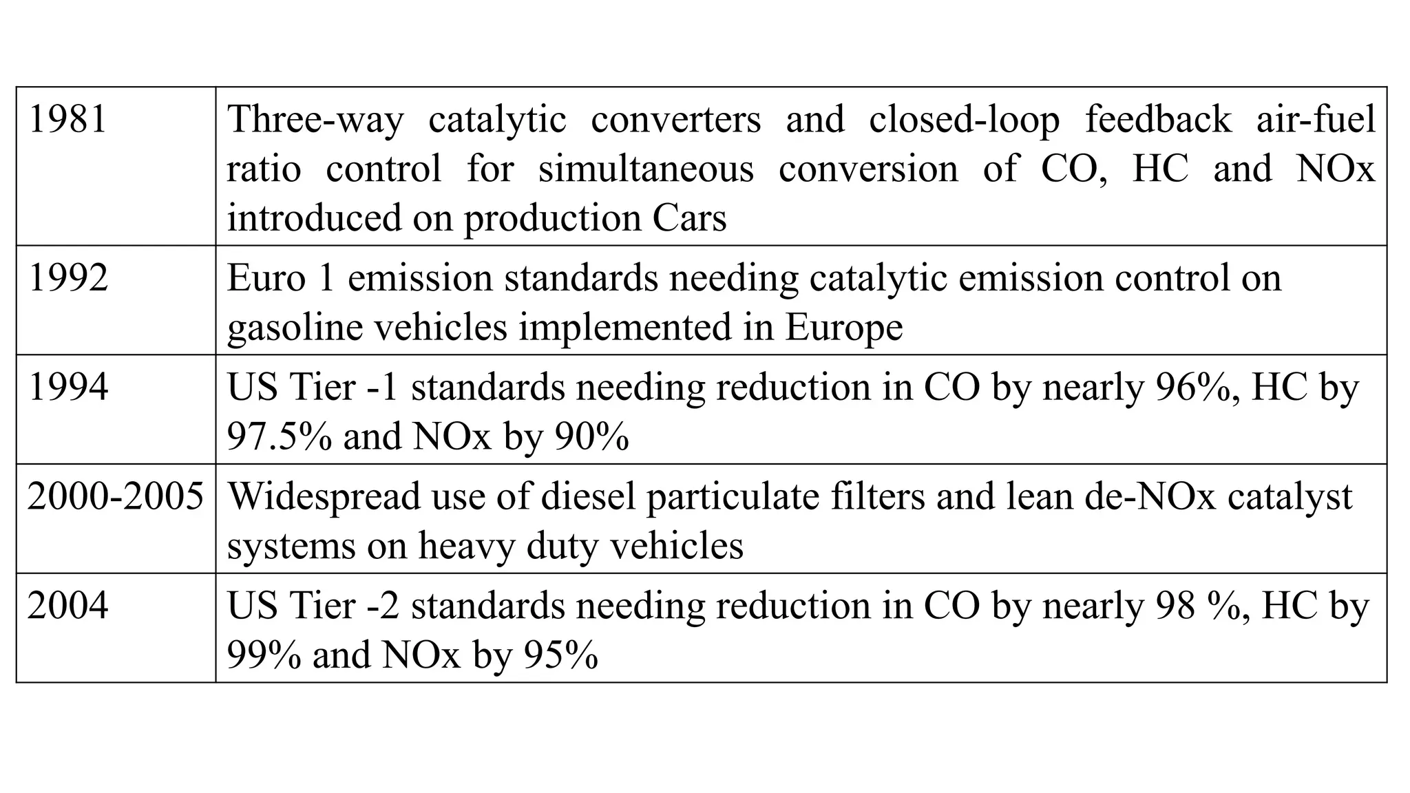
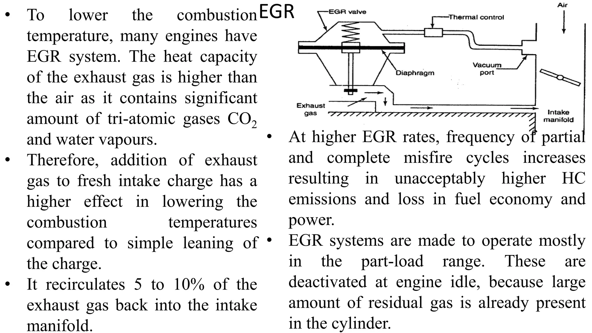
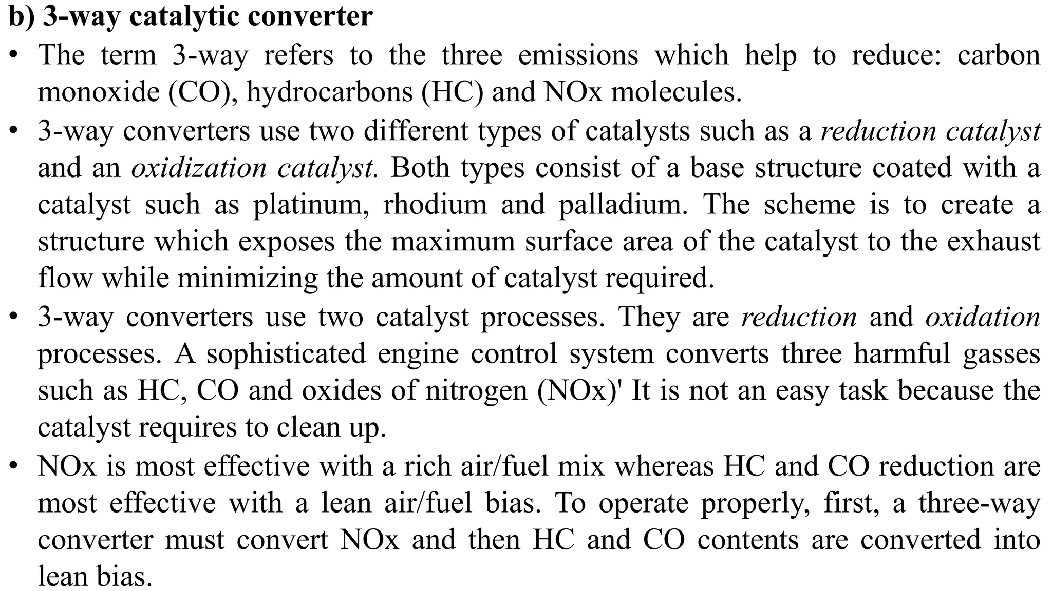
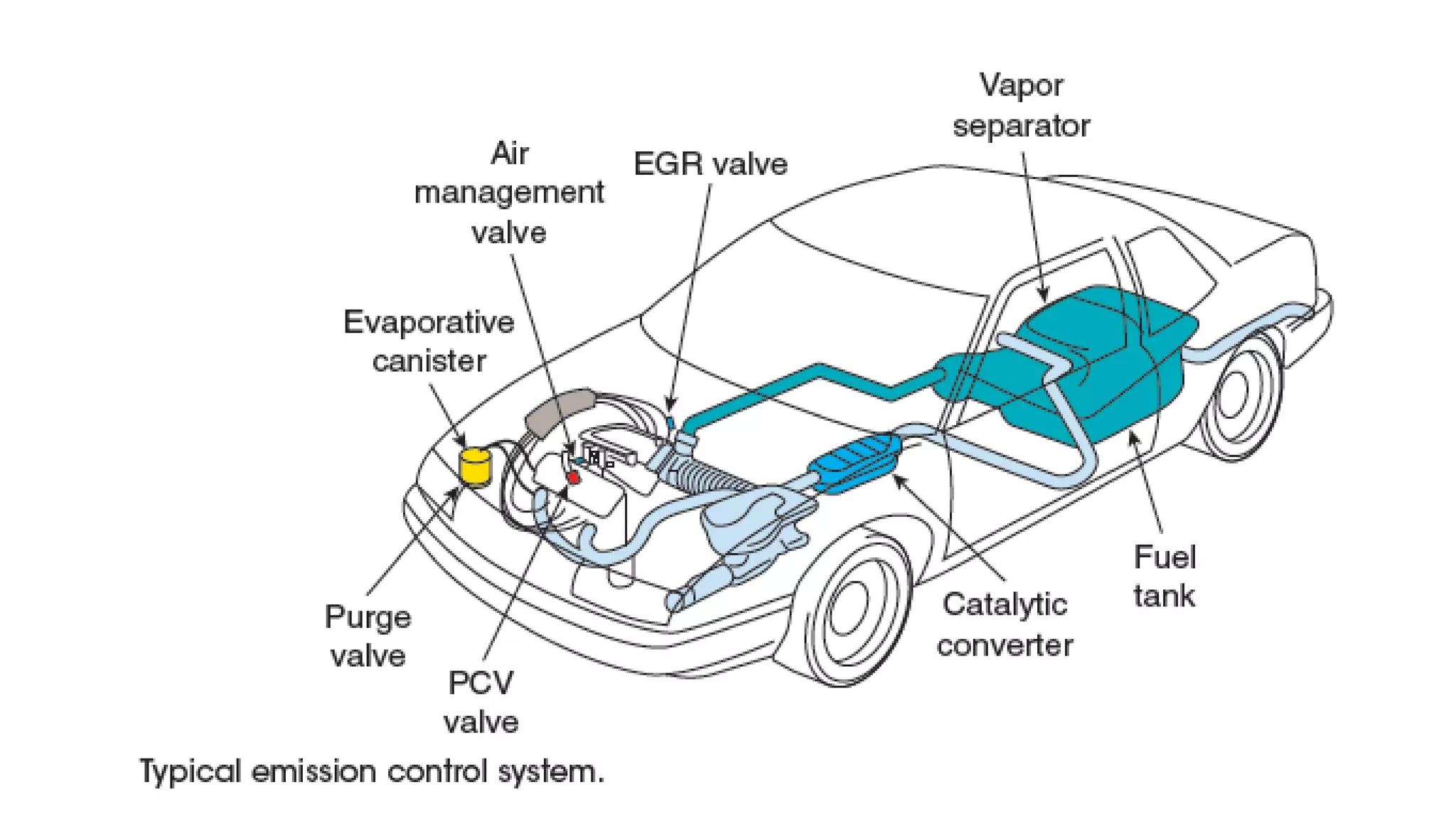
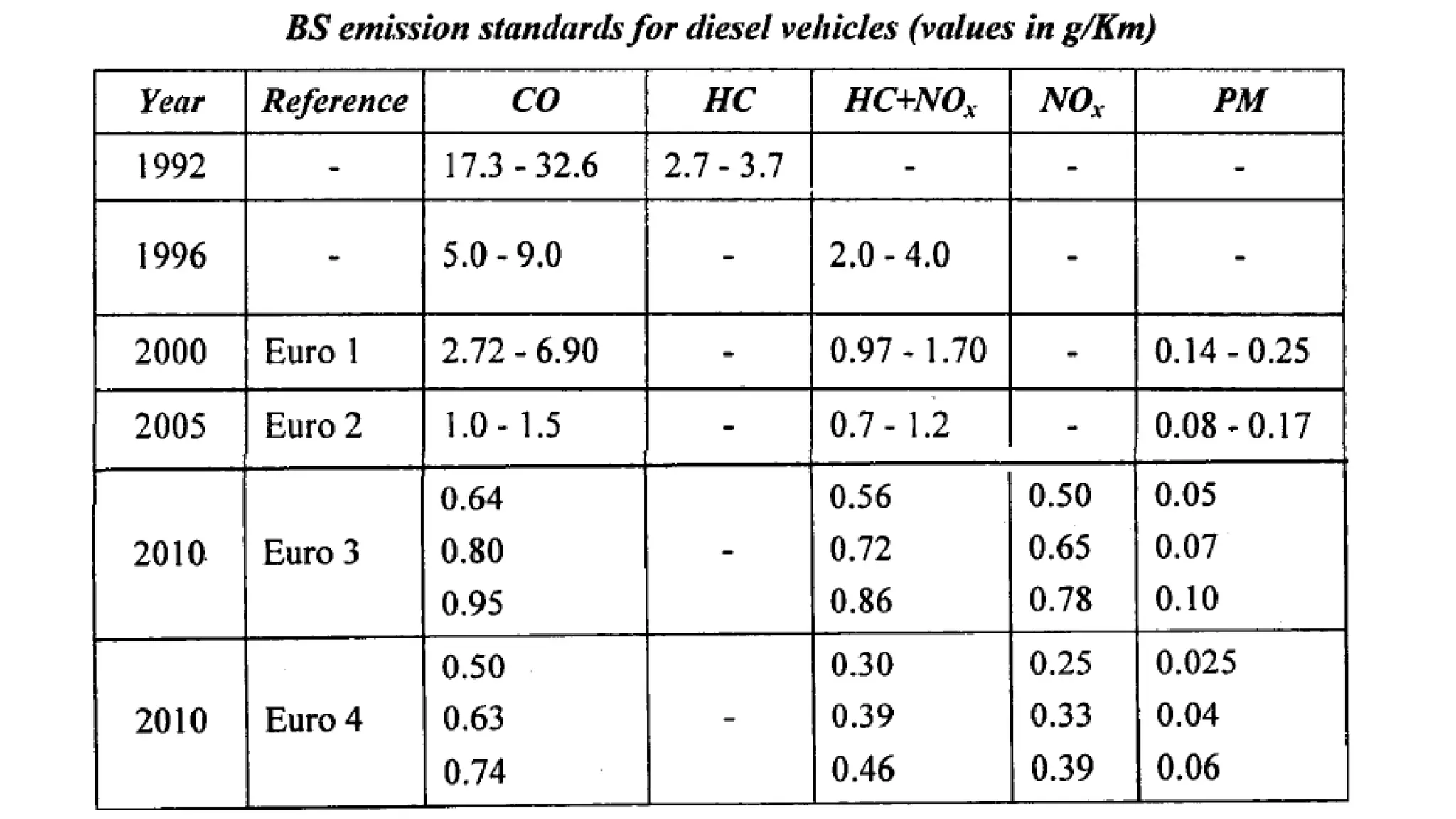
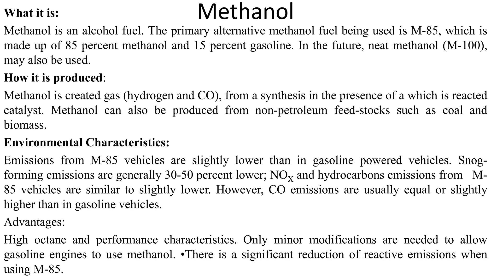
AUTOMOBILE ENGINEERING
UNIT 6
ENGINE EMISSION CONTROL: Introduction – types of pollutants, mechanism of
formation, concentration measurement, methods of controlling-engine modification,
exhaust gas treatment-thermal and catalytic converters-use of alternative fuels for
emission control – National and International pollution standards
ENGINE SERVICE: Introduction, service details of engine cylinder head, valves and
valve mechanism, piston-connecting rod assembly, cylinder block, crank shaft and
main bearings, engine reassembly-precautions.
PART I
ENGINE EMISSION CONTROL
Automotive Emissions
• Sources of emissions
 Exhaust pipe (60), crank-case(20), and vapors(20)
• CO = Carbon monoxide, HC = Unburned hydrocarbons, NOx = Nitrogen oxides mainly
mixture of NO and NO2 , PM = Particulate matter
• Other engine emissions include aldehydes such as formaldehyde and acetaldehyde
primarily from the alcohol fuelled engines, benzene and polyaromatic hydrocarbons
(PAH).
• Hydrocarbon sources
• Blowby gases
 Raw gas in exhaust
 Insufficient compression
 Inadequate ignition spark
• Carbon monoxide emissions
 Result when gasoline not completely burned
• Oxides of nitrogen
Produced when combustion temperatures are too high
• Particulates
 Are airborne microscopic particles
• Carbon dioxide and oxygen
 Used to diagnose combustion problems
 Carbon dioxide is a greenhouse gas
SI Engines CO, HC and NOx
CI Engines CO, HC, NOx and PM
Emission sources in a gasoline fuelled car
Emission sources in a diesel engine powered bus
SI engine vehicles without emission control have three sources of
emissions
Exhaust
emissions
Almost all of 100% of NOx and CO, and 60% of HC are
emitted through the engine exhaust or vehicle tailpipe
Crankcase
emissions
About 20% of HC are emitted via crankcase blow by
gases
Evaporative
Emissions
Fuel evaporation from tank, fuel system, carburettor and
permeation through fuel lines constitute another 20% of
total HC
CI engines on the other hand release all of harmful emissions into
atmosphere through its exhaust gases
Adverse Health Effects of IC Engine Generated Air Pollutants
Pollutants Short-term health effects Long-term health effects
Carbon
monoxide
Headache, shortness of
breath, dizziness, impaired
judgment, lack of motor
coordination
Effects on brain and central nervous system,
nausea, vomiting, cardiac and pulmonary
functional changes, loss of consciousness and
death
Nitrogen
dioxide
Soreness, coughing, chest
discomfort, eye irritation
Development of cyanosis especially at lips,
fingers and toes, adverse changes in cell
structure of lung wall
Oxidants Difficulty in breathing, chest
tightness, eye irritation
Impaired lung function, increased susceptibility
to respiratory function
Sulfates Increased asthma attacks Reduced lung function when oxidants are
present
TSP/Respirable
Suspended
particulate
Increased susceptibility to
other pollutants
Many constituents especially poly-organic
matter are toxic and carcinogenic, contribute to
silicosis, brown lung
Engine Emission Control – A Historical Perspective
Year Event and Milestone
1952 Prof A. J. Haagen- Smit of Univ. of California demonstrated that the
photochemical reactions between unburned hydrocarbons (HC) and
nitrogen oxides (NOx) are responsible for smog (brown haze) observed in
Los-Angeles basin
1965 The first vehicle exhaust emissions standards were set in California, USA
1968 The exhaust emission standards set for the first time throughout the USA
1970 Vehicle emission standards set in European countries
1974 Exhaust catalytic converters for oxidation of carbon monoxide (CO) and
HC were needed in the US for meeting emission targets. Phasing-out of
tetra ethyl lead (TEL), the antiknock additive from gasoline begins to
ensure acceptable life of the catalytic converters
1981 Three-way catalytic converters and closed-loop feedback air-fuel
ratio control for simultaneous conversion of CO, HC and NOx
introduced on production Cars
1992 Euro 1 emission standards needing catalytic emission control on
gasoline vehicles implemented in Europe
1994 US Tier -1 standards needing reduction in CO by nearly 96%, HC by
97.5% and NOx by 90%
2000-2005 Widespread use of diesel particulate filters and lean de-NOx catalyst
systems on heavy duty vehicles
2004 US Tier -2 standards needing reduction in CO by nearly 98 %, HC by
99% and NOx by 95%
Typical Exhaust Emission Concentrations
• SI Engine (Gasoline fuelled)
Depending upon engine operating conditions without catalytic control engine out
emissions range :
CO 0.2 to 5% by volume (v/v)
HC 300 to 6000 ppmc1, v/v
NOx 50 to 2000 ppm, v/v
*ppmc1= parts per million as methane measured by Flame Ionization
Analyzer/Detector(FIA or FID)
CO emissions are high under engine idling and full load operation when engine is
operating on fuel rich mixtures. HC emissions are high under idling, during engine
warm-up and light load operation, acceleration and deceleration.
NOx are maximum under full engine load conditions.
• CI (Diesel) Engines
Diesel engines usually operate with more than 30% excess air band the emissions
are accordingly influenced.
CO 0.03 to 0.1%, v/v
HC 20 to 500 ppmc1
NOX 100 to 2000 ppm
PM 0.02 to 0.2 g/m3
(0.2 to 0.5% of fuel consumption by mass)
Emission Formation in SI Engines
NOx and CO are formed in the
burned gases in the cylinder.
Unburned HC emissions originate
when fuel escapes combustion due to
several processes such as flame
quenching in narrow passages present
in the combustion chamber and
incomplete oxidation of fuel that is
trapped or absorbed in oil film or
deposits
• NOx is formed by oxidation of molecular nitrogen. During combustion at high
flame temperatures, nitrogen and oxygen molecules in the inducted air
breakdown into atomic species which react to form NO. Some NO2 is also
formed and NO and NO2 together are called as NOx.
• CO results from incomplete oxidation of fuel carbon when insufficient oxygen
is available to completely oxidize the fuel. CO rises steeply as the air-fuel (A/F)
ratio is decreased below the stoichiometric A/F ratio.
• HC originates from the fuel escaping combustion primarily due to flame
quenching in crevices and on cold chamber walls, fuel vapour absorption in the
oil layer on the cylinder and in combustion chamber deposits, and presence of
liquid fuel in the cylinder during cold start
Nitric oxide emissions are
maximum at slightly (5-10 %)
leaner than stoichiometric
mixture due to combination of
availability of excess oxygen and
high combustion temperatures at
this point.
Carbon monoxide and HC
emissions reduce with increase
in the air-fuel ratio as more
oxygen gets available for
combustion.
Emission Formation in CI Engines
• Schematic of a diesel injection spray is shown in Fig. A fully developed diesel spray may be
considered to consist of three distinct regions based on the variations in fuel-air equivalence
ratio φ, across the cross section of the spray as seen radially outwards from the centreline of
spray.
• A fuel rich core where fuel-air equivalence ratio is richer than the rich flammability limits i.e.,
φ ˃ φR
• Flammable region in which φ lies within the rich and lean flammability limits, i.e., φR ˃ φ ˃ φL
• A lean flame-out region (LFOR) where φ is lower than lean flammability limits and extends up
to the spray boundary i.e., φL ˃ φ ˃ 0
• Pollutant formation is strongly dependent on the fuel-air ratio distribution
in the spray:
• NO is formed in the high temperature burned gases in the flammable region.
Maximum burned gas temperatures result close to stoichiometric air-fuel ratio
and these contribute maximum to NO formation.
• CO is formed in fuel rich mixtures in the flammable region.
• Soot forms in fuel-rich spray core where fuel vapour is heated by the hot burned
gases .
• Unburned HC and oxygenated hydrocarbons like aldehydes originate in the
region where due to excessive dilution with air the mixture is too lean at the
spray boundaries. In excessive lean mixtures combustion process either fails to
begin or does not reach completion. Towards the end of combustion, fuel in the
nozzle sac and orifices gets vaporized, enters the combustion chamber and
contributes to HC emissions.
Measurement techniques
used to measure pollutants concentration
Non Dispersive Infrared Analyser (NDIR): detectors are the industry standard
method of measuring the concentration of carbon oxides (CO & CO2)
Absorption bands of common gases: The flame ionisation detector (FID) is the
industry standard method of measuring hydrocarbon (HC) concentration
Chemi-luminescence detector (CLD): It is the industry standard method of
measuring nitric oxide (NO) concentration
Pollution Control
The pollution may be controlled by the following two ways.
I. The formation of pollutants is prevented as far as possible.
2. The pollutants are destroyed after they are formed.
Control of hydrocarbon:
Formation of hydrocarbon may be reduced by the following methods.
1. Reducing the compression ratio.
2. Changing the design of combustion chamber.
3. Changing the design of piston.
4. By supplying lean mixture.
5. By maintaining of piston and piston ring.
Destroying the hydrocarbon may be done by the following methods.
I. By supplying air to the inlet manifold., 2. By using after burner, 3. By using
catalytic converter.
Control of CO and NOx:
Methods of reducing CO are as follows.
1. By using closed loop control.
2. By supplying lean mixture.
3. By providing suitable overlap of valves.
Methods of destroying CO are given below.
1. By using reactor in the exhaust manifold.
2. By using after burner.
3. By using catalyst converter.
Control of oxides of nitrogen:
Methods of reducing oxides of nitrogen are listed below.
1. By supplying the exhaust again to the inlet manifold.
2. By spraying water in the inlet manifold to add moisture to the mixture.
3. By using catalyst converter in the exhaust, the oxides of nitrogen can be
Evaporative Emission Control for SI engine
• Vapour goes to the top of the separator where the liquid petrol is separated and it
is returned to the tank. A vent valve is provided for venteing the fuel vapour to
the canister.
• A canister containing activated charcoal is used to store the fuel vapour. The
canister adsorbs the vapour and stores it. "Adsorption" refers to the process of
trapping of the petrol vapour by the activated charcoal particles packed inside
the canister. Due to the adsorption process, hydrocarbons are left in the canister
and the, air leaves-to the atmosphere.
• The evaporative emission control
system consists of a device to
store fuel vapour produced in the
fuel system due to evaporation.
• A vapour-liquid separator is
provided at the top of a fuel tank.
EGR
• To lower the combustion
temperature, many engines have
EGR system. The heat capacity
of the exhaust gas is higher than
the air as it contains significant
amount of tri-atomic gases CO2
and water vapours.
• Therefore, addition of exhaust
gas to fresh intake charge has a
higher effect in lowering the
combustion temperatures
compared to simple leaning of
the charge.
• It recirculates 5 to 10% of the
exhaust gas back into the intake
manifold.
• At higher EGR rates, frequency of partial
and complete misfire cycles increases
resulting in unacceptably higher HC
emissions and loss in fuel economy and
power.
• EGR systems are made to operate mostly
in the part-load range. These are
deactivated at engine idle, because large
amount of residual gas is already present
in the cylinder.
Crankcase Emission Control System
• A small amount of charge in the cylinder leaks past piston rings into crankcase
of the reciprocating engines.
• A significant part of charge stored in the piston- ring-cylinder gap leaks into the
crankcase. These gases are known as 'crankcase blow-by' and their flow rate
increases as the engine is worn out and the piston-cylinder clearances and ring
gaps increase.
• In the homogeneous charge engines, the crankcase blow by gas is high in HC
concentration. Only a small fraction of the gas stored in the ring crevices and
hence blow-by gases may consist of partially burnt mixture.
• This source contributes about 20% of total hydrocarbons emitted by an
uncontrolled car.
• For control of crankcase emissions, the blow-by gases are recycled back to the
engine assisted by a positive pressure drop between the crankcase and intake
manifold.
Engine Emission Control by Catalytic Converter
• The term catalytic converter covers the stainless steel box mounted in the
exhaust system. The catalyst is inside the cover which is a ceramic or metallic
base with an active coating incorporating alumina, ceria and other oxides and
combinations of precious metals such as platinum, palladium and rhodium.
• The catalytic converter converts the pollutants such as HC, CO and NO2 into
harmless gases. It is placed between exhaust manifold and silencer.
• The inside of the catalytic converter is a honeycomb set of passageways or small
ceramic beads coated with catalysts. A chemical reaction takes place to make the
pollutants less harmful.
• There are many passages for the exhaust gases to flow and allow for the
maximum amount of surface area for the hot gases to pass. There are two main
types of structures used in catalytic converters such as honeycomb and ceramic
beads. Most cars today use a honeycomb structure. Catalytic converters can
either be a two-way or three-way type.
a) Two-way or oxidation catalytic converter
Early converters, called "two-way" (or oxidation) catalytic converter converts
harmful carbon monoxide (CO) and hydrocarbons (HC) produced by relatively
inefficient, low compression engines to harmless carbon dioxide (CO2) and water
vapor (H2O) with the assistance of a precious-metallic catalyst. But these
converters have little effect on nitrogen oxides (NOx) and particulate matter. Two-
way converters are most effective when used with engines that have a lean air/fuel
mix because this condition provides ample oxygen to burn pollutants.
b) 3-way catalytic converter
• The term 3-way refers to the three emissions which help to reduce: carbon
monoxide (CO), hydrocarbons (HC) and NOx molecules.
• 3-way converters use two different types of catalysts such as a reduction catalyst
and an oxidization catalyst. Both types consist of a base structure coated with a
catalyst such as platinum, rhodium and palladium. The scheme is to create a
structure which exposes the maximum surface area of the catalyst to the exhaust
flow while minimizing the amount of catalyst required.
• 3-way converters use two catalyst processes. They are reduction and oxidation
processes. A sophisticated engine control system converts three harmful gasses
such as HC, CO and oxides of nitrogen (NOx)' It is not an easy task because the
catalyst requires to clean up.
• NOx is most effective with a rich air/fuel mix whereas HC and CO reduction are
most effective with a lean air/fuel bias. To operate properly, first, a three-way
converter must convert NOx and then HC and CO contents are converted into
lean bias.
EMISSION STANDARDS
ALTERNATIVE FUELS
Alternative fuels include : Methanol and ethanol (Alcohol
fuels) Natural gas (compressed or liquefied) Liquefied
petroleum gas Hydrogen , Biodiesel etc.
Methanol
What it is:
Methanol is an alcohol fuel. The primary alternative methanol fuel being used is M-85, which is
made up of 85 percent methanol and 15 percent gasoline. In the future, neat methanol (M-100),
may also be used.
How it is produced:
Methanol is created gas (hydrogen and CO), from a synthesis in the presence of a which is reacted
catalyst. Methanol can also be produced from non-petroleum feed-stocks such as coal and
biomass.
Environmental Characteristics:
Emissions from M-85 vehicles are slightly lower than in gasoline powered vehicles. Snog-
forming emissions are generally 30-50 percent lower; NOX and hydrocarbons emissions from M-
85 vehicles are similar to slightly lower. However, CO emissions are usually equal or slightly
higher than in gasoline vehicles.
Advantages:
High octane and performance characteristics. Only minor modifications are needed to allow
gasoline engines to use methanol. •There is a significant reduction of reactive emissions when
using M-85.
Ethanol
What it is:
• It's a cheap non-petroleum based fuel. As with methanol, E-85 is the primary ethanol
alternative fuel. The use of ethanol in vehicles is not a new innovation. In the 1880s, Henry
Ford built one of his first automobiles to run on ethanol.
How is it produced:
• It can be produced by fermentation of vegetables and plant materials. In India, its main source
is molasses a byproduct of sugarcane. Its done in three stages
1. Extraction of juice from sugarcane 2. Fermentation of the juice 3. Distillation
Environmental Characteristics: It has approximately 30-50% fewer smog forming emissions
than a gasoline vehicle. Air toxics are also reduced by about 50 percent when compared to
gasoline. As with all internal combustion engines, vehicles using ethanol emit minor amounts of
aldehydes. This is resolved by installing advanced catalytic converters on the vehicles. Major
problem with ethanol is the corrosion. Ethanol driven vehicles require lines, hoses and valves
to be resistant to the corrosion that alcohol can induce. Alcohol corrodes lead-plated fuel tanks;
magnesium, copper, lead, zinc, and aluminum parts; and some synthetic gaskets.
Natural Gas LNG & CNG
What it is:
Natural gas is a mixture of hydrocarbons - mainly methane (CH4). It can be stored on a vehicle
either in a compressed gaseous state (CNG) or in a liquefied state (LNG).
How it is produced:
Natural gas is primarily extracted from gas wells or in conjunction with crude oil production. it
can also be produced as a "by-product" of landfill operations.
Environmental Characteristics:
Natural gas has low CO emissions, virtually no PM (particulate matter) reduced volatile organic
emissions, and compounds. Per unit of energy, natural gas contains less carbon than any other
fossil fuel, leading to lower CO2 emissions per vehicle mile traveled.
Advantages
1. Its cheap 2. It's Engine- Friendly 3. It's safe 4. There is lot of it in India. 5. It's clean, easy to
trap and odorless.
Disadvantages 1. The storage cylinder takes a lot of space. 2. CNG gas stations are not widely
available in India.
Liquefied Petroleum Gas - LPG
What it is:
Liquefied petroleum gas (LPG) consists of various hydrocarbons, mainly propane, propylene,
butane, and butylene in various mixtures. The main constituent, in most of the cases , is
propane.
How it is produced:
LPG is a byproduct of natural gas processing and petroleum refining.
Environmental Characteristics:
The LPG run vehicles have lower emission of reactive hydrocarbons (about one-third less),
NOX (20 percent less), and CO (60 percent less) than gasoline vehicles.
Advantages
l. lts cost is 60% of petrol with 90% of its mile age.
2.Has a higher octane number and burns more efficiently.
3.LPG has many of the storage and transportation advantages of liquids, along with the fuel
advantages of gases.
4. Saves on the maintenance costs.
Hydrogen (H2)
What it is:
Hydrogen gas (H2)
How it is produced:
Hydrogen can be produced from a number of different sources, including natural gas, water,
methanol etc. Two methods are generally used to produce hydrogen: (1) Electrolysis (2) Synthesis
gas production from steam reforming or partial oxidation.
Environmental Characteristics:
When combusted (oxidized), only water vapor is produced. When burned in an internal combustion
engine, small amounts of nitrogen oxides and small amounts of unburned hydrocarbons and carbon
monoxide are produced, due to the use of engine lubricants.
Advantages
'Hydrogen-air mixture burns nearly 10 times faster than gasoline- air mixture. 'Hydrogen has high
self-ignition temperature but requires very little energy to ignite it. Clean exhaust, produces no CO2.
a fuel it is very efficient as there are no losses associated with throttling.
Disadvantages There is danger of back fire and induction ignition. Though low in exhaust , it
produces toxic NOx. difficult to handle and store, requiring high capital and running cost.
Biodiesel
What it is:
Biodiesel is a fuel made primarily from the oils and fats of plants. Although, it can be used as a
straight replacement to diesel, the blend of biodiesel to diesel can be as low as 20% biodiesel, 80%
diesel.
How it is produced:
Biodiesel can be produced through a transesterfication process, forming fatty esters. One of the
byproducts of production is glycerol, which can then be sold as an independent product.
Biodiesel Environmental Characteristics:
Biodiesel has no aromatic content and only trace amounts of sulfur. It has lower CO, polycyclic
aromatic soot and hydrocarbons than conventional diesel. With adjustments in the injection engine
timing, it is possible to reduce the NOX emissions.
Advantages
Low Emissions
It is biodegradable and non-toxic
Low cost
High Cetane Number
PART II
ENGINE SERVICE
Why engine service is required
• Major diagnosis areas
– Oil consumption
– Engine noises
– Oil pressure problems
– Cooling system problems
• Causes of engine problems
– Normal wear
– Lack of maintenance
– Previous work
– Problems in other areas
Diagnosing Problems Before a Repair
• Diagnose engine before disassembly
– Determine repair is necessary
– Determine exact location while engine running
• Discuss problem with vehicle’s owner
– Driving habits or lack of maintenance may be the cause
Oil Consumption
• Oil lost is through external leakage or internal oil consumption
– Internal consumption: spotted by oily coating on inside of exhaust
pipe or blue smoke
• Overly rich air-fuel mixture causes black soot on exhaust pipe and black
smoke
• Normal oil consumption
– Depends on size of engine, vehicle weight, shape, etc.
Causes of Oil Consumption
• Bad valve guides or seals
– Smoke visible from exhaust during deceleration
• Worn compression rings
– Frequent cause: poor maintenance
• Increased consumption after a valve job
– Consider entire engine
• Excessive rod bearing clearance
– Engines with high mileage
• Vacuum modulator
– Older automatic transmissions
Causes of Oil Consumption (cont'd.)
• Incorrect oil level
– Incorrect dipstick size causes overfilling
• Plugged cylinder head drainback holes
– Poor maintenance
• Leaking V-type intake manifold gasket
– Difficult problem to find
• Crankcase pressure
– Plugged PCV valve
Testing for Oil Leaks
• Oil can leak past gaskets and seals
– Rear main bearing seal leak
• Oil on engine side of flywheel or torque converter
– Front transmission seal leak
• Oil on transmission side of torque converter
• Black light testing
– Add one ounce of florescent liquid to oil
– Drive the car
– Use a black light and a mirror to find leaks
Engine Performance and Compression Loss
• Compression loss causes
– Blown head gasket
– Burned valves
– Broken piston rings
Engine Noises
• Determine noise location before disassembly
– Noises can be transmitted from their origins to other locations
• Difficult to isolate
• Accessories can cause noises
– Inspect alternators, smog pumps, air-conditioning compressors, and
coolant pumps
– Belts a common source of noise
– Fan clutch on coolant pump can sound serious
• Difficult to locate
Engine Knocks
• Crankshaft noises: generally deeper in pitch
– Front main bearing knock
– Thrust bearing knock
– Rod knock
– Related noises (e.g., loose flywheel, torque converter, and vibration
damper)
– Bent oil pan
– Rod side clearance
Engine Knocks (cont’d.)
• Piston noises
– Cracked pistons
– Piston slap
– Excess piston pin clearance
– Other piston sounds
Engine Knocks (cont’d.)
• Valve train noises: loud ticking sound
– Sticking valve
– Worn or flat cam lobe
– Timing components
• Lifter noises: occur when engine is first started
– Intermittent noise at idle or low speed
– Noise at idle that goes away at higher speeds
– Quiet at idle but noisy at high speed
Engine Knocks (cont’d.)
• Lifter noise at all engine speeds
– Dirt or varnish buildup
– Worn parts or insufficient oil supply
– Oil is too thin or pressure is too low
• Spark knock noise
– Several causes
– Excessive carbon buildup
• Broken motor mount
– Check for engine lift when transmission is in forward and reverse
ranges with brakes applied
Oil Pressure Problems
• Low oil causes major engine damage
– Lower main bearing wear: oil pressure permanently low at idle
• Low oil pressure
– Faulty oil pressure sending unit
• High oil pressure
– Stuck pressure relief valve
– Severe blockage in oil gallery
• Oil analyzed in a lab
– Identifies mechanical problems
Cooling System Problems
• Neglected cooling system
– Results in expensive engine damage
• Plugged or corroded radiator
– Cannot conduct heat away from engine
– Overheats at freeway speeds
• Water jackets develop buildup of minerals and scale
– Prevents heat transfer
– Material flakes off and plugs radiator
Internal Engine Leakage
• Locations of internal leaks
– Water crossover passage of intake manifold
– Threaded plugs beneath valve covers
– Combustion chamber
– Cracked cylinder block
• Diagnosed using:
– Block tester, pressure tester, or infrared analyzer
• Cross fluid contamination
– Water leaking into crankcase contaminates oil
Internal Engine Leakage (cont'd.)
• Internal oil to coolant leaks
– Leak between oil and water passageway causes pressurized oil to
leak into cooling system
• Spotted by installing pressure tester on radiator filler neck
– Leaking head gasket may not show up on a pressure test
• Block check tester or infrared exhaust analyzer checks for exhaust gas in
coolant
• Bubbles in coolant indicate a leak
Seized Engine
• Starter motor will not crank the engine
– Engine cannot be cranked by hand
• Frozen accessory can prevent engine from cranking
– Drive belt can become so hot it melts
• Coolant thermoplastic seizure
– Coolant mixes with engine oil
• Hydrolock
– Both cylinder valves are closed
Electronic Failures/Engine Damage
• Engine damage may be traced to electronic component
failures
– EGR valve becomes inoperative if its input sensor signals interrupted
– Electric cooling fan failure can be due to inoperative sensor
– Overly rich air-fuel mixture can cause oil dilution
• Always trace a problem to its root cause
Engine Performance
and Fuel Mixture Problems
• Emission control and fuel system malfunctions
– Mimic problems related to the engine
• Lean air-fuel mixture
– Increases heat in combustion chamber
• Results: detonation or burned internal engine parts
• Rich air-fuel mixture
– Causes oil wash
• Oil washed from cylinder walls
• Leaking fuel injectors also cause oil wash
ENGINE REMOVAL AND DISASSEMBLY
Objectives
• Label and organize parts prior to engine removal
• Remove an engine from a vehicle in a safe and methodical
manner
• Disassemble the engine following the correct procedures
• Keep parts organized for reassembly
• Inspect and interpret causes internal engine wear
Introduction
• Procedures must be followed carefully
– Parts must be removed and inspected in an orderly manner
• You cannot hurry
• Signs of wear can be clues
• Correct repair will prevent the problem from occurring again
– Be sure to consult the applicable repair manual
• Procedures differ
Engine Removal
• Important steps
– Disconnect battery cables
– Remove the hood
– Remove air cleaner
– Label all wires and vacuum lines
– Drain coolant and oil
– Remove the radiator
– Remove the distributor and spark plug wiring
– Remove the direct current (DC) generator
– Remove the heater hoses and ground strap
Engine Removal (cont'd.)
– Remove switches and sensors
– Remove the throttle linkage, cable, or wiring
– Mark accessory brackets and remove accessories
– Remove exhaust components
– Remove and plug the fuel line
– Determine whether to remove the transmission
– Separate the engine and transmission/transaxle
– Unbolt the engine mounts
Engine Removal (cont'd.)
– Remove the engine from the vehicle
– Remove transaxle (if necessary)
• Remove lower ball joints
– Have drain pan ready
• Disconnect speedometer cable, transmission shift linkage, and clutch cable
• Attach a sling to the engine and transaxle assembly
• Remove bolts
• Roll shop crane until the engine can be lowered safely
Engine Disassembly
• Important steps
– Remove clutch parts
– Remove hybrid armature (puller required)
– Mount engine to a stand
– Remove coolant pump
– Remove oil pan
– Remove valve covers
• Slip a knife blade between head and sheet metal valve cover
• Tap a curved, strong area with a rubber mallet
Engines with Pushrods
• Stud mounted rockers
– Loosen nuts on studs before disassembly and cleaning
– Turn rocker arms to the side to remove the pushrods
– After heads are cleaned they can be removed one at a time
– Keep pushrods in order
Engines with Pushrods (cont'd.)
• Shaft-mounted rockers
– Should be loosened slowly and evenly
– Remove the pushrods
– Pushrods can be pushed through holes made in a piece of cardboard
– Pushrods must be kept in order
Engines with Pushrods (cont'd.)
• Valve lifters
– Remove valve lifters
– Wipe oil off bottom of lifters
– Label with a felt marker
– Reused flat tappers must be used on original cam lobe
• Usually replaced
– Roller lifters are usually reusable
– Use chemical cleaner to soften varnish
Engines with Pushrods (cont'd.)
• Pushrod engine camshaft
– Some pushrod engines use bolt-on cam thrust plate
– Varnish may builds up on edges of cam journals
• Makes it difficult to remove the cam
• Vibration damper removal
– Most engines have a bolt that holds it on the crankshaft
• Some will slip off after the bolt is removed
– Others are pressed-fit
Overhead Cam Cylinder Head
Removal
• Important steps
– Position the number one piston at TDC and note the location of
timing marks
– Compare the sketch in the repair manual to the marks on the timing
belt
– Draw a sketch of the cam timing
– Remove timing cover
Overhead Cam Engines (cont'd.)
– Remove the cam drive assembly
• Pushrod engines
– Unbolt cam sprocket and slide or pry off the cam
– Remove the chain
– Reinstall sprocket and tighten one bolt finger tight
• Overhead cam engines
– Remove the chain or bolt tensioner
Overhead Cam Engines (cont'd.)
– Remove the cylinder heads
• Mark one of the cylinder heads “left” or “right” if there is more than one
• Be careful not to break a casting
– Inspect the head gasket
• Evidence of coolant or oil leakage
• Signs of detonation
Cylinder Block Disassembly
• Modern engines use premium piston rings
– Will not accommodate a worn cylinder bore
• Ridge causes
– Pressure of combustion forcing the piston ring against the cylinder
wall
– Lack of clean lubrication at the top of the cylinder
Cylinder Block Disassembly (cont'd.)
• Important steps
– Turn engine over and mark main caps and rod caps
– Main caps must be installed in one direction only
– Connecting rods and caps are mated to one another and must be
marked for identification
– Remove and inspect the piston and rod assembly
– Inspect the piston, rings, rod, and bearings
– Remove the crankshaft and inspect for wear
– Remove the camshaft
Cylinder Block Disassembly (cont'd.)
– Remove and label cam bearings
– Remove core plugs
– Clean engine parts
– Remove the crank sprocket or gear
– Finish diagnosis and repair of engine assembly
Service of Cylinder Head and Valvetrain
Objectives
• Disassemble a cylinder head in the correct manner
• Clean and inspect a cylinder head for cracks and warpage
• Diagnose cylinder head and valve train wear problems and determine the
correct repair procedure
• Understand machine shop repair processes for cylinder heads
• Reassemble a cylinder head
• Understand camshaft and cam drive service procedures
Introduction
• Valve job
– Cylinder head is removed for valve refinishing
• Leaking head gasket
– Removed for resurfacing and gasket replacement
• Timing chain or timing belt service
– Important maintenance procedures on today’s long-life engines
Head Disassembly and Carbon Removal
• Cylinder heads: easier to work on if clean
– OHC heads with removable cam caps: verify caps are correctly
numbered
• Removing valve springs: wear face protection
– Keep valves in order
– Measure and record valve stem and spring height
• Carbon removal
– Most OHC heads have oil galleries
– Carbon can be removed from necks of valves
Cylinder Head Inspection
• Cylinder heads sometimes warp
– Warped heads are resurfaced
• Clean head before checking for flatness
– Rock the straightedge so one edge of it rests against the opposite side
of the head
– A round, straight bar is also available for checking straightness
• Warpage
– Cast iron head warpage
– Aluminium head warpage
Resurfacing by Grinding,
Cutting, or Sanding
• Resurfacing methods
– Fly-cutting
– Grinding the head
• Correct surface finish is very important
– Multilayered steel (MLS) gaskets
• Require a very smooth surface finish
• Head resurfacing
– Can increase compression
Straightening Cylinder Heads
• Warped aluminum OHC heads
– Commonly straightened
– Several methods for straightening cylinder heads
• Best: heating oven
– Straighten the head prior to surfacing
• Combustion chamber volumes will remain equal
Crack Inspection
• Cracks are sometimes found:
– In combustion chambers
– Between adjacent combustion chambers
– On the valve spring side of the head
• Ways to detect cracks
– Magnetic crack inspection
– Dye penetrant
– Pressure testing
Crack Repair
• Cracks are sometimes repairable
– Only practical if the cost of a bare head is more than twice the cost of
the crack repair
• Cracks in iron heads
– Repaired with tapered, threaded plugs
• Welding heads
– Common method of repairing aluminum head cracks
Checking Valve Springs
• Springs are tested for:
– Tension
– Squareness
– Height
• Specifications are
available in the service
manual
Checking Valve Stems
• Valves wear: oil consumption results
– Measure the valve stem with a micrometer
Valve Guide Service
• Valve guides are checked for wear
– Wear in a bell mouth fashion
• Can result in oil consumption
• Valve seat has worn and is wider than usual
– Look for a worn valve guide as the cause
• Checking valve stem-to-guide clearance
– Split ball gauge and micrometer
– Dial indicator
Guide Repair
• Guides are repaired in several ways
– Worn integral guide bored out to accept a pressed-fit insert guide
– Worn insert guide pressed out and replaced with a new one
– Knurling
– Thinwall insert
Grinding Valves
• Valves are refinished on face angle using a valve grinder
– Stem tip is reground flat
– Grinding wheel is dressed with an industrial diamond
– Some machinists grind an interference angle
– Very little metal is removed from surface of the valve face
Grinding Valve Seats
• Valve guides must be refinished before refinishing valve seats
– Valve seats are refinished with a grinding stone or a seat cutter
• 45-degree seat angle that mates with valve face is machined until
seat area is clean and free of pits
• 60-degree angle in the bottom of the seat (i.e., throat angle) is cut
very lightly
– Head must be thoroughly cleaned of all grit before beginning
assembly
Checking Valve Stem Installed Height
• Seat and valve are reground
– Stem moves further into the cylinder head
• Results in increased valve stem tip height and valve spring
installed height
• After grinding the valve and seat
– Check installed height
– Shims may be installed under the springs when a head is reassembled
Solvent Testing the Valve and Seat
• After the valve and seat have been ground:
– Install the spark plugs in their holes
– Turn head over so combustion chamber faces up
– Place head on head stands and put it on a shelf in solvent tank
– Install valves in the ports
– Fill the combustion chambers with solvent and check for leaks
Reassembling the Head and Valve Guide Seal
Installation
• Clean head before reassembly
– Thoroughly clean the guides
– Lubricate all valve stems
• Valve guide seal installation
– Install guide seals before installing springs on all but O-ring seals
– Check instructions in gasket set regarding placement of seals
– Lubricate seals before installing them
– Positive seals: often supplied with a plastic sheath
Install the Valve and Spring Assembly
• Some springs have coils more closely spaced at one end than at the other
– End more tightly coiled IS positioned against the cylinder head
• Compress spring just enough to install keepers
– Inspect each keeper for wear
– Use grease to help hold keepers in place
• Newer engines may use bee hive-shaped springs
– One end of coils smaller in diameter
Pushrod Engine Rocker Arm Service
• Stud-mounted rocker arms
– Not serviceable
– Replaced when worn
• Cast rocker arms that are shaft-mounted
– Can be reground
• Thoroughly lubricate rocker arms
– Before installing
Inspect Pushrods and OHC Camshaft
• Inspect pushrod ends and surface of socket where it pivots on rocker
arm
– Look for pitting or other unusual wear
– Roll pushrods on a bench to see if they are bent
• Overhead camshafts often have oil galleries and holes drilled in cam
lobes for direct lubrication
– Small oil holes are prone to plugging
– Check that oil holes are clear before installing
Reassembling OHC Heads
• Important steps
– Reinstall camshaft in the head
– Check to see camshaft cap alignment bushings are installed and
positioned correctly
– Bucket-type OHC heads
• Lubricate buckets and install them in the head prior to installing the
cam
– Adjust the valve clearance before installing the head on the engine
– Valve lash must be enough to allow heat to dissipate from valve to
valve seat
Camshaft Service
• Camshaft is inspected for wear
– Comparison measurement is made by measuring each lobe
• Visual check of cam lobes for wear is standard
• Lobes on roller cams are polished to fine matte finish
– During engine break-in, the lifter burnishes the lobe to a smooth
mirror finish
Lifter Service and Cam and Lifter Break-in
• Hydraulic lifters fail for several reasons
– Dirt lodged in the check valve
– Oil pressure problem
– Varnish accumulates between plunger and body
• Hydraulic lifters are not rebuilt
– Relatively inexpensive
• Worn mechanical lifters can be reground
• Lubrication and break-in are critical
– Cam that survives the first half hour of use without wear should last
the life of the vehicle
Timing Chain and Belt Service
• Camshafts on modern engines
– Driven by belt and chain
• Some older engines used two gears between the crankshaft and
camshaft
Timing Belt Service
• Increased timing belt fabric wear causes
– Poor alignment
– Incorrect tension
– Worn sprockets
• Inspect condition
– Twist belt gently
• Belt life
– Affected by contact with foreign materials
Timing Belt Replacement
• Follow manufacturer's recommendations for belt replacement interval
– Most American cars are free-wheeling
– Most replacements take three- to four-hours
– Install new belt and adjust belt tension until snug
• Do not adjust timing belt tension on a hot engine
– Affix a sticker to fender that tells the mileage when timing belt service
was done
Timing Chain Service
• Excessive chain stretch
– Checked in different ways
• Long chains like those used on OHC engines always use chain
tensioners
• Ways to time the cam to the crank
– Some timing sprockets are properly timed when the marks face each
other
– Some require a certain number of chain links between marks
– Some have colored links that must be aligned
Service of Piston, Piston Rings, Connecting
Rod, and Engine Balancing
Objectives
• Analyze wear and damage to the piston, piston rings, and
connecting rod
• Select and perform the most appropriate repairs to the piston,
piston rings, and connecting rod
• Explain the theory of engine balancing
Introduction
• Complete rebuilt engine assemblies
– Commonly installed in the industry
• Sometimes a piston ring will break or an engine is overheated
– Piston rings: replaced whenever engine is disassembled
• Pistons are often reused
– Connecting rods: do not usually require service
Piston Service
• Important steps
– Use a vice to hold piston and rod assembly
– Remove compression rings with a ring expander
– Top of the piston is cleaned on a wire wheel, with a scraper, or with an
abrasive disc
– Clean ring grooves with a ring groove cleaner
– Use ring to double-check for correct groove depth
– Check the top ring groove for excessive wear
– Measure piston
• Place to measure varies among manufacturers
Piston Service (cont'd.)
• Replacement pistons
– Designed to weigh the same as originals
• Piston wear
– Scuffing: caused by excessive heat
– Four-corner scuffing: both skirts scuffed on edges next to piston pin
Piston Ring Service
• Causes of piston ring wear
– Leftover honing grit
– Running engine with missing or damaged air cleaner
– Contaminated oil fill funnel
• Engine is rebored
– Oversized pistons and rings are used
• Check ring end gap
– Before installing rings in a cylinder bore
Installing Pins in Connecting Rods
• Pin press
– Separates pressed-fit pins
and pistons from their
connecting rods
• Reinstallation is done using
a rod heater to heat the
eye of the rod
Installing Rings on Pistons
• First
– Install oil rings
• Second
– Install the second compression ring
• Third
– Install the top ring
Oil Ring Installation
• Most automobiles use three-piece oil control rings
• Compression ring installation
– Installed with identification marks facing up
– Use a ring expander to install compression rings
• Compression ring gap position
– Manufacturers specify different gap positions
Connecting Rod Service
• Important points
– Be sure to keep rod cap rods in order
• Upper and lowered pieces should be numbered
– Examine all piston skirts
• Connecting rod resizing
– Pressed-fit rod bolts are pressed or pounded out
– Small amount of metal is ground off the rod and cap mating surfaces
– Rod cap is reinstalled and the nuts torqued
– Rod bore is honed
Engine Balancing Service
• Done by a machine shop or a balancing specialist
– Reciprocating parts: balanced to weigh approximately the same
amount
– Rotating parts: balanced by spinning on a balancing machine
• Heavy counterweights
– Lightened by drilling
• Internal balancing
– Achieved by drilling holes on the counterweights
Engine Balancing Service (cont'd.)
• Bob weights
– Used when spinning crankshaft to simulate correct weight
• Replacement piston balance
– Critical in V-type engines
• Balance shafts
– Must be replaced in the proper manner to maintain balance
Advanced Balancing Information
• Types of vibration
– Primary vibration
– Rocking couple
– Secondary vibration
• Types of imbalance
– Force (i.e., static or kinetic) imbalance
– Dynamic and couple imbalance
Service of cylinder block, Crankshaft,
Bearings
Objectives
• Analyze wear and damage to the cylinder block
• Select and perform the most appropriate repairs to the block,
crankshaft, and bearings
• Analyze wear and damage to the crankshaft and bearings
Introduction
• Cylinder block can usually be reused after certain service
procedures are performed
– Blocks with excessive wear
• Some will have to be bored oversize to be used with new, larger pistons
• Some may need only cleaning and minor service
• Some may need major service
Cleaning the Block and
Oil and Water Plug Removal
• Block must be thoroughly cleaned
– Removable parts must be removed
• Oil and water plug removal
– Female plug: removed by plug driver
– Male plug: removed with socket
– Core plugs: knocked out from rear
• Clean oil galleries and the block
– Remove deposits in oil galleries and supply holes
• Check for cracks
– Check block for cracks in cylinder bores
Oil and Water Plug Installation and Inspect and
Clean Lifter Bores
• Oil and water plug installation
– Reinstall plugs after cleaning galleries
– Do not over tighten threaded plugs
– Pressed-fit oil gallery core plugs installed with red thread lock
adhesive
– Cross-stake outside of core holes with chisel
• Inspect and clean lifter bores
– Clean with brake hone turned by hand
– Do not enlarge the lifter bore
Checking Main Bearing Bore Alignment
• Heating and cooling of engine block results in misalignment of
main bearing bores
– Bearing bores are checked with dial bore gauge
• Vertical should not be larger than horizontal
• Line honing realigns main bores
– Main caps ground on parting faces
– Bores aligned by honing to original main bearing bore size
– Removing too much metal moves the crank shaft up too far into
block
Check the Deck Surface for Flatness and Clean All
Bolt Holes
• Clean deck surface of block with whetstone
– Do not make surface too smooth
– Check deck surface for flatness
• Threads in the block must be clean
– Chase threads with a tap
• Failure to do this results in leaking head gasket
– Head bolt holes run into water jackets, so threads may rust
• Rusted steel is very hard
Inspecting Cylinder Bores
• Cylinder bores wear in a taper and out-of-round fashion
– Maximum wear is at 90 degrees to wrist pin
• Different considerations determine cylinder bore wear limits
– Taper wear
• Causes end gaps of piston rings to change as the rings move up and down the
cylinder
– Out-of-round wear
• Caused by piston rocking on wrist pin at TDC and BDC
Measuring the Bore
• Several methods
– Telescoping gauge and
micrometer
– Inside micrometer
– Cylinder dial bore gauge
• Dial bore gauge
– More accurate
Deglazing the Cylinder Bore
• Cylinders become glazed where piston rings contact cylinder
wall
• Glaze removed with lacquer thinner, carburetor cleaner, glaze
breaker
• Drill with rotation speed of 450 rpm recommended for
deglazing cylinders
• Two types of glaze breakers:
– Spring-loaded glaze breaker
– Ball-type glaze breaker (flex hone)
Clean the Block of Grit
• Clean block after glaze breaking or honing
– Grit left will wear parts
– Clean with stiff brush and hot soapy water
• Brush can be used by hand or with air drill
• Check for cleanliness with clean cloth
• After cleaning: grit may be in crankcase area
• Ferrous parts
– Coated with oil to prevent rusting
• Rusting begins immediately after cleaning
Boring for Oversized Pistons
• Cylinders deglazed only if
they do not have excessive
bore taper
– Damaged cylinders should be
rebored and honed
• Piston oversizes
– Top of oversize piston is
stamped with oversize amount
Block Distortion
• Block castings distort when heads and main cap bolts are
torqued
– Distortion results in piston scuffing and slap
• Boring stand
– Supports block at main bearing bores
• Torque plate is sometimes torqued to top of block
– Stresses the block and simulates assembly conditions
– Main caps should be torqued in place
Honing After Boring
• Machine shop
– Bore cylinders to desired bore size
– Honing after boring provides better surface for new rings
• Pistons vary in size within a set
– Must be fitted to the bores
• After boring and honing
– Top of bore is chamfered by 1/16”
• New rings enter cylinder without chipping
Sleeves
• Sleeves repair cracked or damaged cylinder
– Recommended interference fit: 0.0005 per inch
– Sleeve pressed into the bore
• Top finished flush with block
• Inside diameter bored to finished size
– Popular sleeving method
• Bottom of sleeve rests on step
Cam Bearing Installation
(Cam-in-Block Engines)
• Cam bearings are interference fit
– Outside diameter larger than bearing bores in the block
– Clean bearing bores before installing
• Several types of cam bearing removal and installation tools
– Universal type installation tool most popular
– Follow manufacturer’s recommendations when positioning the oil
hole
Front Cam Bearing Installation
• Older pushrod engines
– Timing sprockets are chain lubricated from front cam bearing
• Often installed past block surface
– Oil channel throws oil onto the timing chain
• Check fit of bearing
– After installing bearing: install cam and turn it
• Special flex hone is available for honing small amounts off cam bearings
• Scotch BriteTM can be used to polish cam bearing surfaces
Checking Crankshaft Condition
• Check crankshaft for straightness
– Keep bearings in position order during disassembly
– Bent crank indicated when one bearing wears more than others
• Checking for cracks
– Ring counterweights with light tap of hammer
• Dull sound indicates crack
• Crankshaft is broken
– Check vibration damper for damage
Crankshaft and Bearing Wear
• Characteristics
– Bearings have loaded and unloaded halves
– Main cause of short bearing life is dirt
– Journals wear out-of-round or become tapered
– Rod journals exhibit taper wear due to misalignment of connecting
rod
– Thrust bearing wear and failure occur when load is continuous
• Improper clutch adjustment
• Driver riding the clutch
Crankshaft Journal Tolerance and Regrinding
the Crankshaft
• Tolerance: range of wear
specifications
• Crankshaft: usually
reground undersize
– Rod journals and main
journals may be ground to
different undersizes
Measuring Bearing Clearance
with Plastigage
• Bearing clearance
– Checked with plastigage or micrometer
• Do not rotate crankshaft while plastigage in place
• Cap is torqued: plastic string flattens
• Wider string: indicates less clearance
– Actual clearance
• Can also be determined by micrometer
• Some manufacturers use select-fit bearings on new engines
– Those that have not been previously rebuilt

Unit 6.pdf

  • 1.
    AUTOMOBILE ENGINEERING UNIT 6 ENGINEEMISSION CONTROL: Introduction – types of pollutants, mechanism of formation, concentration measurement, methods of controlling-engine modification, exhaust gas treatment-thermal and catalytic converters-use of alternative fuels for emission control – National and International pollution standards ENGINE SERVICE: Introduction, service details of engine cylinder head, valves and valve mechanism, piston-connecting rod assembly, cylinder block, crank shaft and main bearings, engine reassembly-precautions.
  • 2.
  • 4.
    Automotive Emissions • Sourcesof emissions  Exhaust pipe (60), crank-case(20), and vapors(20) • CO = Carbon monoxide, HC = Unburned hydrocarbons, NOx = Nitrogen oxides mainly mixture of NO and NO2 , PM = Particulate matter • Other engine emissions include aldehydes such as formaldehyde and acetaldehyde primarily from the alcohol fuelled engines, benzene and polyaromatic hydrocarbons (PAH). • Hydrocarbon sources • Blowby gases  Raw gas in exhaust  Insufficient compression  Inadequate ignition spark • Carbon monoxide emissions  Result when gasoline not completely burned • Oxides of nitrogen Produced when combustion temperatures are too high • Particulates  Are airborne microscopic particles • Carbon dioxide and oxygen  Used to diagnose combustion problems  Carbon dioxide is a greenhouse gas SI Engines CO, HC and NOx CI Engines CO, HC, NOx and PM
  • 5.
    Emission sources ina gasoline fuelled car
  • 6.
    Emission sources ina diesel engine powered bus
  • 7.
    SI engine vehicleswithout emission control have three sources of emissions Exhaust emissions Almost all of 100% of NOx and CO, and 60% of HC are emitted through the engine exhaust or vehicle tailpipe Crankcase emissions About 20% of HC are emitted via crankcase blow by gases Evaporative Emissions Fuel evaporation from tank, fuel system, carburettor and permeation through fuel lines constitute another 20% of total HC CI engines on the other hand release all of harmful emissions into atmosphere through its exhaust gases
  • 8.
    Adverse Health Effectsof IC Engine Generated Air Pollutants Pollutants Short-term health effects Long-term health effects Carbon monoxide Headache, shortness of breath, dizziness, impaired judgment, lack of motor coordination Effects on brain and central nervous system, nausea, vomiting, cardiac and pulmonary functional changes, loss of consciousness and death Nitrogen dioxide Soreness, coughing, chest discomfort, eye irritation Development of cyanosis especially at lips, fingers and toes, adverse changes in cell structure of lung wall Oxidants Difficulty in breathing, chest tightness, eye irritation Impaired lung function, increased susceptibility to respiratory function Sulfates Increased asthma attacks Reduced lung function when oxidants are present TSP/Respirable Suspended particulate Increased susceptibility to other pollutants Many constituents especially poly-organic matter are toxic and carcinogenic, contribute to silicosis, brown lung
  • 9.
    Engine Emission Control– A Historical Perspective Year Event and Milestone 1952 Prof A. J. Haagen- Smit of Univ. of California demonstrated that the photochemical reactions between unburned hydrocarbons (HC) and nitrogen oxides (NOx) are responsible for smog (brown haze) observed in Los-Angeles basin 1965 The first vehicle exhaust emissions standards were set in California, USA 1968 The exhaust emission standards set for the first time throughout the USA 1970 Vehicle emission standards set in European countries 1974 Exhaust catalytic converters for oxidation of carbon monoxide (CO) and HC were needed in the US for meeting emission targets. Phasing-out of tetra ethyl lead (TEL), the antiknock additive from gasoline begins to ensure acceptable life of the catalytic converters
  • 10.
    1981 Three-way catalyticconverters and closed-loop feedback air-fuel ratio control for simultaneous conversion of CO, HC and NOx introduced on production Cars 1992 Euro 1 emission standards needing catalytic emission control on gasoline vehicles implemented in Europe 1994 US Tier -1 standards needing reduction in CO by nearly 96%, HC by 97.5% and NOx by 90% 2000-2005 Widespread use of diesel particulate filters and lean de-NOx catalyst systems on heavy duty vehicles 2004 US Tier -2 standards needing reduction in CO by nearly 98 %, HC by 99% and NOx by 95%
  • 11.
    Typical Exhaust EmissionConcentrations • SI Engine (Gasoline fuelled) Depending upon engine operating conditions without catalytic control engine out emissions range : CO 0.2 to 5% by volume (v/v) HC 300 to 6000 ppmc1, v/v NOx 50 to 2000 ppm, v/v *ppmc1= parts per million as methane measured by Flame Ionization Analyzer/Detector(FIA or FID) CO emissions are high under engine idling and full load operation when engine is operating on fuel rich mixtures. HC emissions are high under idling, during engine warm-up and light load operation, acceleration and deceleration. NOx are maximum under full engine load conditions.
  • 12.
    • CI (Diesel)Engines Diesel engines usually operate with more than 30% excess air band the emissions are accordingly influenced. CO 0.03 to 0.1%, v/v HC 20 to 500 ppmc1 NOX 100 to 2000 ppm PM 0.02 to 0.2 g/m3 (0.2 to 0.5% of fuel consumption by mass)
  • 13.
    Emission Formation inSI Engines NOx and CO are formed in the burned gases in the cylinder. Unburned HC emissions originate when fuel escapes combustion due to several processes such as flame quenching in narrow passages present in the combustion chamber and incomplete oxidation of fuel that is trapped or absorbed in oil film or deposits
  • 14.
    • NOx isformed by oxidation of molecular nitrogen. During combustion at high flame temperatures, nitrogen and oxygen molecules in the inducted air breakdown into atomic species which react to form NO. Some NO2 is also formed and NO and NO2 together are called as NOx. • CO results from incomplete oxidation of fuel carbon when insufficient oxygen is available to completely oxidize the fuel. CO rises steeply as the air-fuel (A/F) ratio is decreased below the stoichiometric A/F ratio. • HC originates from the fuel escaping combustion primarily due to flame quenching in crevices and on cold chamber walls, fuel vapour absorption in the oil layer on the cylinder and in combustion chamber deposits, and presence of liquid fuel in the cylinder during cold start
  • 15.
    Nitric oxide emissionsare maximum at slightly (5-10 %) leaner than stoichiometric mixture due to combination of availability of excess oxygen and high combustion temperatures at this point. Carbon monoxide and HC emissions reduce with increase in the air-fuel ratio as more oxygen gets available for combustion.
  • 16.
    Emission Formation inCI Engines • Schematic of a diesel injection spray is shown in Fig. A fully developed diesel spray may be considered to consist of three distinct regions based on the variations in fuel-air equivalence ratio φ, across the cross section of the spray as seen radially outwards from the centreline of spray. • A fuel rich core where fuel-air equivalence ratio is richer than the rich flammability limits i.e., φ ˃ φR • Flammable region in which φ lies within the rich and lean flammability limits, i.e., φR ˃ φ ˃ φL • A lean flame-out region (LFOR) where φ is lower than lean flammability limits and extends up to the spray boundary i.e., φL ˃ φ ˃ 0
  • 17.
    • Pollutant formationis strongly dependent on the fuel-air ratio distribution in the spray: • NO is formed in the high temperature burned gases in the flammable region. Maximum burned gas temperatures result close to stoichiometric air-fuel ratio and these contribute maximum to NO formation. • CO is formed in fuel rich mixtures in the flammable region. • Soot forms in fuel-rich spray core where fuel vapour is heated by the hot burned gases . • Unburned HC and oxygenated hydrocarbons like aldehydes originate in the region where due to excessive dilution with air the mixture is too lean at the spray boundaries. In excessive lean mixtures combustion process either fails to begin or does not reach completion. Towards the end of combustion, fuel in the nozzle sac and orifices gets vaporized, enters the combustion chamber and contributes to HC emissions.
  • 18.
    Measurement techniques used tomeasure pollutants concentration Non Dispersive Infrared Analyser (NDIR): detectors are the industry standard method of measuring the concentration of carbon oxides (CO & CO2) Absorption bands of common gases: The flame ionisation detector (FID) is the industry standard method of measuring hydrocarbon (HC) concentration Chemi-luminescence detector (CLD): It is the industry standard method of measuring nitric oxide (NO) concentration
  • 19.
    Pollution Control The pollutionmay be controlled by the following two ways. I. The formation of pollutants is prevented as far as possible. 2. The pollutants are destroyed after they are formed. Control of hydrocarbon: Formation of hydrocarbon may be reduced by the following methods. 1. Reducing the compression ratio. 2. Changing the design of combustion chamber. 3. Changing the design of piston. 4. By supplying lean mixture. 5. By maintaining of piston and piston ring. Destroying the hydrocarbon may be done by the following methods. I. By supplying air to the inlet manifold., 2. By using after burner, 3. By using catalytic converter.
  • 20.
    Control of COand NOx: Methods of reducing CO are as follows. 1. By using closed loop control. 2. By supplying lean mixture. 3. By providing suitable overlap of valves. Methods of destroying CO are given below. 1. By using reactor in the exhaust manifold. 2. By using after burner. 3. By using catalyst converter. Control of oxides of nitrogen: Methods of reducing oxides of nitrogen are listed below. 1. By supplying the exhaust again to the inlet manifold. 2. By spraying water in the inlet manifold to add moisture to the mixture. 3. By using catalyst converter in the exhaust, the oxides of nitrogen can be
  • 21.
    Evaporative Emission Controlfor SI engine • Vapour goes to the top of the separator where the liquid petrol is separated and it is returned to the tank. A vent valve is provided for venteing the fuel vapour to the canister. • A canister containing activated charcoal is used to store the fuel vapour. The canister adsorbs the vapour and stores it. "Adsorption" refers to the process of trapping of the petrol vapour by the activated charcoal particles packed inside the canister. Due to the adsorption process, hydrocarbons are left in the canister and the, air leaves-to the atmosphere. • The evaporative emission control system consists of a device to store fuel vapour produced in the fuel system due to evaporation. • A vapour-liquid separator is provided at the top of a fuel tank.
  • 22.
    EGR • To lowerthe combustion temperature, many engines have EGR system. The heat capacity of the exhaust gas is higher than the air as it contains significant amount of tri-atomic gases CO2 and water vapours. • Therefore, addition of exhaust gas to fresh intake charge has a higher effect in lowering the combustion temperatures compared to simple leaning of the charge. • It recirculates 5 to 10% of the exhaust gas back into the intake manifold. • At higher EGR rates, frequency of partial and complete misfire cycles increases resulting in unacceptably higher HC emissions and loss in fuel economy and power. • EGR systems are made to operate mostly in the part-load range. These are deactivated at engine idle, because large amount of residual gas is already present in the cylinder.
  • 23.
    Crankcase Emission ControlSystem • A small amount of charge in the cylinder leaks past piston rings into crankcase of the reciprocating engines. • A significant part of charge stored in the piston- ring-cylinder gap leaks into the crankcase. These gases are known as 'crankcase blow-by' and their flow rate increases as the engine is worn out and the piston-cylinder clearances and ring gaps increase. • In the homogeneous charge engines, the crankcase blow by gas is high in HC concentration. Only a small fraction of the gas stored in the ring crevices and hence blow-by gases may consist of partially burnt mixture. • This source contributes about 20% of total hydrocarbons emitted by an uncontrolled car. • For control of crankcase emissions, the blow-by gases are recycled back to the engine assisted by a positive pressure drop between the crankcase and intake manifold.
  • 24.
    Engine Emission Controlby Catalytic Converter • The term catalytic converter covers the stainless steel box mounted in the exhaust system. The catalyst is inside the cover which is a ceramic or metallic base with an active coating incorporating alumina, ceria and other oxides and combinations of precious metals such as platinum, palladium and rhodium. • The catalytic converter converts the pollutants such as HC, CO and NO2 into harmless gases. It is placed between exhaust manifold and silencer. • The inside of the catalytic converter is a honeycomb set of passageways or small ceramic beads coated with catalysts. A chemical reaction takes place to make the pollutants less harmful. • There are many passages for the exhaust gases to flow and allow for the maximum amount of surface area for the hot gases to pass. There are two main types of structures used in catalytic converters such as honeycomb and ceramic beads. Most cars today use a honeycomb structure. Catalytic converters can either be a two-way or three-way type.
  • 25.
    a) Two-way oroxidation catalytic converter Early converters, called "two-way" (or oxidation) catalytic converter converts harmful carbon monoxide (CO) and hydrocarbons (HC) produced by relatively inefficient, low compression engines to harmless carbon dioxide (CO2) and water vapor (H2O) with the assistance of a precious-metallic catalyst. But these converters have little effect on nitrogen oxides (NOx) and particulate matter. Two- way converters are most effective when used with engines that have a lean air/fuel mix because this condition provides ample oxygen to burn pollutants.
  • 26.
    b) 3-way catalyticconverter • The term 3-way refers to the three emissions which help to reduce: carbon monoxide (CO), hydrocarbons (HC) and NOx molecules. • 3-way converters use two different types of catalysts such as a reduction catalyst and an oxidization catalyst. Both types consist of a base structure coated with a catalyst such as platinum, rhodium and palladium. The scheme is to create a structure which exposes the maximum surface area of the catalyst to the exhaust flow while minimizing the amount of catalyst required. • 3-way converters use two catalyst processes. They are reduction and oxidation processes. A sophisticated engine control system converts three harmful gasses such as HC, CO and oxides of nitrogen (NOx)' It is not an easy task because the catalyst requires to clean up. • NOx is most effective with a rich air/fuel mix whereas HC and CO reduction are most effective with a lean air/fuel bias. To operate properly, first, a three-way converter must convert NOx and then HC and CO contents are converted into lean bias.
  • 29.
  • 33.
  • 34.
    Alternative fuels include: Methanol and ethanol (Alcohol fuels) Natural gas (compressed or liquefied) Liquefied petroleum gas Hydrogen , Biodiesel etc.
  • 35.
    Methanol What it is: Methanolis an alcohol fuel. The primary alternative methanol fuel being used is M-85, which is made up of 85 percent methanol and 15 percent gasoline. In the future, neat methanol (M-100), may also be used. How it is produced: Methanol is created gas (hydrogen and CO), from a synthesis in the presence of a which is reacted catalyst. Methanol can also be produced from non-petroleum feed-stocks such as coal and biomass. Environmental Characteristics: Emissions from M-85 vehicles are slightly lower than in gasoline powered vehicles. Snog- forming emissions are generally 30-50 percent lower; NOX and hydrocarbons emissions from M- 85 vehicles are similar to slightly lower. However, CO emissions are usually equal or slightly higher than in gasoline vehicles. Advantages: High octane and performance characteristics. Only minor modifications are needed to allow gasoline engines to use methanol. •There is a significant reduction of reactive emissions when using M-85.
  • 36.
    Ethanol What it is: •It's a cheap non-petroleum based fuel. As with methanol, E-85 is the primary ethanol alternative fuel. The use of ethanol in vehicles is not a new innovation. In the 1880s, Henry Ford built one of his first automobiles to run on ethanol. How is it produced: • It can be produced by fermentation of vegetables and plant materials. In India, its main source is molasses a byproduct of sugarcane. Its done in three stages 1. Extraction of juice from sugarcane 2. Fermentation of the juice 3. Distillation Environmental Characteristics: It has approximately 30-50% fewer smog forming emissions than a gasoline vehicle. Air toxics are also reduced by about 50 percent when compared to gasoline. As with all internal combustion engines, vehicles using ethanol emit minor amounts of aldehydes. This is resolved by installing advanced catalytic converters on the vehicles. Major problem with ethanol is the corrosion. Ethanol driven vehicles require lines, hoses and valves to be resistant to the corrosion that alcohol can induce. Alcohol corrodes lead-plated fuel tanks; magnesium, copper, lead, zinc, and aluminum parts; and some synthetic gaskets.
  • 37.
    Natural Gas LNG& CNG What it is: Natural gas is a mixture of hydrocarbons - mainly methane (CH4). It can be stored on a vehicle either in a compressed gaseous state (CNG) or in a liquefied state (LNG). How it is produced: Natural gas is primarily extracted from gas wells or in conjunction with crude oil production. it can also be produced as a "by-product" of landfill operations. Environmental Characteristics: Natural gas has low CO emissions, virtually no PM (particulate matter) reduced volatile organic emissions, and compounds. Per unit of energy, natural gas contains less carbon than any other fossil fuel, leading to lower CO2 emissions per vehicle mile traveled. Advantages 1. Its cheap 2. It's Engine- Friendly 3. It's safe 4. There is lot of it in India. 5. It's clean, easy to trap and odorless. Disadvantages 1. The storage cylinder takes a lot of space. 2. CNG gas stations are not widely available in India.
  • 38.
    Liquefied Petroleum Gas- LPG What it is: Liquefied petroleum gas (LPG) consists of various hydrocarbons, mainly propane, propylene, butane, and butylene in various mixtures. The main constituent, in most of the cases , is propane. How it is produced: LPG is a byproduct of natural gas processing and petroleum refining. Environmental Characteristics: The LPG run vehicles have lower emission of reactive hydrocarbons (about one-third less), NOX (20 percent less), and CO (60 percent less) than gasoline vehicles. Advantages l. lts cost is 60% of petrol with 90% of its mile age. 2.Has a higher octane number and burns more efficiently. 3.LPG has many of the storage and transportation advantages of liquids, along with the fuel advantages of gases. 4. Saves on the maintenance costs.
  • 39.
    Hydrogen (H2) What itis: Hydrogen gas (H2) How it is produced: Hydrogen can be produced from a number of different sources, including natural gas, water, methanol etc. Two methods are generally used to produce hydrogen: (1) Electrolysis (2) Synthesis gas production from steam reforming or partial oxidation. Environmental Characteristics: When combusted (oxidized), only water vapor is produced. When burned in an internal combustion engine, small amounts of nitrogen oxides and small amounts of unburned hydrocarbons and carbon monoxide are produced, due to the use of engine lubricants. Advantages 'Hydrogen-air mixture burns nearly 10 times faster than gasoline- air mixture. 'Hydrogen has high self-ignition temperature but requires very little energy to ignite it. Clean exhaust, produces no CO2. a fuel it is very efficient as there are no losses associated with throttling. Disadvantages There is danger of back fire and induction ignition. Though low in exhaust , it produces toxic NOx. difficult to handle and store, requiring high capital and running cost.
  • 40.
    Biodiesel What it is: Biodieselis a fuel made primarily from the oils and fats of plants. Although, it can be used as a straight replacement to diesel, the blend of biodiesel to diesel can be as low as 20% biodiesel, 80% diesel. How it is produced: Biodiesel can be produced through a transesterfication process, forming fatty esters. One of the byproducts of production is glycerol, which can then be sold as an independent product. Biodiesel Environmental Characteristics: Biodiesel has no aromatic content and only trace amounts of sulfur. It has lower CO, polycyclic aromatic soot and hydrocarbons than conventional diesel. With adjustments in the injection engine timing, it is possible to reduce the NOX emissions. Advantages Low Emissions It is biodegradable and non-toxic Low cost High Cetane Number
  • 41.
  • 42.
    Why engine serviceis required • Major diagnosis areas – Oil consumption – Engine noises – Oil pressure problems – Cooling system problems • Causes of engine problems – Normal wear – Lack of maintenance – Previous work – Problems in other areas
  • 43.
    Diagnosing Problems Beforea Repair • Diagnose engine before disassembly – Determine repair is necessary – Determine exact location while engine running • Discuss problem with vehicle’s owner – Driving habits or lack of maintenance may be the cause
  • 44.
    Oil Consumption • Oillost is through external leakage or internal oil consumption – Internal consumption: spotted by oily coating on inside of exhaust pipe or blue smoke • Overly rich air-fuel mixture causes black soot on exhaust pipe and black smoke • Normal oil consumption – Depends on size of engine, vehicle weight, shape, etc.
  • 45.
    Causes of OilConsumption • Bad valve guides or seals – Smoke visible from exhaust during deceleration • Worn compression rings – Frequent cause: poor maintenance • Increased consumption after a valve job – Consider entire engine • Excessive rod bearing clearance – Engines with high mileage • Vacuum modulator – Older automatic transmissions
  • 47.
    Causes of OilConsumption (cont'd.) • Incorrect oil level – Incorrect dipstick size causes overfilling • Plugged cylinder head drainback holes – Poor maintenance • Leaking V-type intake manifold gasket – Difficult problem to find • Crankcase pressure – Plugged PCV valve
  • 48.
    Testing for OilLeaks • Oil can leak past gaskets and seals – Rear main bearing seal leak • Oil on engine side of flywheel or torque converter – Front transmission seal leak • Oil on transmission side of torque converter • Black light testing – Add one ounce of florescent liquid to oil – Drive the car – Use a black light and a mirror to find leaks
  • 50.
    Engine Performance andCompression Loss • Compression loss causes – Blown head gasket – Burned valves – Broken piston rings
  • 51.
    Engine Noises • Determinenoise location before disassembly – Noises can be transmitted from their origins to other locations • Difficult to isolate • Accessories can cause noises – Inspect alternators, smog pumps, air-conditioning compressors, and coolant pumps – Belts a common source of noise – Fan clutch on coolant pump can sound serious • Difficult to locate
  • 52.
    Engine Knocks • Crankshaftnoises: generally deeper in pitch – Front main bearing knock – Thrust bearing knock – Rod knock – Related noises (e.g., loose flywheel, torque converter, and vibration damper) – Bent oil pan – Rod side clearance
  • 53.
    Engine Knocks (cont’d.) •Piston noises – Cracked pistons – Piston slap – Excess piston pin clearance – Other piston sounds
  • 54.
    Engine Knocks (cont’d.) •Valve train noises: loud ticking sound – Sticking valve – Worn or flat cam lobe – Timing components • Lifter noises: occur when engine is first started – Intermittent noise at idle or low speed – Noise at idle that goes away at higher speeds – Quiet at idle but noisy at high speed
  • 55.
    Engine Knocks (cont’d.) •Lifter noise at all engine speeds – Dirt or varnish buildup – Worn parts or insufficient oil supply – Oil is too thin or pressure is too low • Spark knock noise – Several causes – Excessive carbon buildup • Broken motor mount – Check for engine lift when transmission is in forward and reverse ranges with brakes applied
  • 56.
    Oil Pressure Problems •Low oil causes major engine damage – Lower main bearing wear: oil pressure permanently low at idle • Low oil pressure – Faulty oil pressure sending unit • High oil pressure – Stuck pressure relief valve – Severe blockage in oil gallery • Oil analyzed in a lab – Identifies mechanical problems
  • 58.
    Cooling System Problems •Neglected cooling system – Results in expensive engine damage • Plugged or corroded radiator – Cannot conduct heat away from engine – Overheats at freeway speeds • Water jackets develop buildup of minerals and scale – Prevents heat transfer – Material flakes off and plugs radiator
  • 59.
    Internal Engine Leakage •Locations of internal leaks – Water crossover passage of intake manifold – Threaded plugs beneath valve covers – Combustion chamber – Cracked cylinder block • Diagnosed using: – Block tester, pressure tester, or infrared analyzer • Cross fluid contamination – Water leaking into crankcase contaminates oil
  • 60.
    Internal Engine Leakage(cont'd.) • Internal oil to coolant leaks – Leak between oil and water passageway causes pressurized oil to leak into cooling system • Spotted by installing pressure tester on radiator filler neck – Leaking head gasket may not show up on a pressure test • Block check tester or infrared exhaust analyzer checks for exhaust gas in coolant • Bubbles in coolant indicate a leak
  • 62.
    Seized Engine • Startermotor will not crank the engine – Engine cannot be cranked by hand • Frozen accessory can prevent engine from cranking – Drive belt can become so hot it melts • Coolant thermoplastic seizure – Coolant mixes with engine oil • Hydrolock – Both cylinder valves are closed
  • 63.
    Electronic Failures/Engine Damage •Engine damage may be traced to electronic component failures – EGR valve becomes inoperative if its input sensor signals interrupted – Electric cooling fan failure can be due to inoperative sensor – Overly rich air-fuel mixture can cause oil dilution • Always trace a problem to its root cause
  • 64.
    Engine Performance and FuelMixture Problems • Emission control and fuel system malfunctions – Mimic problems related to the engine • Lean air-fuel mixture – Increases heat in combustion chamber • Results: detonation or burned internal engine parts • Rich air-fuel mixture – Causes oil wash • Oil washed from cylinder walls • Leaking fuel injectors also cause oil wash
  • 65.
    ENGINE REMOVAL ANDDISASSEMBLY
  • 66.
    Objectives • Label andorganize parts prior to engine removal • Remove an engine from a vehicle in a safe and methodical manner • Disassemble the engine following the correct procedures • Keep parts organized for reassembly • Inspect and interpret causes internal engine wear
  • 67.
    Introduction • Procedures mustbe followed carefully – Parts must be removed and inspected in an orderly manner • You cannot hurry • Signs of wear can be clues • Correct repair will prevent the problem from occurring again – Be sure to consult the applicable repair manual • Procedures differ
  • 68.
    Engine Removal • Importantsteps – Disconnect battery cables – Remove the hood – Remove air cleaner – Label all wires and vacuum lines – Drain coolant and oil – Remove the radiator – Remove the distributor and spark plug wiring – Remove the direct current (DC) generator – Remove the heater hoses and ground strap
  • 71.
    Engine Removal (cont'd.) –Remove switches and sensors – Remove the throttle linkage, cable, or wiring – Mark accessory brackets and remove accessories – Remove exhaust components – Remove and plug the fuel line – Determine whether to remove the transmission – Separate the engine and transmission/transaxle – Unbolt the engine mounts
  • 73.
    Engine Removal (cont'd.) –Remove the engine from the vehicle – Remove transaxle (if necessary) • Remove lower ball joints – Have drain pan ready • Disconnect speedometer cable, transmission shift linkage, and clutch cable • Attach a sling to the engine and transaxle assembly • Remove bolts • Roll shop crane until the engine can be lowered safely
  • 74.
    Engine Disassembly • Importantsteps – Remove clutch parts – Remove hybrid armature (puller required) – Mount engine to a stand – Remove coolant pump – Remove oil pan – Remove valve covers • Slip a knife blade between head and sheet metal valve cover • Tap a curved, strong area with a rubber mallet
  • 75.
    Engines with Pushrods •Stud mounted rockers – Loosen nuts on studs before disassembly and cleaning – Turn rocker arms to the side to remove the pushrods – After heads are cleaned they can be removed one at a time – Keep pushrods in order
  • 76.
    Engines with Pushrods(cont'd.) • Shaft-mounted rockers – Should be loosened slowly and evenly – Remove the pushrods – Pushrods can be pushed through holes made in a piece of cardboard – Pushrods must be kept in order
  • 77.
    Engines with Pushrods(cont'd.) • Valve lifters – Remove valve lifters – Wipe oil off bottom of lifters – Label with a felt marker – Reused flat tappers must be used on original cam lobe • Usually replaced – Roller lifters are usually reusable – Use chemical cleaner to soften varnish
  • 80.
    Engines with Pushrods(cont'd.) • Pushrod engine camshaft – Some pushrod engines use bolt-on cam thrust plate – Varnish may builds up on edges of cam journals • Makes it difficult to remove the cam • Vibration damper removal – Most engines have a bolt that holds it on the crankshaft • Some will slip off after the bolt is removed – Others are pressed-fit
  • 81.
    Overhead Cam CylinderHead Removal • Important steps – Position the number one piston at TDC and note the location of timing marks – Compare the sketch in the repair manual to the marks on the timing belt – Draw a sketch of the cam timing – Remove timing cover
  • 83.
    Overhead Cam Engines(cont'd.) – Remove the cam drive assembly • Pushrod engines – Unbolt cam sprocket and slide or pry off the cam – Remove the chain – Reinstall sprocket and tighten one bolt finger tight • Overhead cam engines – Remove the chain or bolt tensioner
  • 85.
    Overhead Cam Engines(cont'd.) – Remove the cylinder heads • Mark one of the cylinder heads “left” or “right” if there is more than one • Be careful not to break a casting – Inspect the head gasket • Evidence of coolant or oil leakage • Signs of detonation
  • 86.
    Cylinder Block Disassembly •Modern engines use premium piston rings – Will not accommodate a worn cylinder bore • Ridge causes – Pressure of combustion forcing the piston ring against the cylinder wall – Lack of clean lubrication at the top of the cylinder
  • 87.
    Cylinder Block Disassembly(cont'd.) • Important steps – Turn engine over and mark main caps and rod caps – Main caps must be installed in one direction only – Connecting rods and caps are mated to one another and must be marked for identification – Remove and inspect the piston and rod assembly – Inspect the piston, rings, rod, and bearings – Remove the crankshaft and inspect for wear – Remove the camshaft
  • 89.
    Cylinder Block Disassembly(cont'd.) – Remove and label cam bearings – Remove core plugs – Clean engine parts – Remove the crank sprocket or gear – Finish diagnosis and repair of engine assembly
  • 90.
    Service of CylinderHead and Valvetrain
  • 91.
    Objectives • Disassemble acylinder head in the correct manner • Clean and inspect a cylinder head for cracks and warpage • Diagnose cylinder head and valve train wear problems and determine the correct repair procedure • Understand machine shop repair processes for cylinder heads • Reassemble a cylinder head • Understand camshaft and cam drive service procedures
  • 92.
    Introduction • Valve job –Cylinder head is removed for valve refinishing • Leaking head gasket – Removed for resurfacing and gasket replacement • Timing chain or timing belt service – Important maintenance procedures on today’s long-life engines
  • 93.
    Head Disassembly andCarbon Removal • Cylinder heads: easier to work on if clean – OHC heads with removable cam caps: verify caps are correctly numbered • Removing valve springs: wear face protection – Keep valves in order – Measure and record valve stem and spring height • Carbon removal – Most OHC heads have oil galleries – Carbon can be removed from necks of valves
  • 94.
    Cylinder Head Inspection •Cylinder heads sometimes warp – Warped heads are resurfaced • Clean head before checking for flatness – Rock the straightedge so one edge of it rests against the opposite side of the head – A round, straight bar is also available for checking straightness • Warpage – Cast iron head warpage – Aluminium head warpage
  • 95.
    Resurfacing by Grinding, Cutting,or Sanding • Resurfacing methods – Fly-cutting – Grinding the head • Correct surface finish is very important – Multilayered steel (MLS) gaskets • Require a very smooth surface finish • Head resurfacing – Can increase compression
  • 96.
    Straightening Cylinder Heads •Warped aluminum OHC heads – Commonly straightened – Several methods for straightening cylinder heads • Best: heating oven – Straighten the head prior to surfacing • Combustion chamber volumes will remain equal
  • 97.
    Crack Inspection • Cracksare sometimes found: – In combustion chambers – Between adjacent combustion chambers – On the valve spring side of the head • Ways to detect cracks – Magnetic crack inspection – Dye penetrant – Pressure testing
  • 98.
    Crack Repair • Cracksare sometimes repairable – Only practical if the cost of a bare head is more than twice the cost of the crack repair • Cracks in iron heads – Repaired with tapered, threaded plugs • Welding heads – Common method of repairing aluminum head cracks
  • 99.
    Checking Valve Springs •Springs are tested for: – Tension – Squareness – Height • Specifications are available in the service manual
  • 100.
    Checking Valve Stems •Valves wear: oil consumption results – Measure the valve stem with a micrometer
  • 101.
    Valve Guide Service •Valve guides are checked for wear – Wear in a bell mouth fashion • Can result in oil consumption • Valve seat has worn and is wider than usual – Look for a worn valve guide as the cause • Checking valve stem-to-guide clearance – Split ball gauge and micrometer – Dial indicator
  • 102.
    Guide Repair • Guidesare repaired in several ways – Worn integral guide bored out to accept a pressed-fit insert guide – Worn insert guide pressed out and replaced with a new one – Knurling – Thinwall insert
  • 103.
    Grinding Valves • Valvesare refinished on face angle using a valve grinder – Stem tip is reground flat – Grinding wheel is dressed with an industrial diamond – Some machinists grind an interference angle – Very little metal is removed from surface of the valve face
  • 104.
    Grinding Valve Seats •Valve guides must be refinished before refinishing valve seats – Valve seats are refinished with a grinding stone or a seat cutter • 45-degree seat angle that mates with valve face is machined until seat area is clean and free of pits • 60-degree angle in the bottom of the seat (i.e., throat angle) is cut very lightly – Head must be thoroughly cleaned of all grit before beginning assembly
  • 105.
    Checking Valve StemInstalled Height • Seat and valve are reground – Stem moves further into the cylinder head • Results in increased valve stem tip height and valve spring installed height • After grinding the valve and seat – Check installed height – Shims may be installed under the springs when a head is reassembled
  • 106.
    Solvent Testing theValve and Seat • After the valve and seat have been ground: – Install the spark plugs in their holes – Turn head over so combustion chamber faces up – Place head on head stands and put it on a shelf in solvent tank – Install valves in the ports – Fill the combustion chambers with solvent and check for leaks
  • 107.
    Reassembling the Headand Valve Guide Seal Installation • Clean head before reassembly – Thoroughly clean the guides – Lubricate all valve stems • Valve guide seal installation – Install guide seals before installing springs on all but O-ring seals – Check instructions in gasket set regarding placement of seals – Lubricate seals before installing them – Positive seals: often supplied with a plastic sheath
  • 108.
    Install the Valveand Spring Assembly • Some springs have coils more closely spaced at one end than at the other – End more tightly coiled IS positioned against the cylinder head • Compress spring just enough to install keepers – Inspect each keeper for wear – Use grease to help hold keepers in place • Newer engines may use bee hive-shaped springs – One end of coils smaller in diameter
  • 109.
    Pushrod Engine RockerArm Service • Stud-mounted rocker arms – Not serviceable – Replaced when worn • Cast rocker arms that are shaft-mounted – Can be reground • Thoroughly lubricate rocker arms – Before installing
  • 110.
    Inspect Pushrods andOHC Camshaft • Inspect pushrod ends and surface of socket where it pivots on rocker arm – Look for pitting or other unusual wear – Roll pushrods on a bench to see if they are bent • Overhead camshafts often have oil galleries and holes drilled in cam lobes for direct lubrication – Small oil holes are prone to plugging – Check that oil holes are clear before installing
  • 111.
    Reassembling OHC Heads •Important steps – Reinstall camshaft in the head – Check to see camshaft cap alignment bushings are installed and positioned correctly – Bucket-type OHC heads • Lubricate buckets and install them in the head prior to installing the cam – Adjust the valve clearance before installing the head on the engine – Valve lash must be enough to allow heat to dissipate from valve to valve seat
  • 112.
    Camshaft Service • Camshaftis inspected for wear – Comparison measurement is made by measuring each lobe • Visual check of cam lobes for wear is standard • Lobes on roller cams are polished to fine matte finish – During engine break-in, the lifter burnishes the lobe to a smooth mirror finish
  • 113.
    Lifter Service andCam and Lifter Break-in • Hydraulic lifters fail for several reasons – Dirt lodged in the check valve – Oil pressure problem – Varnish accumulates between plunger and body • Hydraulic lifters are not rebuilt – Relatively inexpensive • Worn mechanical lifters can be reground • Lubrication and break-in are critical – Cam that survives the first half hour of use without wear should last the life of the vehicle
  • 114.
    Timing Chain andBelt Service • Camshafts on modern engines – Driven by belt and chain • Some older engines used two gears between the crankshaft and camshaft
  • 115.
    Timing Belt Service •Increased timing belt fabric wear causes – Poor alignment – Incorrect tension – Worn sprockets • Inspect condition – Twist belt gently • Belt life – Affected by contact with foreign materials
  • 116.
    Timing Belt Replacement •Follow manufacturer's recommendations for belt replacement interval – Most American cars are free-wheeling – Most replacements take three- to four-hours – Install new belt and adjust belt tension until snug • Do not adjust timing belt tension on a hot engine – Affix a sticker to fender that tells the mileage when timing belt service was done
  • 117.
    Timing Chain Service •Excessive chain stretch – Checked in different ways • Long chains like those used on OHC engines always use chain tensioners • Ways to time the cam to the crank – Some timing sprockets are properly timed when the marks face each other – Some require a certain number of chain links between marks – Some have colored links that must be aligned
  • 119.
    Service of Piston,Piston Rings, Connecting Rod, and Engine Balancing
  • 120.
    Objectives • Analyze wearand damage to the piston, piston rings, and connecting rod • Select and perform the most appropriate repairs to the piston, piston rings, and connecting rod • Explain the theory of engine balancing
  • 121.
    Introduction • Complete rebuiltengine assemblies – Commonly installed in the industry • Sometimes a piston ring will break or an engine is overheated – Piston rings: replaced whenever engine is disassembled • Pistons are often reused – Connecting rods: do not usually require service
  • 122.
    Piston Service • Importantsteps – Use a vice to hold piston and rod assembly – Remove compression rings with a ring expander – Top of the piston is cleaned on a wire wheel, with a scraper, or with an abrasive disc – Clean ring grooves with a ring groove cleaner – Use ring to double-check for correct groove depth – Check the top ring groove for excessive wear – Measure piston • Place to measure varies among manufacturers
  • 127.
    Piston Service (cont'd.) •Replacement pistons – Designed to weigh the same as originals • Piston wear – Scuffing: caused by excessive heat – Four-corner scuffing: both skirts scuffed on edges next to piston pin
  • 128.
    Piston Ring Service •Causes of piston ring wear – Leftover honing grit – Running engine with missing or damaged air cleaner – Contaminated oil fill funnel • Engine is rebored – Oversized pistons and rings are used • Check ring end gap – Before installing rings in a cylinder bore
  • 130.
    Installing Pins inConnecting Rods • Pin press – Separates pressed-fit pins and pistons from their connecting rods • Reinstallation is done using a rod heater to heat the eye of the rod
  • 131.
    Installing Rings onPistons • First – Install oil rings • Second – Install the second compression ring • Third – Install the top ring
  • 132.
    Oil Ring Installation •Most automobiles use three-piece oil control rings • Compression ring installation – Installed with identification marks facing up – Use a ring expander to install compression rings • Compression ring gap position – Manufacturers specify different gap positions
  • 135.
    Connecting Rod Service •Important points – Be sure to keep rod cap rods in order • Upper and lowered pieces should be numbered – Examine all piston skirts • Connecting rod resizing – Pressed-fit rod bolts are pressed or pounded out – Small amount of metal is ground off the rod and cap mating surfaces – Rod cap is reinstalled and the nuts torqued – Rod bore is honed
  • 138.
    Engine Balancing Service •Done by a machine shop or a balancing specialist – Reciprocating parts: balanced to weigh approximately the same amount – Rotating parts: balanced by spinning on a balancing machine • Heavy counterweights – Lightened by drilling • Internal balancing – Achieved by drilling holes on the counterweights
  • 141.
    Engine Balancing Service(cont'd.) • Bob weights – Used when spinning crankshaft to simulate correct weight • Replacement piston balance – Critical in V-type engines • Balance shafts – Must be replaced in the proper manner to maintain balance
  • 142.
    Advanced Balancing Information •Types of vibration – Primary vibration – Rocking couple – Secondary vibration • Types of imbalance – Force (i.e., static or kinetic) imbalance – Dynamic and couple imbalance
  • 144.
    Service of cylinderblock, Crankshaft, Bearings
  • 145.
    Objectives • Analyze wearand damage to the cylinder block • Select and perform the most appropriate repairs to the block, crankshaft, and bearings • Analyze wear and damage to the crankshaft and bearings
  • 146.
    Introduction • Cylinder blockcan usually be reused after certain service procedures are performed – Blocks with excessive wear • Some will have to be bored oversize to be used with new, larger pistons • Some may need only cleaning and minor service • Some may need major service
  • 147.
    Cleaning the Blockand Oil and Water Plug Removal • Block must be thoroughly cleaned – Removable parts must be removed • Oil and water plug removal – Female plug: removed by plug driver – Male plug: removed with socket – Core plugs: knocked out from rear • Clean oil galleries and the block – Remove deposits in oil galleries and supply holes • Check for cracks – Check block for cracks in cylinder bores
  • 148.
    Oil and WaterPlug Installation and Inspect and Clean Lifter Bores • Oil and water plug installation – Reinstall plugs after cleaning galleries – Do not over tighten threaded plugs – Pressed-fit oil gallery core plugs installed with red thread lock adhesive – Cross-stake outside of core holes with chisel • Inspect and clean lifter bores – Clean with brake hone turned by hand – Do not enlarge the lifter bore
  • 149.
    Checking Main BearingBore Alignment • Heating and cooling of engine block results in misalignment of main bearing bores – Bearing bores are checked with dial bore gauge • Vertical should not be larger than horizontal • Line honing realigns main bores – Main caps ground on parting faces – Bores aligned by honing to original main bearing bore size – Removing too much metal moves the crank shaft up too far into block
  • 151.
    Check the DeckSurface for Flatness and Clean All Bolt Holes • Clean deck surface of block with whetstone – Do not make surface too smooth – Check deck surface for flatness • Threads in the block must be clean – Chase threads with a tap • Failure to do this results in leaking head gasket – Head bolt holes run into water jackets, so threads may rust • Rusted steel is very hard
  • 152.
    Inspecting Cylinder Bores •Cylinder bores wear in a taper and out-of-round fashion – Maximum wear is at 90 degrees to wrist pin • Different considerations determine cylinder bore wear limits – Taper wear • Causes end gaps of piston rings to change as the rings move up and down the cylinder – Out-of-round wear • Caused by piston rocking on wrist pin at TDC and BDC
  • 153.
    Measuring the Bore •Several methods – Telescoping gauge and micrometer – Inside micrometer – Cylinder dial bore gauge • Dial bore gauge – More accurate
  • 154.
    Deglazing the CylinderBore • Cylinders become glazed where piston rings contact cylinder wall • Glaze removed with lacquer thinner, carburetor cleaner, glaze breaker • Drill with rotation speed of 450 rpm recommended for deglazing cylinders • Two types of glaze breakers: – Spring-loaded glaze breaker – Ball-type glaze breaker (flex hone)
  • 155.
    Clean the Blockof Grit • Clean block after glaze breaking or honing – Grit left will wear parts – Clean with stiff brush and hot soapy water • Brush can be used by hand or with air drill • Check for cleanliness with clean cloth • After cleaning: grit may be in crankcase area • Ferrous parts – Coated with oil to prevent rusting • Rusting begins immediately after cleaning
  • 156.
    Boring for OversizedPistons • Cylinders deglazed only if they do not have excessive bore taper – Damaged cylinders should be rebored and honed • Piston oversizes – Top of oversize piston is stamped with oversize amount
  • 157.
    Block Distortion • Blockcastings distort when heads and main cap bolts are torqued – Distortion results in piston scuffing and slap • Boring stand – Supports block at main bearing bores • Torque plate is sometimes torqued to top of block – Stresses the block and simulates assembly conditions – Main caps should be torqued in place
  • 158.
    Honing After Boring •Machine shop – Bore cylinders to desired bore size – Honing after boring provides better surface for new rings • Pistons vary in size within a set – Must be fitted to the bores • After boring and honing – Top of bore is chamfered by 1/16” • New rings enter cylinder without chipping
  • 159.
    Sleeves • Sleeves repaircracked or damaged cylinder – Recommended interference fit: 0.0005 per inch – Sleeve pressed into the bore • Top finished flush with block • Inside diameter bored to finished size – Popular sleeving method • Bottom of sleeve rests on step
  • 161.
    Cam Bearing Installation (Cam-in-BlockEngines) • Cam bearings are interference fit – Outside diameter larger than bearing bores in the block – Clean bearing bores before installing • Several types of cam bearing removal and installation tools – Universal type installation tool most popular – Follow manufacturer’s recommendations when positioning the oil hole
  • 162.
    Front Cam BearingInstallation • Older pushrod engines – Timing sprockets are chain lubricated from front cam bearing • Often installed past block surface – Oil channel throws oil onto the timing chain • Check fit of bearing – After installing bearing: install cam and turn it • Special flex hone is available for honing small amounts off cam bearings • Scotch BriteTM can be used to polish cam bearing surfaces
  • 163.
    Checking Crankshaft Condition •Check crankshaft for straightness – Keep bearings in position order during disassembly – Bent crank indicated when one bearing wears more than others • Checking for cracks – Ring counterweights with light tap of hammer • Dull sound indicates crack • Crankshaft is broken – Check vibration damper for damage
  • 166.
    Crankshaft and BearingWear • Characteristics – Bearings have loaded and unloaded halves – Main cause of short bearing life is dirt – Journals wear out-of-round or become tapered – Rod journals exhibit taper wear due to misalignment of connecting rod – Thrust bearing wear and failure occur when load is continuous • Improper clutch adjustment • Driver riding the clutch
  • 167.
    Crankshaft Journal Toleranceand Regrinding the Crankshaft • Tolerance: range of wear specifications • Crankshaft: usually reground undersize – Rod journals and main journals may be ground to different undersizes
  • 168.
    Measuring Bearing Clearance withPlastigage • Bearing clearance – Checked with plastigage or micrometer • Do not rotate crankshaft while plastigage in place • Cap is torqued: plastic string flattens • Wider string: indicates less clearance – Actual clearance • Can also be determined by micrometer • Some manufacturers use select-fit bearings on new engines – Those that have not been previously rebuilt