Unit.5. Gyroscopic Couple and Precession Motion - Lecture notes.pdf
1.
MEE3261 Dynamics ofMachines
Gyroscopic Couple and Precession Motion. Prepared by: Dr. Bernard Munyazikwiye
Unit.5. Gyroscopic Couple and Precession Motion
1. Introduction
It was already discussed (in Engineering Mechanics Dynamics) that,
a. When a body moves along a curved path with a uniform linear velocity, a force in the
direction of centripetal acceleration (known as centripetal force) must be applied externally
over the body, so that it moves along the required curved path. This external force applied is
known as active force.
b. When a body, itself, is moving with a uniform linear velocity along a circular path, it is
subjected to the centrifugal force equal in magnitude to centripetal force but opposite in
direction.
Note that whenever the effect of any force or a couple over a moving or rotating body is to be
considered, it should be with respect to the reactive force or couple and not with respect to
active force or couple
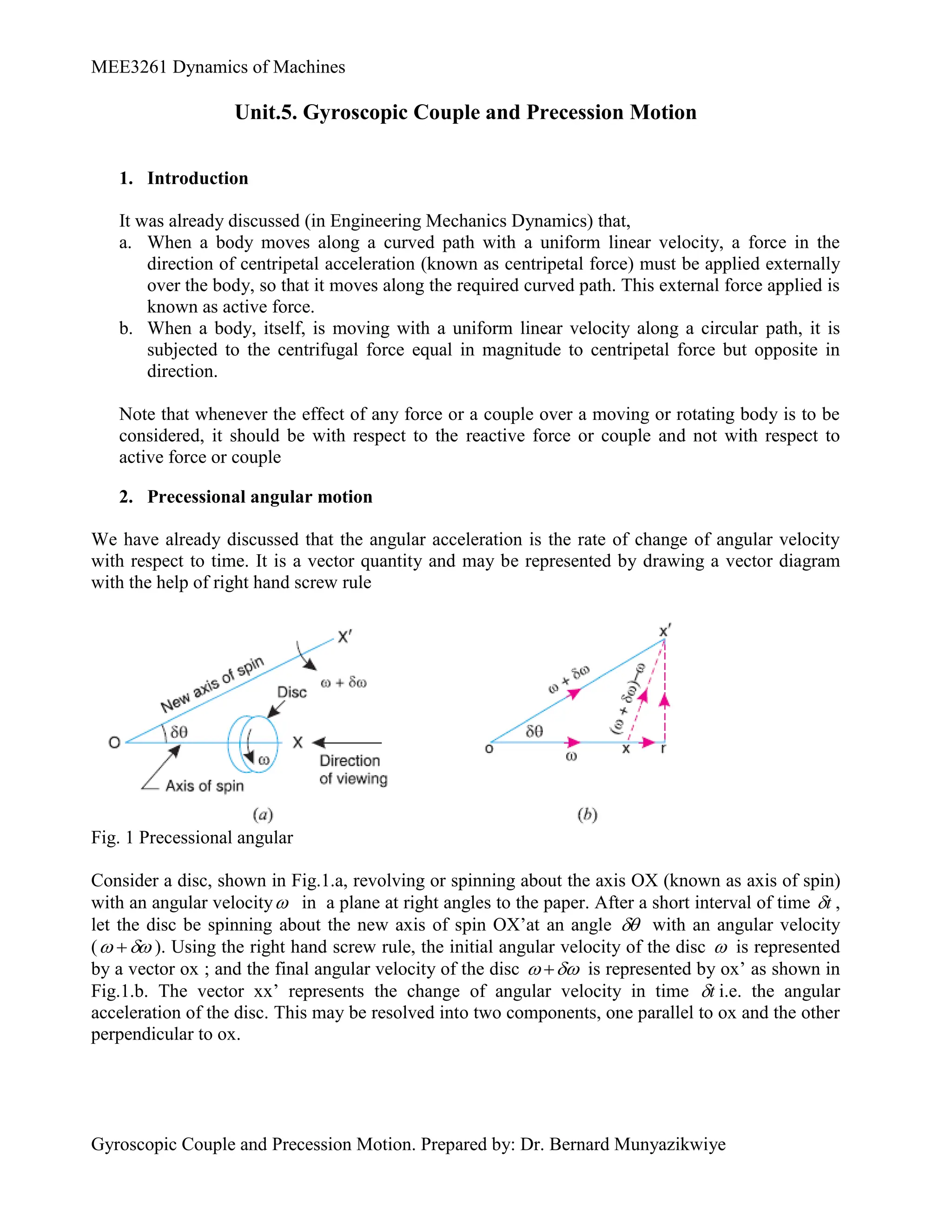
2. Precessional angular motion
We have already discussed that the angular acceleration is the rate of change of angular velocity
with respect to time. It is a vector quantity and may be represented by drawing a vector diagram
with the help of right hand screw rule
Fig. 1 Precessional angular
Consider a disc, shown in Fig.1.a, revolving or spinning about the axis OX (known as axis of spin)
with an angular velocity in a plane at right angles to the paper. After a short interval of time t
,
let the disc be spinning about the new axis of spin OX’at an angle with an angular velocity
(
). Using the right hand screw rule, the initial angular velocity of the disc is represented
by a vector ox ; and the final angular velocity of the disc
is represented by ox’ as shown in
Fig.1.b. The vector xx’ represents the change of angular velocity in time t
i.e. the angular
acceleration of the disc. This may be resolved into two components, one parallel to ox and the other
perpendicular to ox.
2.
MEE3261 Dynamics ofMachines
Gyroscopic Couple and Precession Motion. Prepared by: Dr. Bernard Munyazikwiye
Component of angular acceleration in the direction of ox,
t
t
t
ox
ox
t
ox
or
t
xr
t
cos
cos
cos
)
(
cos
'
Since is very small, therefore substituting 1
cos
, we have
t
t
t
In limit, when 0
t
,
dt
d
t
t
)
lim(
Component of angular acceleration in the direction perpendicular to ox,
t
t
t
ox
t
rx
c
sin
sin
sin
)
(
sin
'
'
Since is very small, therefore substituting
sin , we have
t
t
c
.
.
.
.........(Neglecting δω, δθ,beingverysmall)
In limit, when 0
t
,
p
c
dt
d
t
Lt
.
.
,
dθ
.........Substituting =ω
dt
p
The total angular acceleration of the disc
t c
= vector xx' = vector sum of α and α
. p
d d d
dt dt dt
Where
dt
d is the angular velocity of the axis of spin about a certain axis, which is perpendicular
to the plane in which the axis of spin is going to rotate. This angular velocity of the axis of spin is
known as angular velocity of precession and is denoted by p
. The axis, about which the axis of
spin is to turn, is known as axis of precession. The angular motion of the axis of spin about the axis
of precession is known as precessional angular motion.
Notes:
1. The axis of precession is perpendicular to the plane in which the axis of spin is going to rotate.
2. If the angular velocity of the disc remains constant at all positions of the axis of spin, then
dt
d is zero: and thus c
is zero.
3. If the angular velocity of the disc changes the direction, but remains constant in magnitude, then
angular acceleration of the disc is given by
3.
MEE3261 Dynamics ofMachines
Gyroscopic Couple and Precession Motion. Prepared by: Dr. Bernard Munyazikwiye
p
c
dt
d
.
.
The angular acceleration c
is known as gyroscopic acceleration.
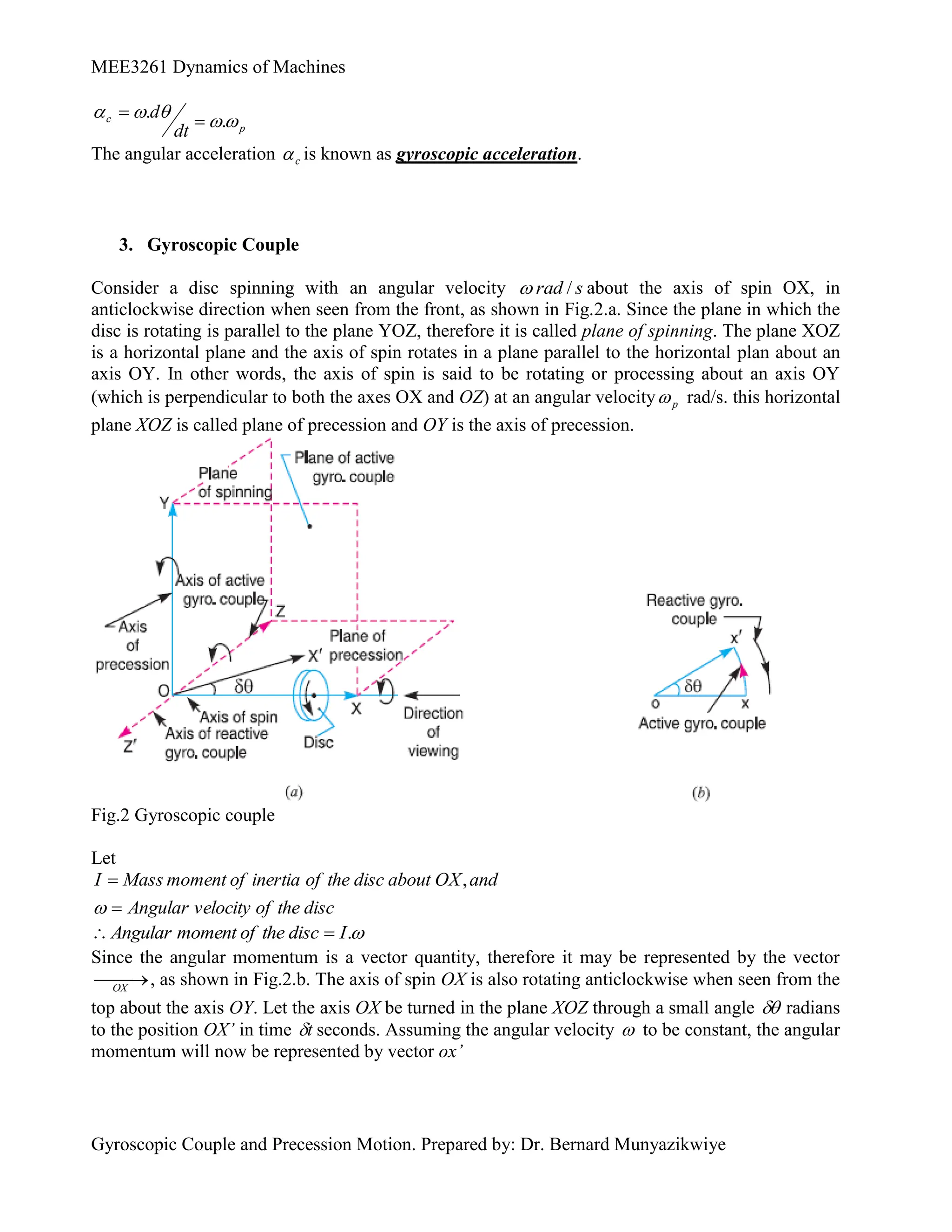
3. Gyroscopic Couple
Consider a disc spinning with an angular velocity s
rad /
about the axis of spin OX, in
anticlockwise direction when seen from the front, as shown in Fig.2.a. Since the plane in which the
disc is rotating is parallel to the plane YOZ, therefore it is called plane of spinning. The plane XOZ
is a horizontal plane and the axis of spin rotates in a plane parallel to the horizontal plan about an
axis OY. In other words, the axis of spin is said to be rotating or processing about an axis OY
(which is perpendicular to both the axes OX and OZ) at an angular velocity p
rad/s. this horizontal
plane XOZ is called plane of precession and OY is the axis of precession.
Fig.2 Gyroscopic couple
Let
disc
the
of
velocity
Angular
and
OX
about
disc
the
of
inertia
of
moment
Mass
I ,
.
I
disc
the
of
moment
Angular
Since the angular momentum is a vector quantity, therefore it may be represented by the vector
OX
, as shown in Fig.2.b. The axis of spin OX is also rotating anticlockwise when seen from the
top about the axis OY. Let the axis OX be turned in the plane XOZ through a small angle radians
to the position OX’ in time t
seconds. Assuming the angular velocity to be constant, the angular
momentum will now be represented by vector ox’
4.
MEE3261 Dynamics ofMachines
Gyroscopic Couple and Precession Motion. Prepared by: Dr. Bernard Munyazikwiye
I
ox
xx
ox
ox
momentum
angular
in
Change
.
'
' )
'
........( xx
of
direction
the
in
And the rate of change of angular momentum
dt
I
Since the rate of change of angular momentum will result by the application of a couple to the disc,
therefore the couple applied to the disc causing precession,
0
.
.
t
I
dt
d
I
t
I
Lt
C p
)
.......( p
dt
d
Where
OY.
precession
of
axis
about the
spin
of
axis
he
t
of
rotation
of
speed
or the
spin
of
axis
the
of
precession
of
locity
Angular ve
ωP
In SI units, the unit of C is N-m when I is in kg-m2
. It may be noted that
1. The couple P
I
. , in the direction of the vector '
xx (representing the change in angular
momentum) is the active gyroscopic couple, which has to be applied over the disc when the axis
of spin is made to rotate with angular velocity P
about the axis of precession. The vector
'
xx lies in the plane XOZ or the horizontal plane. In case of a very small displacement , the
vector '
xx will be perpendicular to the vertical plane XOY. Therefore the couple causing this
change in the angular momentum will lie in the plane XOY. The vector '
xx , as shown in
Fig.2(b), represents an anticlockwise couple in the plane XOY. Therefore, the plane XOY is
called the plane of active gyroscopic couple and the axis OZ perpendicular to the plane XOY,
about which the couple acts, is called the axis of active gyroscopic couple.
2. When the axis of spin itself moves with angular velocity P
the disc is subjected to reactive
couple whose magnitude is same (i.e P
I
. ) but opposite in the direction to that of active
couple. This reactive couple to which the disc is subjected when the axis of spin rotates about
the axis of precession is known as reactive gyroscopic couple. The axis of the reactive
gyroscopic couple is represented by OZ’ in Fig.2(a)
3. The gyroscopic couple is usually applied through the bearings which support the shaft. The
bearings will resist equal and opposite couple.
4. The gyroscopic principle is used in an instrument known as gyroscope. The gyroscopes are
installed in ships in order to minimize the rolling and pitching effects of waves. They are also
used in aeroplanes, monorails cars, gyrocompasses etc.
Example
A uniform disc of diameter 300mm and of mass 5kg is mounted on one end of an arm of
length 600mm. The other end of the arm is free to rotate in a universal bearing. If the disc
rotates about the arm with a speed of 300 rpm clockwise, looking from the front, with what
speed will it precess about the vertical axis?
5.
MEE3261 Dynamics ofMachines
Gyroscopic Couple and Precession Motion. Prepared by: Dr. Bernard Munyazikwiye
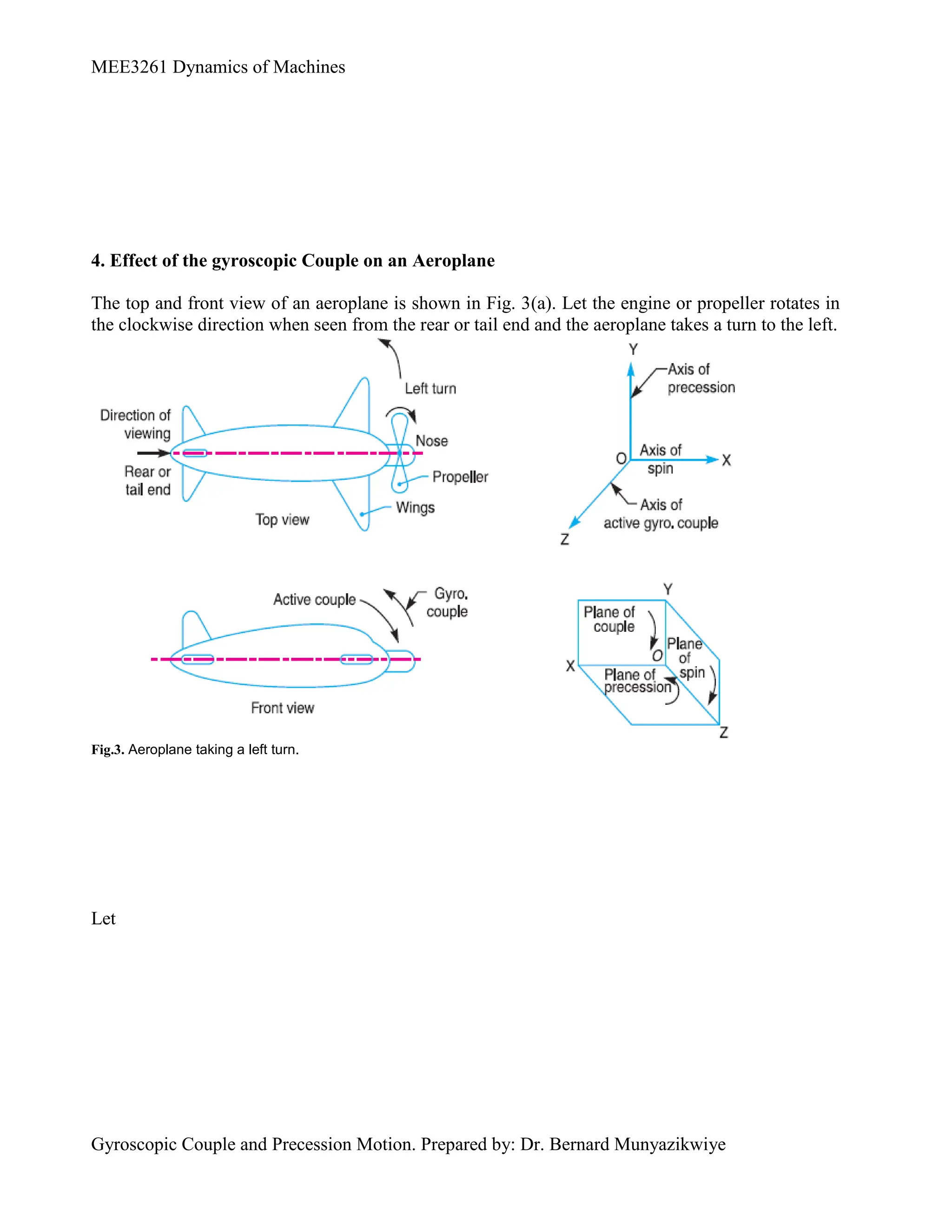
4. Effect of the gyroscopic Couple on an Aeroplane
The top and front view of an aeroplane is shown in Fig. 3(a). Let the engine or propeller rotates in
the clockwise direction when seen from the rear or tail end and the aeroplane takes a turn to the left.
Fig.3. Aeroplane taking a left turn.
Let
6.
MEE3261 Dynamics ofMachines
Gyroscopic Couple and Precession Motion. Prepared by: Dr. Bernard Munyazikwiye
rad/s
R
v
precession
of
locity
Angular ve
ω
and
metres,
in
curvature
of
Radius
R
m/s
in
aeroplane
the
of
ocity
Linear vel
v
,
m.k
m
kg
in
propeller
the
and
engine
the
of
inertia
of
moment
Mass
I
metres,
in
gyration
of
radius
Its
k
kg,
in
propeller
the
and
engine
the
of
Mass
m
rad/s,
in
engine
the
of
locity
Angular ve
ω
P
2
2
Gyroscopic couple acting on the aeroplane,
. . P
C I
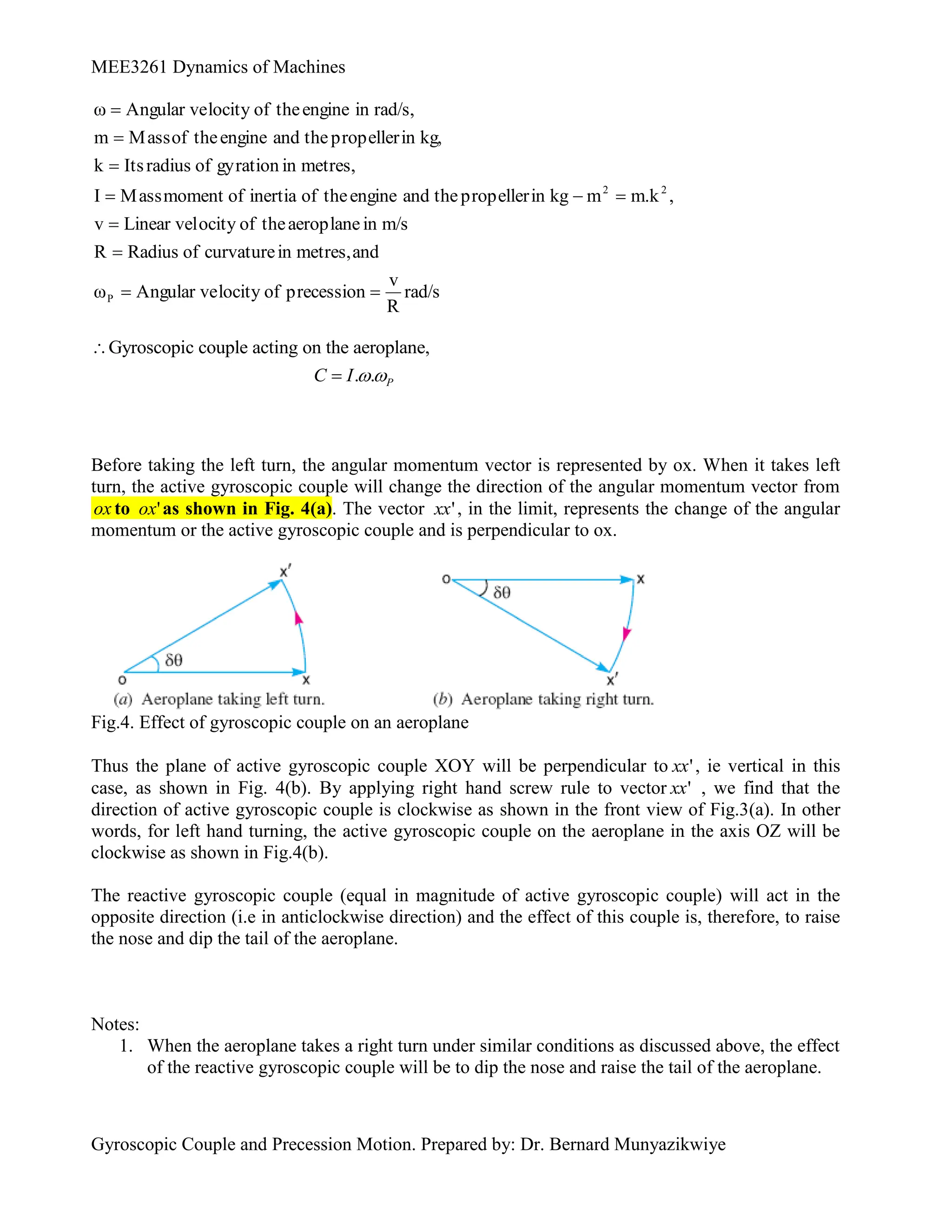
Before taking the left turn, the angular momentum vector is represented by ox. When it takes left
turn, the active gyroscopic couple will change the direction of the angular momentum vector from
ox to '
ox as shown in Fig. 4(a). The vector '
xx , in the limit, represents the change of the angular
momentum or the active gyroscopic couple and is perpendicular to ox.
Fig.4. Effect of gyroscopic couple on an aeroplane
Thus the plane of active gyroscopic couple XOY will be perpendicular to '
xx , ie vertical in this
case, as shown in Fig. 4(b). By applying right hand screw rule to vector '
xx , we find that the
direction of active gyroscopic couple is clockwise as shown in the front view of Fig.3(a). In other
words, for left hand turning, the active gyroscopic couple on the aeroplane in the axis OZ will be
clockwise as shown in Fig.4(b).
The reactive gyroscopic couple (equal in magnitude of active gyroscopic couple) will act in the
opposite direction (i.e in anticlockwise direction) and the effect of this couple is, therefore, to raise
the nose and dip the tail of the aeroplane.
Notes:
1. When the aeroplane takes a right turn under similar conditions as discussed above, the effect
of the reactive gyroscopic couple will be to dip the nose and raise the tail of the aeroplane.
7.
MEE3261 Dynamics ofMachines
Gyroscopic Couple and Precession Motion. Prepared by: Dr. Bernard Munyazikwiye
2. When the engine or propeller rotates in anticlockwise direction when viewed from the rear
or tail end and the aeroplane takes a left turn, then the effect of reactive gyroscopic couple
will be to dip the nose and raise the tail of the aeroplane.
3. When the aeroplane takes a right turn under similar conditions as mentioned in note 2
above, the effect of reactive gyroscopic couple will be to raise the nose and dip tail of the
aeroplane.
4. When the engine or propeller rotates in clockwise direction when viewed from the front and
the aeroplane takes a left turn, then the effect of reactive gyroscopic couple will be to raise
the tail and dip the nose of the aeroplane.
5. When the aeroplane takes a right turn under similar conditions as mentioned in note 4
above, the effect of reactive gyroscopic couple will be to raise the nose and dip the tail of
the aeroplane.
Example
An aeroplane makes a complete half cycle of 50 meters radius, towards left, when flying at
200km per hr. the rotary engine and the propeller of the plane has a mass of 400kg and a
radius of gyration of 0.3 m. the engine rotates at 2400rpm clockwise when viewed from the
rear. Find the gyroscopic couple on the aircraft and state its effect on it.
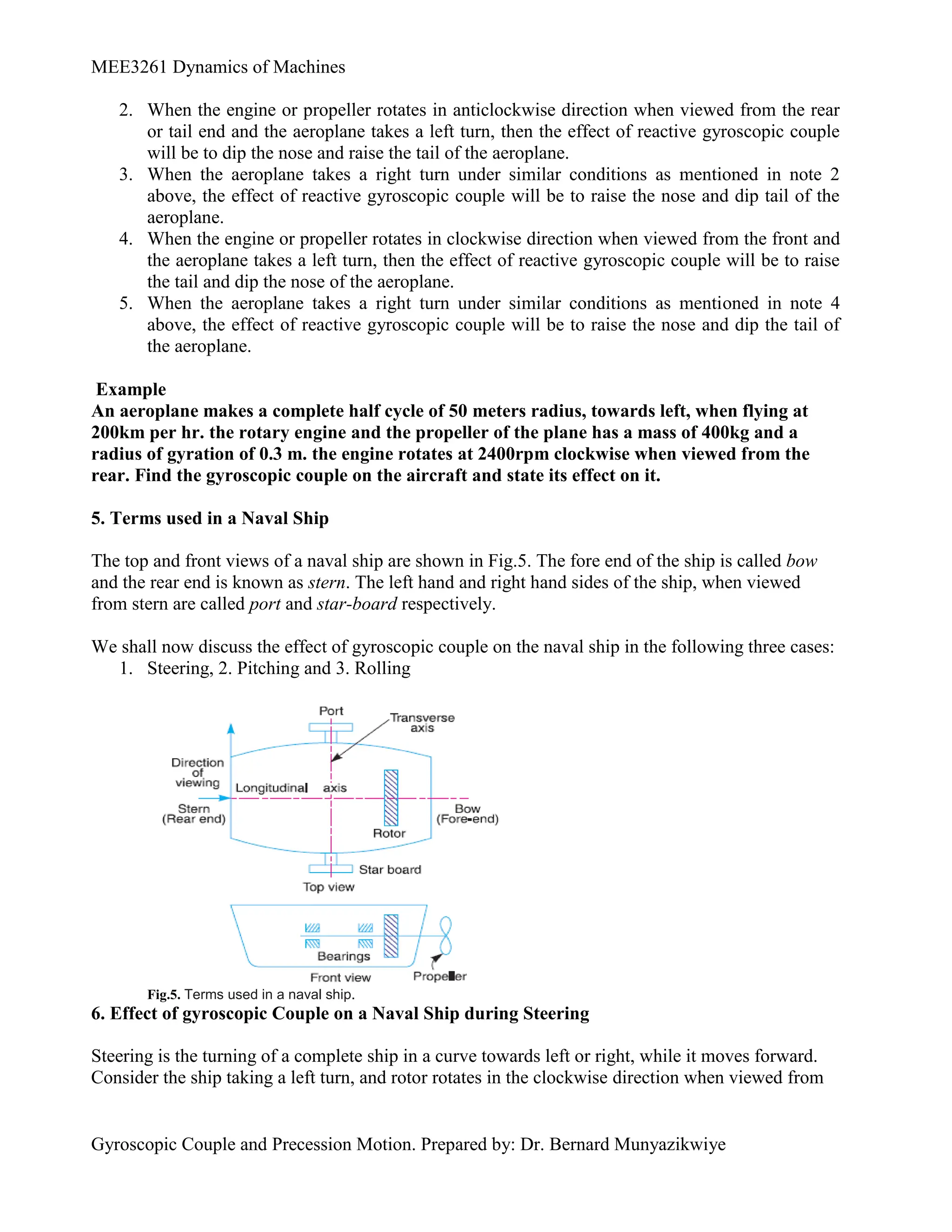
5. Terms used in a Naval Ship
The top and front views of a naval ship are shown in Fig.5. The fore end of the ship is called bow
and the rear end is known as stern. The left hand and right hand sides of the ship, when viewed
from stern are called port and star-board respectively.
We shall now discuss the effect of gyroscopic couple on the naval ship in the following three cases:
1. Steering, 2. Pitching and 3. Rolling
Fig.5. Terms used in a naval ship.
6. Effect of gyroscopic Couple on a Naval Ship during Steering
Steering is the turning of a complete ship in a curve towards left or right, while it moves forward.
Consider the ship taking a left turn, and rotor rotates in the clockwise direction when viewed from
8.
MEE3261 Dynamics ofMachines
Gyroscopic Couple and Precession Motion. Prepared by: Dr. Bernard Munyazikwiye
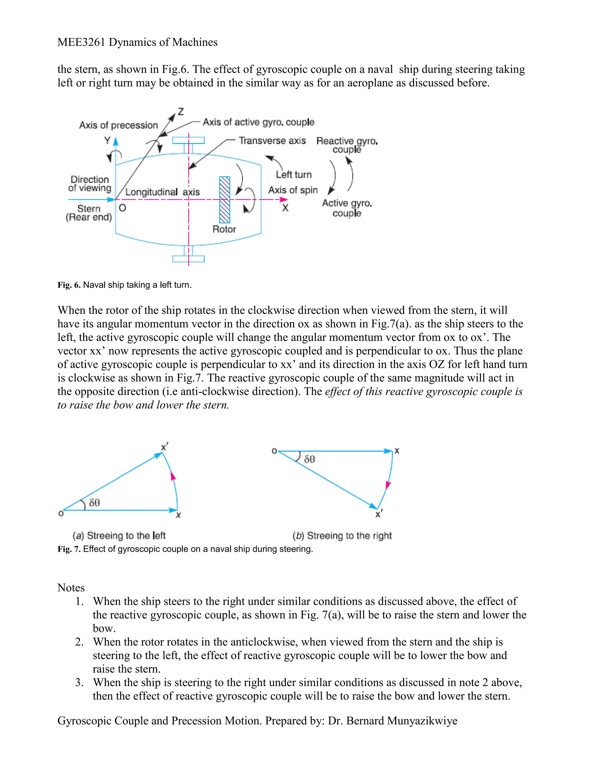
the stern, as shown in Fig.6. The effect of gyroscopic couple on a naval ship during steering taking
left or right turn may be obtained in the similar way as for an aeroplane as discussed before.
Fig. 6. Naval ship taking a left turn.
When the rotor of the ship rotates in the clockwise direction when viewed from the stern, it will
have its angular momentum vector in the direction ox as shown in Fig.7(a). as the ship steers to the
left, the active gyroscopic couple will change the angular momentum vector from ox to ox’. The
vector xx’ now represents the active gyroscopic coupled and is perpendicular to ox. Thus the plane
of active gyroscopic couple is perpendicular to xx’ and its direction in the axis OZ for left hand turn
is clockwise as shown in Fig.7. The reactive gyroscopic couple of the same magnitude will act in
the opposite direction (i.e anti-clockwise direction). The effect of this reactive gyroscopic couple is
to raise the bow and lower the stern.
Fig. 7. Effect of gyroscopic couple on a naval ship during steering.
Notes
1. When the ship steers to the right under similar conditions as discussed above, the effect of
the reactive gyroscopic couple, as shown in Fig. 7(a), will be to raise the stern and lower the
bow.
2. When the rotor rotates in the anticlockwise, when viewed from the stern and the ship is
steering to the left, the effect of reactive gyroscopic couple will be to lower the bow and
raise the stern.
3. When the ship is steering to the right under similar conditions as discussed in note 2 above,
then the effect of reactive gyroscopic couple will be to raise the bow and lower the stern.
9.
MEE3261 Dynamics ofMachines
Gyroscopic Couple and Precession Motion. Prepared by: Dr. Bernard Munyazikwiye
4. when the rotor rotates in the in the clockwise direction when viewed from the bow or fore
end and the ship is steering the left, then the effect of reactive gyroscopic couple will be to
raise the stern and lower the bow.
5. When the sheep is steering to the right under similar conditions as discussed in note 4
above, then the effect of reactive gyroscopic couple will be to raise the bow and lower the
stern.
6. The effect of the reactive gyroscopic couple on a boat propelled by the turbine taking left or
right turn is similar as discussed above.
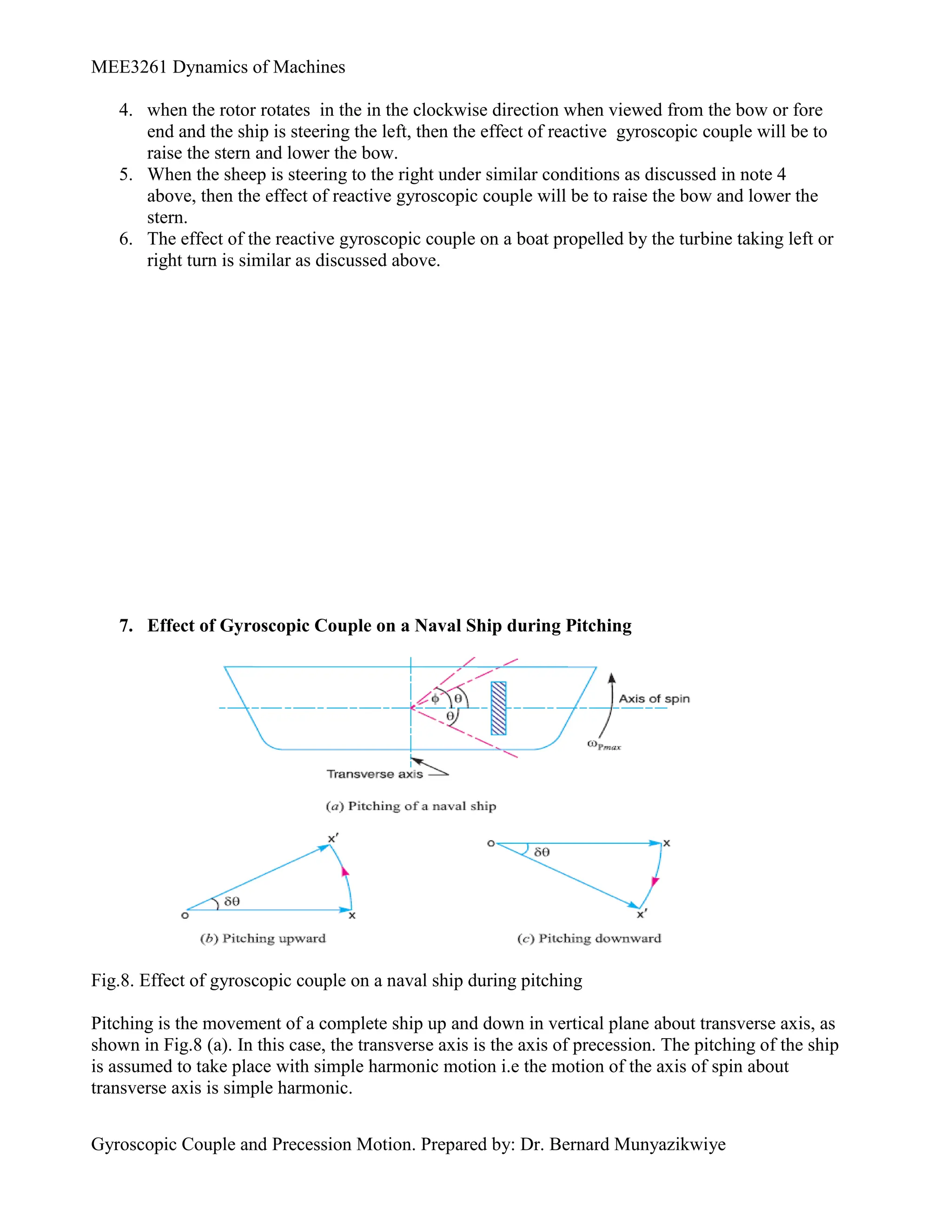
7. Effect of Gyroscopic Couple on a Naval Ship during Pitching
Fig.8. Effect of gyroscopic couple on a naval ship during pitching
Pitching is the movement of a complete ship up and down in vertical plane about transverse axis, as
shown in Fig.8 (a). In this case, the transverse axis is the axis of precession. The pitching of the ship
is assumed to take place with simple harmonic motion i.e the motion of the axis of spin about
transverse axis is simple harmonic.
10.
MEE3261 Dynamics ofMachines
Gyroscopic Couple and Precession Motion. Prepared by: Dr. Bernard Munyazikwiye
rad/s
t
2π
seconds
in
S.H.M
of
period
Time
2π
S.H.M
of
locity
angular ve
ω
and
radians,
in
position
mean
the
from
turned
angle
maximum
i.e
swing
of
amplitude
φ
where
.t
φsinω
θ
seconds,
t
after time
position
mean
from
spin
of
axis
the
of
nt
displaceme
Angular
p
1
1
Angular velocity of precession,
t
t
dt
d
dt
d
p .
cos
.
)
.
sin
( 1
1
1
The angular velocity of precession will be maximum, if 1
.
cos 1
t
p
p t
precession
of
velocity
angular
Maximum
/
2
.
,
1
max
)
1
.
cos
.....( 1
t
ng
Substituti
Let
s
rad
in
rotor
the
of
velocity
Angular
and
m
kg
in
rotor
the
of
inertia
of
Moment
I
/
,
2
max max
Maximum gyroscopic couple,
. . P
C I
When the pitching is upward the effect of the reactive gyroscopic couple, as shown in Fig. 8 (b),
will try to move the ship towards star-board. On the other hand, if the pitching is downward, the
effect of the reactive gyroscopic couple, as shown in Fig. 8 (c), is to turn the ship towards port side.
Note: 1. The effect of the gyroscopic couple is always given on specific position of axis of spin, i.e
whether it is pitching downwards or upwards.
2. The pitching of a ship produces forces on the bearing which act horizontally and
perpendicular to the motion of the ship.
3. The maximum of the gyroscopic couple tends to shear holding-down bolts.
4. The angular acceleration during pitching.
t
dt
d
1
1
2
2
sin
)
(
dθ
......(differentiating with respect to t
dt
)
The angular acceleration is maximum, if 1
sin 1
t
2
max 1
maximum angular acceleration during pitching,
8. Effect of Gyroscopic couple on a Naval ship during Rolling
We know that, for the effect of gyroscopic couple to occur, the axis of procession should always be
perpendicular to the axis of spin. If, however, the axis of procession becomes parallel to the axis of
spin, there will be no effect of the gyroscopic couple acting on the body of the ship.
11.
MEE3261 Dynamics ofMachines
Gyroscopic Couple and Precession Motion. Prepared by: Dr. Bernard Munyazikwiye
In case of rolling of a ship, the axis of procession (i.e. longitudinal axis) is always parallel to the
axis of spin for all positions. Hence, there is no effect of the gyroscopic couple acting on the body
of a ship.
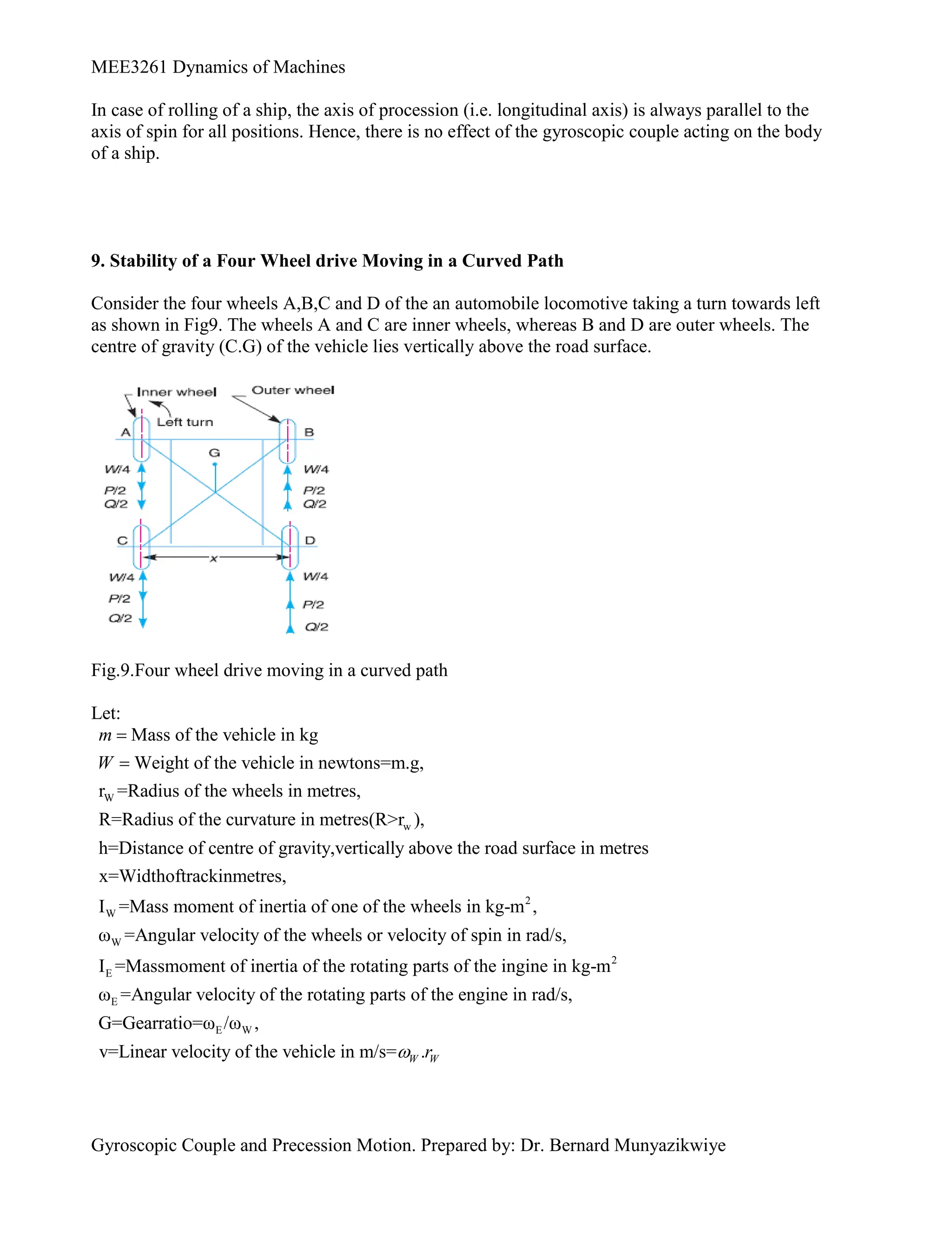
9. Stability of a Four Wheel drive Moving in a Curved Path
Consider the four wheels A,B,C and D of the an automobile locomotive taking a turn towards left
as shown in Fig9. The wheels A and C are inner wheels, whereas B and D are outer wheels. The
centre of gravity (C.G) of the vehicle lies vertically above the road surface.
Fig.9.Four wheel drive moving in a curved path
Let:
W
w
Mass of the vehicle in kg
Weight of the vehicle in newtons=m.g,
r =Radius of the wheels in metres,
R=Radius of the curvature in metres(R>r ),
h=Distance of centre of gravity,vertically above the road
m
W
2
W
W
E
surface in metres
x=Widthoftrackinmetres,
I =Mass moment of inertia of one of the wheels in kg-m ,
ω =Angular velocity of the wheels or velocity of spin in rad/s,
I =Massmoment of inertia of the rotating 2
E
E W
parts of the ingine in kg-m
ω =Angular velocity of the rotating parts of the engine in rad/s,
G=Gearratio=ω /ω ,
v=Linear velocity of the vehicle in m/s= .
W W
r
12.
MEE3261 Dynamics ofMachines
Gyroscopic Couple and Precession Motion. Prepared by: Dr. Bernard Munyazikwiye
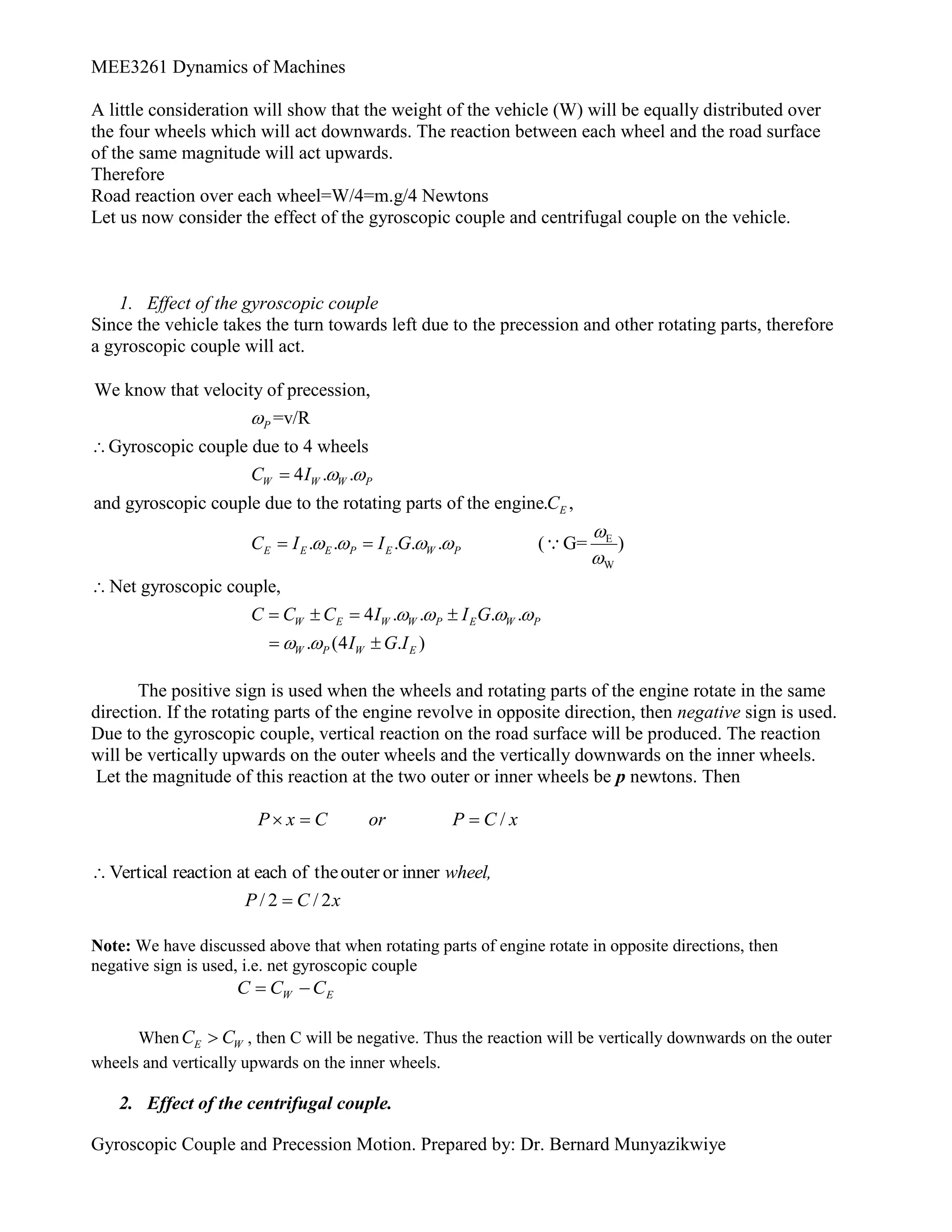
A little consideration will show that the weight of the vehicle (W) will be equally distributed over
the four wheels which will act downwards. The reaction between each wheel and the road surface
of the same magnitude will act upwards.
Therefore
Road reaction over each wheel=W/4=m.g/4 Newtons
Let us now consider the effect of the gyroscopic couple and centrifugal couple on the vehicle.
1. Effect of the gyroscopic couple
Since the vehicle takes the turn towards left due to the precession and other rotating parts, therefore
a gyroscopic couple will act.
E
W
We know that velocity of precession,
=v/R
Gyroscopic couple due to 4 wheels
4 . .
and gyroscopic couple due to the rotating parts of the engine. ,
. . . . . ( G= )
P
W W W P
E
E E E P E W P
C I
C
C I I G
Net gyroscopic couple,
4 . . . .
. (4 . )
W E W W P E W P
W P W E
C C C I I G
I G I
The positive sign is used when the wheels and rotating parts of the engine rotate in the same
direction. If the rotating parts of the engine revolve in opposite direction, then negative sign is used.
Due to the gyroscopic couple, vertical reaction on the road surface will be produced. The reaction
will be vertically upwards on the outer wheels and the vertically downwards on the inner wheels.
Let the magnitude of this reaction at the two outer or inner wheels be p newtons. Then
x
C
P
or
C
x
P /
x
C
P
wheel,
2
/
2
/
inner
or
outer
the
of
each
at
reaction
Vertical
Note: We have discussed above that when rotating parts of engine rotate in opposite directions, then
negative sign is used, i.e. net gyroscopic couple
E
W C
C
C
When E W
C C
, then C will be negative. Thus the reaction will be vertically downwards on the outer
wheels and vertically upwards on the inner wheels.
2. Effect of the centrifugal couple.
13.
MEE3261 Dynamics ofMachines
Gyroscopic Couple and Precession Motion. Prepared by: Dr. Bernard Munyazikwiye
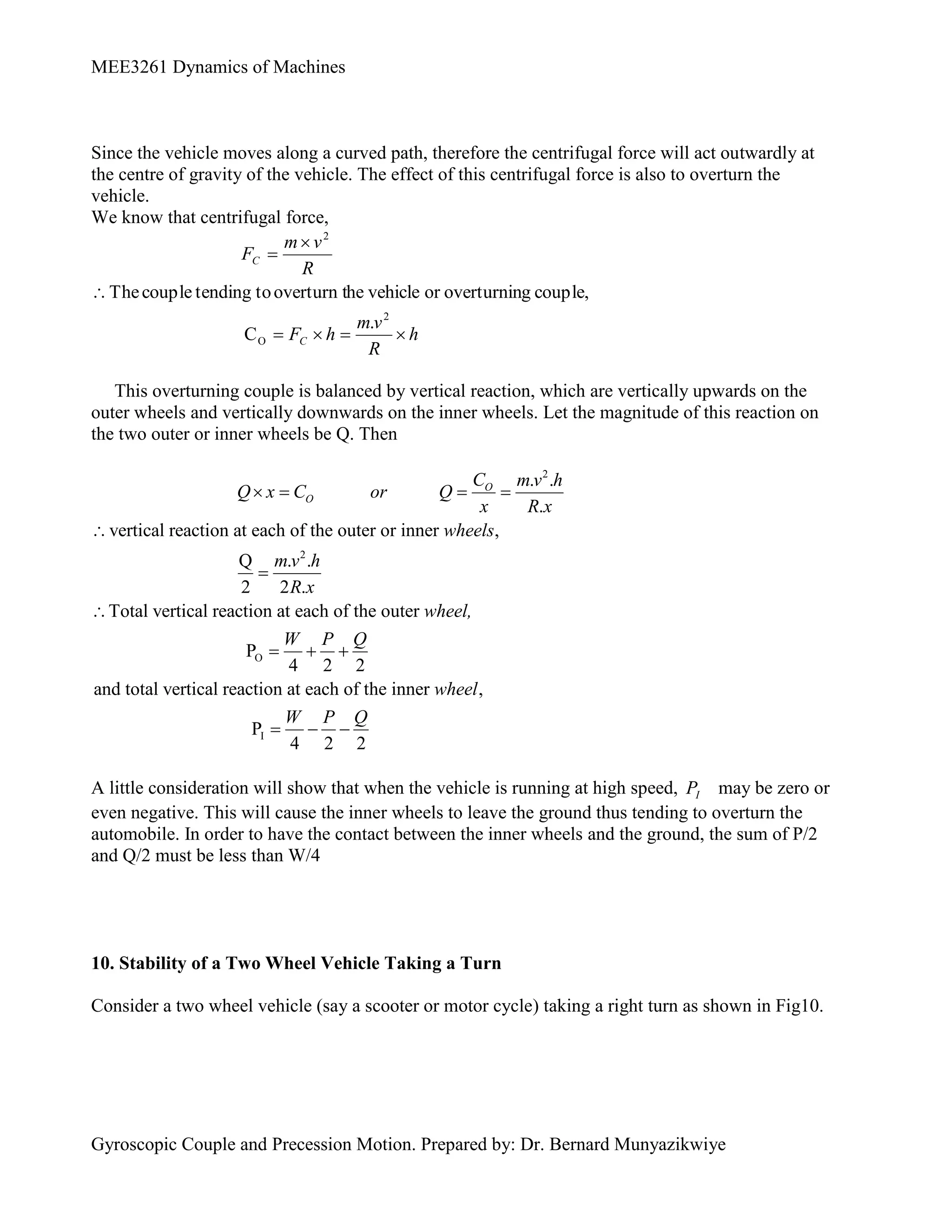
Since the vehicle moves along a curved path, therefore the centrifugal force will act outwardly at
the centre of gravity of the vehicle. The effect of this centrifugal force is also to overturn the
vehicle.
We know that centrifugal force,
h
R
v
m
h
F
R
v
m
F
C
C
2
O
2
.
C
couple,
g
overturnin
or
vehicle
he
overturn t
to
tending
couple
The
This overturning couple is balanced by vertical reaction, which are vertically upwards on the
outer wheels and vertically downwards on the inner wheels. Let the magnitude of this reaction on
the two outer or inner wheels be Q. Then
2
2
O
. .
.
vertical reaction at each of the outer or inner ,
Q . .
2 2 .
Total vertical reaction at each of the outer
P
4 2 2
and total vertical reaction at each of the i
O
O
C m v h
Q x C or Q
x R x
wheels
m v h
R x
wheel,
W P Q
I
nner ,
P
4 2 2
wheel
W P Q
A little consideration will show that when the vehicle is running at high speed, I
P may be zero or
even negative. This will cause the inner wheels to leave the ground thus tending to overturn the
automobile. In order to have the contact between the inner wheels and the ground, the sum of P/2
and Q/2 must be less than W/4
10. Stability of a Two Wheel Vehicle Taking a Turn
Consider a two wheel vehicle (say a scooter or motor cycle) taking a right turn as shown in Fig10.
14.
MEE3261 Dynamics ofMachines
Gyroscopic Couple and Precession Motion. Prepared by: Dr. Bernard Munyazikwiye
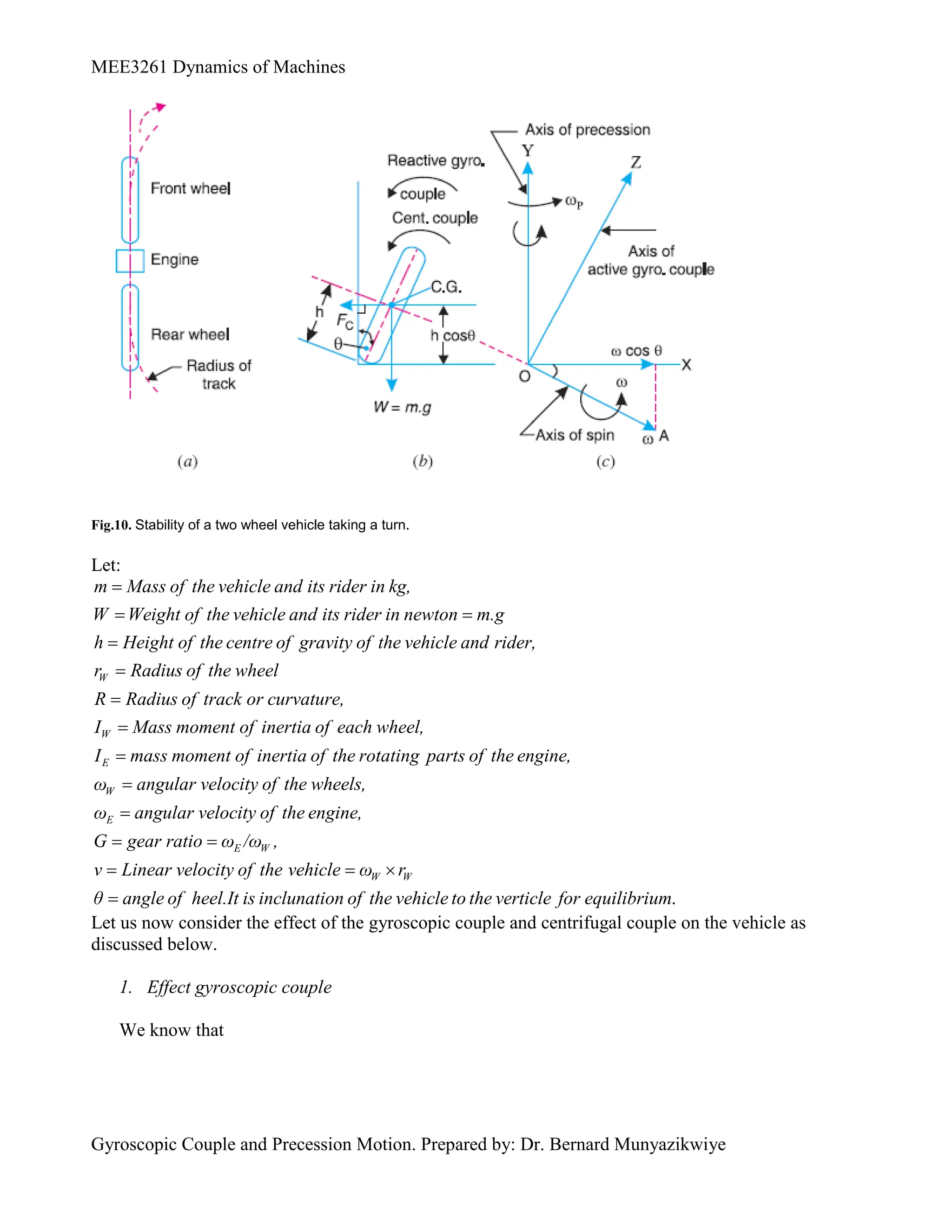
Fig.10. Stability of a two wheel vehicle taking a turn.
Let:
W
m Mass of the vehicle and its rider in kg,
W Weight of the vehicle and its rider in newton m.g
h Height of the centre of gravity of the vehicle and rider,
r Radius of the wheel
R Radius of track or curva
W
E
W
E
E W
ture,
I Mass moment of inertia of each wheel,
I mass moment of inertia of the rotating parts of the engine,
ω angular velocity of the wheels,
ω angular velocity of the engine,
G gear ratio ω /ω ,
v Line
.
W W
ar velocity of the vehicle ω r
θ angle of heel.It is inclunation of the vehicle to the verticle for equilibrium
Let us now consider the effect of the gyroscopic couple and centrifugal couple on the vehicle as
discussed below.
1. Effect gyroscopic couple
We know that
15.
MEE3261 Dynamics ofMachines
Gyroscopic Couple and Precession Motion. Prepared by: Dr. Bernard Munyazikwiye
and
r
v
G
G
r
v
or
r
v
W
W
E
W
W
W
W
.
/
)
.
2
(
2
2
)
(
E
W
W
W
E
W
W
E
E
W
W
I
G
I
r
v
r
v
G
I
r
v
I
I
I
I
Total
and velocity precession,
R
v/
A little consideration will show that the wheels move over the curved path, the vehicle is always
inclined at an angle θ with te vertical plane as shown in Fiig.10(b).
This angle is known as angle of heel. On other words, the axis of spin is inclined to the horizontal at
an angle , as shown in Fig.10 (c). Thus the angular momentum vector
I due to spin is
represented by OA inclined to OX at an angle . But the precession axis is vertical. Therefore the
spin vector is resolved along OX.
R
v
I
G
I
r
v
I
C
couple
Gyroscopic
E
w
w
p
cos
)
.
2
(
cos
1
cos
)
.
2
(
.
2
E
W
w
I
G
I
r
R
v
Notes:
1. When the engine is rotating in the same direction as that of wheels, the positive sign is used
in the above expression and if the engine rotates in opposite direction, then the negative sign
is used.
2. The gyroscopic couple will act over the vehicle outwards i.e in the anticlockwise direction
when seen from the front of the vehicle. The tendency of this couple is to overturn the
vehicle in outward direction.
2. Effect of centrifugal couple
We know that centrifugal force,
R
mv
Fc
2
This force acts horizontally through the centre of gravity (C.G) along the outward direction.
cos
)
(
cos
2
2 h
R
mv
h
F
C c
Since the centrifugal couple has a tendency to overturn the vehicle, therefore
Total overturning couple,
couple
l
Centrifuga
couple
gyroscopic
Co
16.
MEE3261 Dynamics ofMachines
Gyroscopic Couple and Precession Motion. Prepared by: Dr. Bernard Munyazikwiye
cos
cos
)
.
2
(
.
v 2
2
h
R
mv
I
G
I
r
R
E
w
w
cos
]
.
2
[
2
mh
r
I
G
I
R
v
w
E
w
We know that balancing couple
sin
.
.
. h
g
m
The balancing couple acts in clockwise direction when seen from the front of the vehicle. Therefore
for stability, the overturning couple must be the balancing couple, i.e
sin
.
.
.
cos
]
.
2
[
2
h
g
m
mh
r
I
G
I
R
v
w
E
w
From this expression, the value of the angle of heel may be determined, so that the vehicle does
not skid.
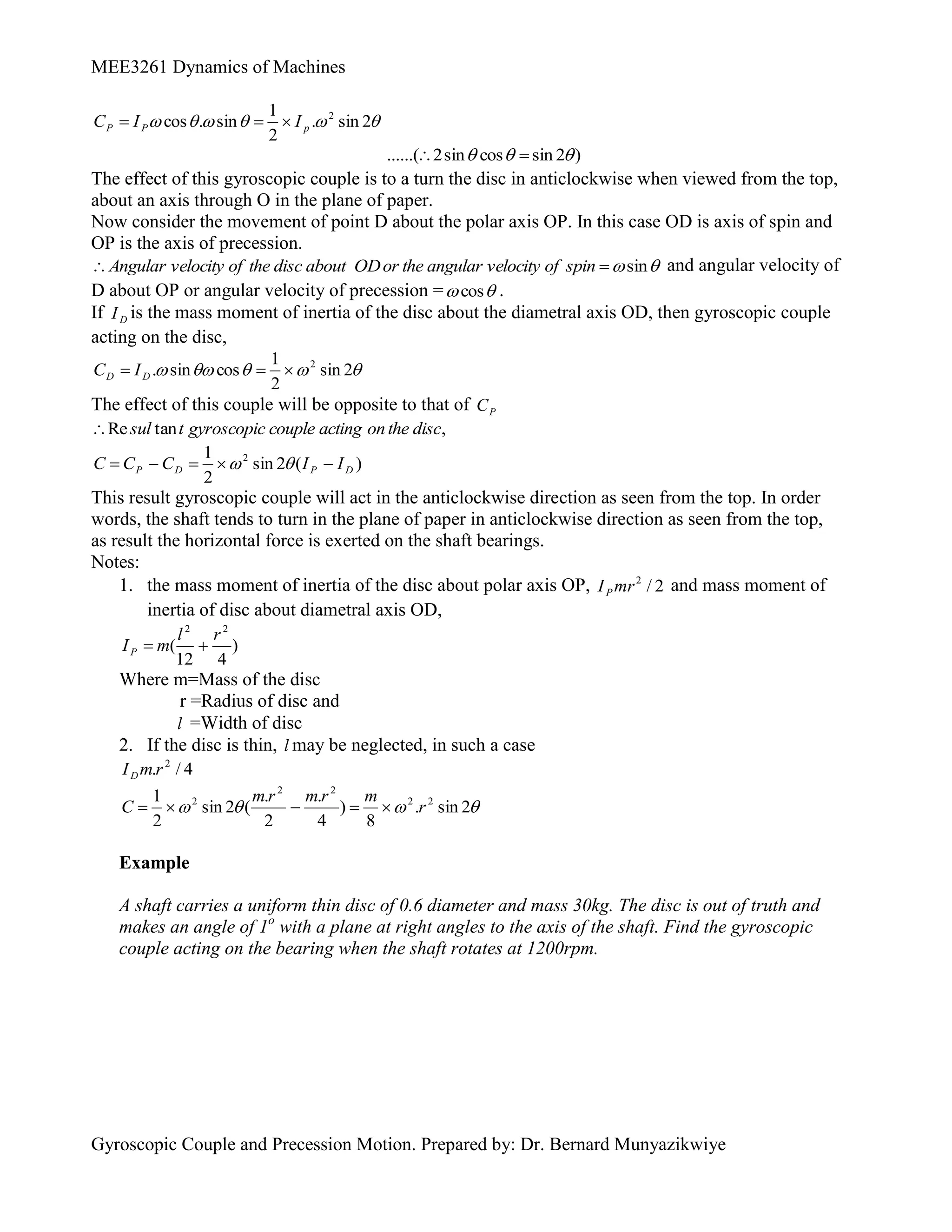
11. Effect f Gyroscopic Couple on a disc Fixed Rigidly at a Certain Angle to a Rotating
Consider a disc fixed rigidly to a rotating shaft such that the polar axis of the disc makes an angle
with the shaft axis, as shown in Fig.11.
Let the shaft rotates with an angle velocity ω rad/s in the clockwise direction when viewed from the
front. A little consideration will show that the disc will also rotate about OX with the same angular
velocity ω rad/s. Let OP be the polar axis and OD the diametral axis of the disc.
Fig. 11. Effect of gyroscopic couple on a disc fixed rigidly at a certain angle to a rotating shaft.
cos
spin
of
velocity
angular
the
or
OP
axis
polar
the
about
disc
the
of
velocity
Angular …..
(Component of ω in the direction of OP)
Since the shaft rotates, therefore the point P will move in a plane perpendicular to the plane of
paper. In other words, precession is produced about OD.
θ
ω
sion
of preces
r velocity
the angula
xis OD or
iametral a
bout the d
the disc a
locity of
Angular ve sin
if P
I is the mass moment of inertia of the disc about the polar axis OP, then gyroscopic couple
acting on the disc,
17.
MEE3261 Dynamics ofMachines
Gyroscopic Couple and Precession Motion. Prepared by: Dr. Bernard Munyazikwiye
2
sin
.
2
1
sin
.
cos 2
p
P
P I
I
C
)
2
sin
cos
sin
2
......(
The effect of this gyroscopic couple is to a turn the disc in anticlockwise when viewed from the top,
about an axis through O in the plane of paper.
Now consider the movement of point D about the polar axis OP. In this case OD is axis of spin and
OP is the axis of precession.
sin
spin
of
velocity
angular
the
or
OD
about
disc
the
of
velocity
Angular and angular velocity of
D about OP or angular velocity of precession =
cos .
If D
I is the mass moment of inertia of the disc about the diametral axis OD, then gyroscopic couple
acting on the disc,
2
sin
2
1
cos
sin
. 2
D
D I
C
The effect of this couple will be opposite to that of P
C
,
tan
Re disc
the
on
acting
couple
gyroscopic
t
sul
)
(
2
sin
2
1 2
D
P
D
P I
I
C
C
C
This result gyroscopic couple will act in the anticlockwise direction as seen from the top. In order
words, the shaft tends to turn in the plane of paper in anticlockwise direction as seen from the top,
as result the horizontal force is exerted on the shaft bearings.
Notes:
1. the mass moment of inertia of the disc about polar axis OP, 2
/
2
mr
IP and mass moment of
inertia of disc about diametral axis OD,
)
4
12
(
2
2
r
l
m
IP
Where m=Mass of the disc
r =Radius of disc and
l =Width of disc
2. If the disc is thin, l may be neglected, in such a case
4
/
. 2
r
m
ID
2
sin
.
8
)
4
.
2
.
(
2
sin
2
1 2
2
2
2
2
r
m
r
m
r
m
C
Example
A shaft carries a uniform thin disc of 0.6 diameter and mass 30kg. The disc is out of truth and
makes an angle of 1o
with a plane at right angles to the axis of the shaft. Find the gyroscopic
couple acting on the bearing when the shaft rotates at 1200rpm.
![MEE3261 Dynamics of Machines
Gyroscopic Couple and Precession Motion. Prepared by: Dr. Bernard Munyazikwiye
cos
cos
)
.
2
(
.
v 2
2
h
R
mv
I
G
I
r
R
E
w
w
cos
]
.
2
[
2
mh
r
I
G
I
R
v
w
E
w
We know that balancing couple
sin
.
.
. h
g
m
The balancing couple acts in clockwise direction when seen from the front of the vehicle. Therefore
for stability, the overturning couple must be the balancing couple, i.e
sin
.
.
.
cos
]
.
2
[
2
h
g
m
mh
r
I
G
I
R
v
w
E
w
From this expression, the value of the angle of heel may be determined, so that the vehicle does
not skid.
11. Effect f Gyroscopic Couple on a disc Fixed Rigidly at a Certain Angle to a Rotating
Consider a disc fixed rigidly to a rotating shaft such that the polar axis of the disc makes an angle
with the shaft axis, as shown in Fig.11.
Let the shaft rotates with an angle velocity ω rad/s in the clockwise direction when viewed from the
front. A little consideration will show that the disc will also rotate about OX with the same angular
velocity ω rad/s. Let OP be the polar axis and OD the diametral axis of the disc.
Fig. 11. Effect of gyroscopic couple on a disc fixed rigidly at a certain angle to a rotating shaft.
cos
spin
of
velocity
angular
the
or
OP
axis
polar
the
about
disc
the
of
velocity
Angular …..
(Component of ω in the direction of OP)
Since the shaft rotates, therefore the point P will move in a plane perpendicular to the plane of
paper. In other words, precession is produced about OD.
θ
ω
sion
of preces
r velocity
the angula
xis OD or
iametral a
bout the d
the disc a
locity of
Angular ve sin
if P
I is the mass moment of inertia of the disc about the polar axis OP, then gyroscopic couple
acting on the disc,](https://image.slidesharecdn.com/unit-250213150134-d9cfea33/75/Unit-5-Gyroscopic-Couple-and-Precession-Motion-Lecture-notes-pdf-16-2048.jpg)