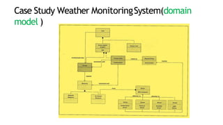
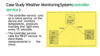
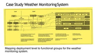
IOT Platforms DesignMethodology
It includes:
Purpose & Requirements
Specification
Process Specification
Domain Model Specification
Information Model Specification
Service Specification
IOT Platforms DesignMethodology
IoT Level Specifications
Functional view Specification
Operational View
Specification
Device & component
Integration
Application Development
Device & componentIntegration
The devices and components used in this example are Raspberry Pi mini computer, LDR
sensor and relay switch actuator.
Application Development
 The application has controls for the mode (auto on or auto
off) and the light (on or off).
 In the auto mode, the IoT system controls the light
appliance automatically based on the lighting
conditions in the room.
 When auto mode is enabled the light control in the
application is disabled and it reflects the current state of
the light.
 When the auto mode is disabled, the light control is enabled
and it is used for manually controlling the light.
Application Development
Case Study Weather MonitoringSystem
The purpose of the weather monitoring system is to
collect data on environmental conditions such as
temperature, pressure, humidity and light in an area
using multiple end nodes.
The end nodes send the data to the cloud where the data
is aggregated and analyzed.
Case Study Weather MonitoringSystem
Figure shows the process
specification for the
weather monitoring
system.
The process specification
shows that the sensors are
read after fixed intervals
and the sensor
measurements are stored.
Case Study Weather MonitoringSystem
In this domain model the physical entity is the
environment which is being monitored .
There is a virtual entity for the environment. Devices
include temperature sensor, pressure sensor, humidity
sensor, light sensor and single-board mini computer.
Resources are software components which can be
either on-device or network-resources.
Services include the controller service that monitors the
temperature , pressure deriving the services from the
process specification and information model for the
weather monitoring system, humidity and light and sends
the readings to the deriving the services from the process
specification and information model for the weather
monitoring system.
Case Study Weather MonitoringSystem(domain
model )
Case Study Weather MonitoringSystem(controller
service )
• The controller service runs
as a native service on the
device and monitors
temperature, pressure,
humidity and light once
every 15 seconds.
• The controller service
calls the REST service to
store these
measurements in the
cloud.
Case Study Weather MonitoringSystem
(deployment design for the system)
• The system consists of multiple nodes
placed in different locations for
monitoring temperature, humidity and
pressure in an area.
• The end nodes are equipped with
various sensors .
• The end nodes send the data to the
cloud and the data is stored in a cloud
database.
• The analysis of data is done in the
cloud to aggregate the data and make
predictions
Case Study Weather MonitoringSystem
Mapping deployment level to functional groups for the weather
monitoring system.
Case Study Weather MonitoringSystem
Mapping functional Groups to operational view specifications for the
weather monitoring system.
Case Study Weather MonitoringSystem(controller
service )
The schematic diagram
of the weather
monitoring system.
The devices and
components used in this
example are Raspberry
Pi mini computer,
temperature sensor,
humidity sensor,
pressure sensor and
LDR sensor.
Thankyou
Ref: IOT by Ashdeep Bahga &Vijay
Madisetti
5
1

Unit 4 -IOT5_Domain Model refrence .pptx

  • 1.
    IOT Platforms DesignMethodology Itincludes: Purpose & Requirements Specification Process Specification Domain Model Specification Information Model Specification Service Specification
  • 2.
    IOT Platforms DesignMethodology IoTLevel Specifications Functional view Specification Operational View Specification Device & component Integration Application Development
  • 3.
    Device & componentIntegration Thedevices and components used in this example are Raspberry Pi mini computer, LDR sensor and relay switch actuator.
  • 4.
    Application Development  Theapplication has controls for the mode (auto on or auto off) and the light (on or off).  In the auto mode, the IoT system controls the light appliance automatically based on the lighting conditions in the room.  When auto mode is enabled the light control in the application is disabled and it reflects the current state of the light.  When the auto mode is disabled, the light control is enabled and it is used for manually controlling the light.
  • 5.
  • 6.
    Case Study WeatherMonitoringSystem The purpose of the weather monitoring system is to collect data on environmental conditions such as temperature, pressure, humidity and light in an area using multiple end nodes. The end nodes send the data to the cloud where the data is aggregated and analyzed.
  • 7.
    Case Study WeatherMonitoringSystem Figure shows the process specification for the weather monitoring system. The process specification shows that the sensors are read after fixed intervals and the sensor measurements are stored.
  • 8.
    Case Study WeatherMonitoringSystem In this domain model the physical entity is the environment which is being monitored . There is a virtual entity for the environment. Devices include temperature sensor, pressure sensor, humidity sensor, light sensor and single-board mini computer. Resources are software components which can be either on-device or network-resources. Services include the controller service that monitors the temperature , pressure deriving the services from the process specification and information model for the weather monitoring system, humidity and light and sends the readings to the deriving the services from the process specification and information model for the weather monitoring system.
  • 9.
    Case Study WeatherMonitoringSystem(domain model )
  • 10.
    Case Study WeatherMonitoringSystem(controller service ) • The controller service runs as a native service on the device and monitors temperature, pressure, humidity and light once every 15 seconds. • The controller service calls the REST service to store these measurements in the cloud.
  • 11.
    Case Study WeatherMonitoringSystem (deployment design for the system) • The system consists of multiple nodes placed in different locations for monitoring temperature, humidity and pressure in an area. • The end nodes are equipped with various sensors . • The end nodes send the data to the cloud and the data is stored in a cloud database. • The analysis of data is done in the cloud to aggregate the data and make predictions
  • 12.
    Case Study WeatherMonitoringSystem Mapping deployment level to functional groups for the weather monitoring system.
  • 13.
    Case Study WeatherMonitoringSystem Mapping functional Groups to operational view specifications for the weather monitoring system.
  • 14.
    Case Study WeatherMonitoringSystem(controller service ) The schematic diagram of the weather monitoring system. The devices and components used in this example are Raspberry Pi mini computer, temperature sensor, humidity sensor, pressure sensor and LDR sensor.
  • 15.
    Thankyou Ref: IOT byAshdeep Bahga &Vijay Madisetti 5 1