Download to read offline
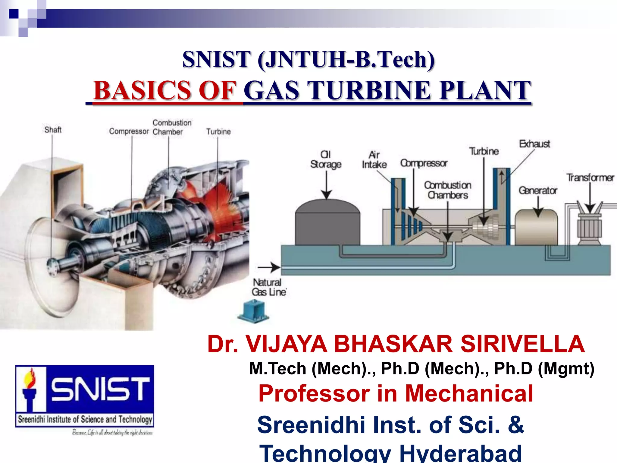

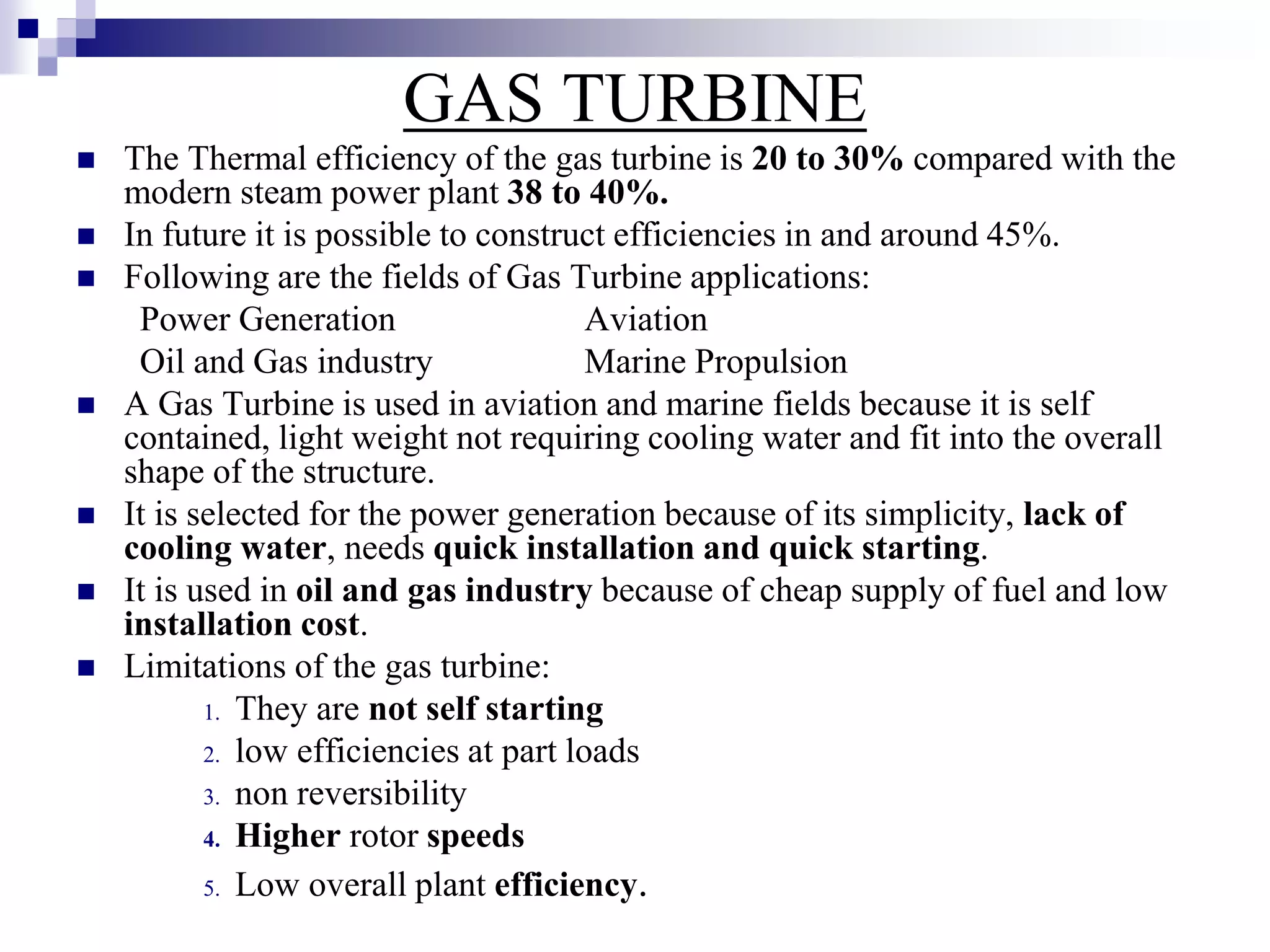


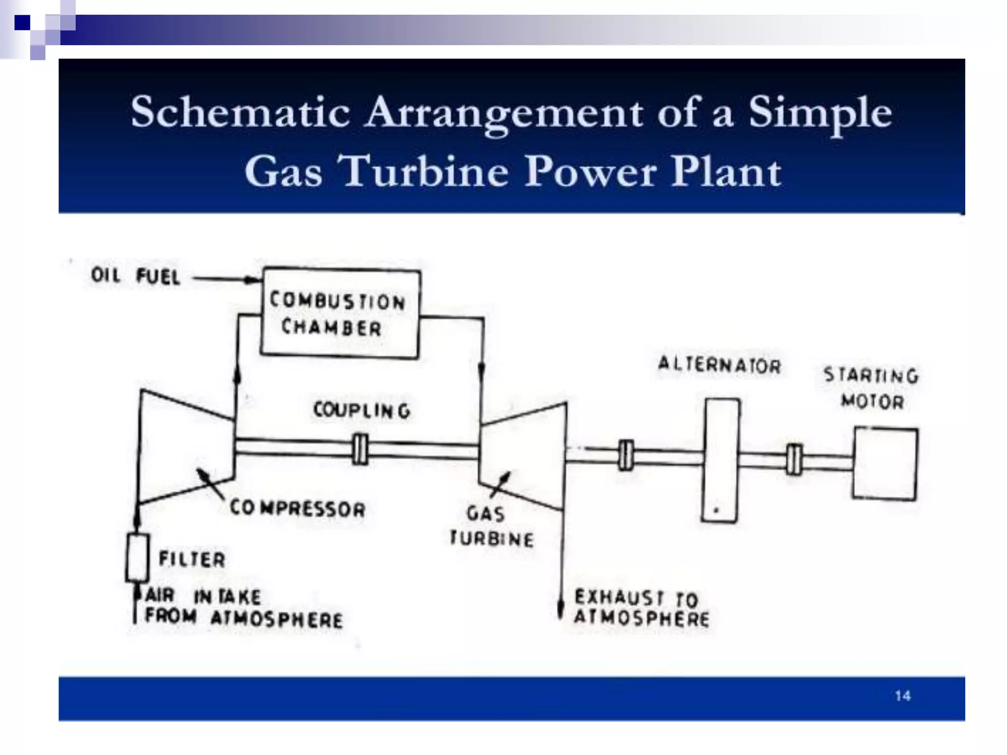


Gas turbine power plants can generate electricity quickly but have low efficiency. They work by compressing air, mixing it with fuel, and burning the mixture to drive a turbine. The turbine is connected to a generator to produce electricity. While gas turbines are simpler than steam plants, they have disadvantages like poor part-load efficiency and higher operating costs. Combined cycle plants that combine a gas and steam turbine can achieve higher overall efficiency.


