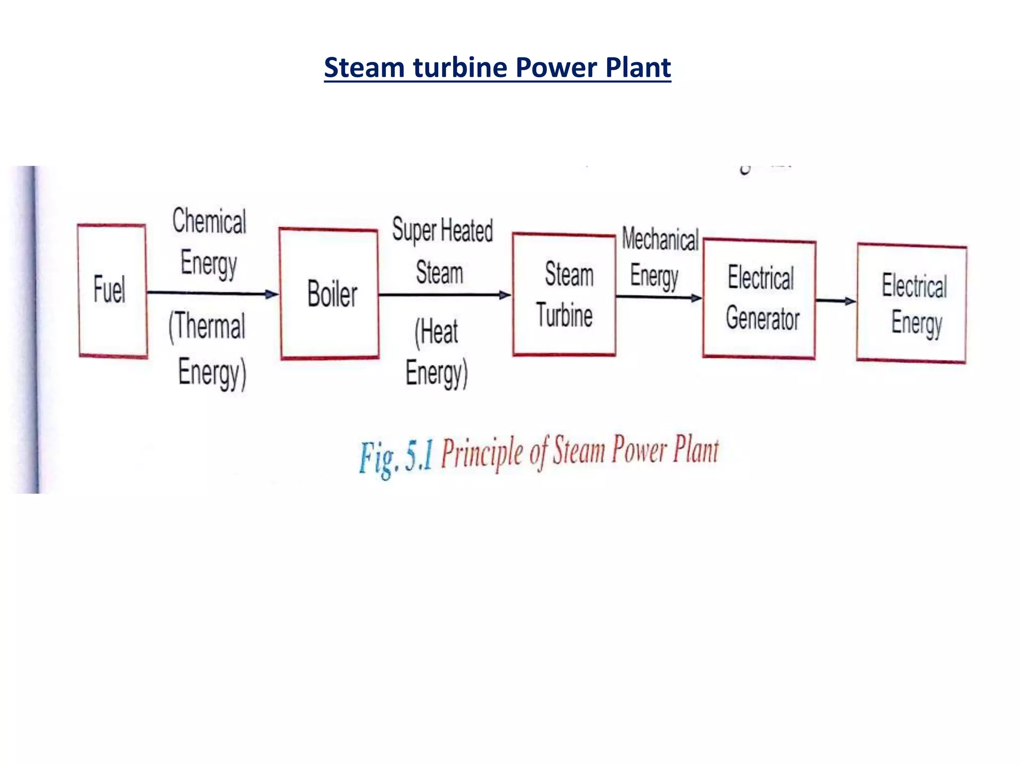
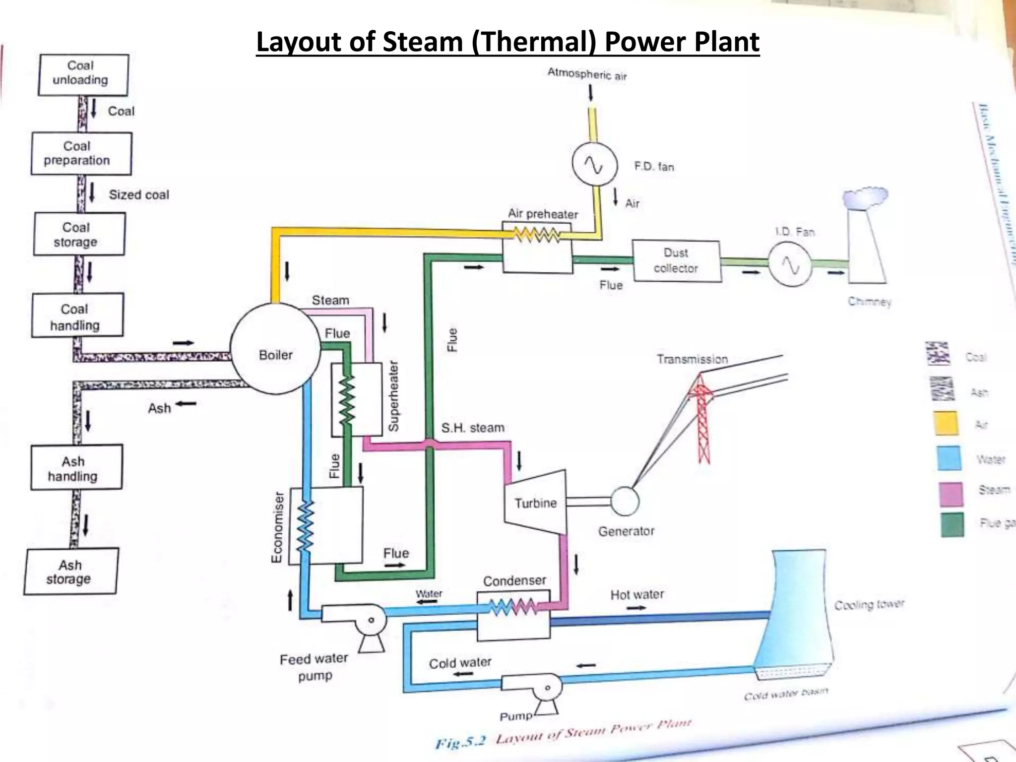
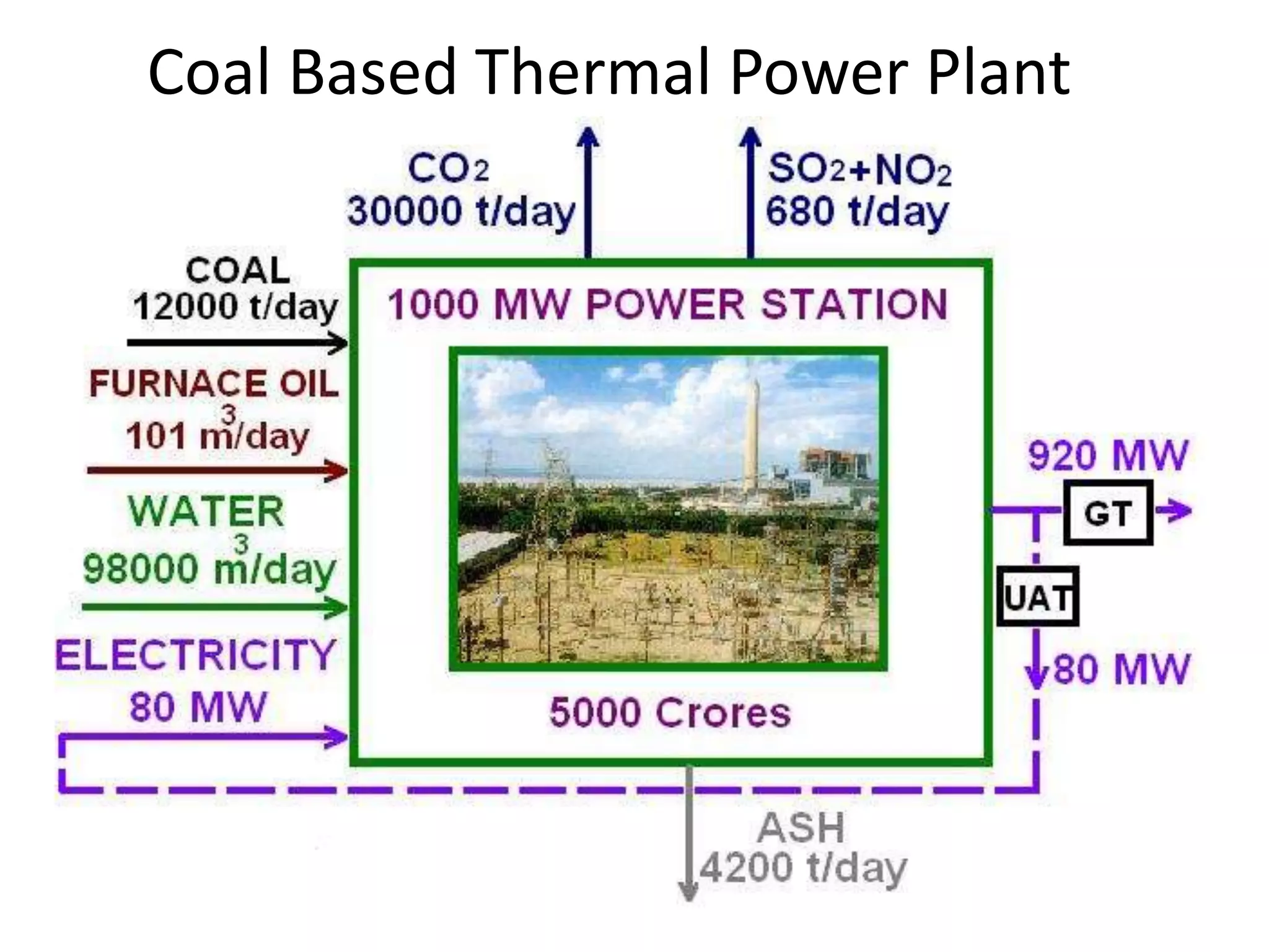
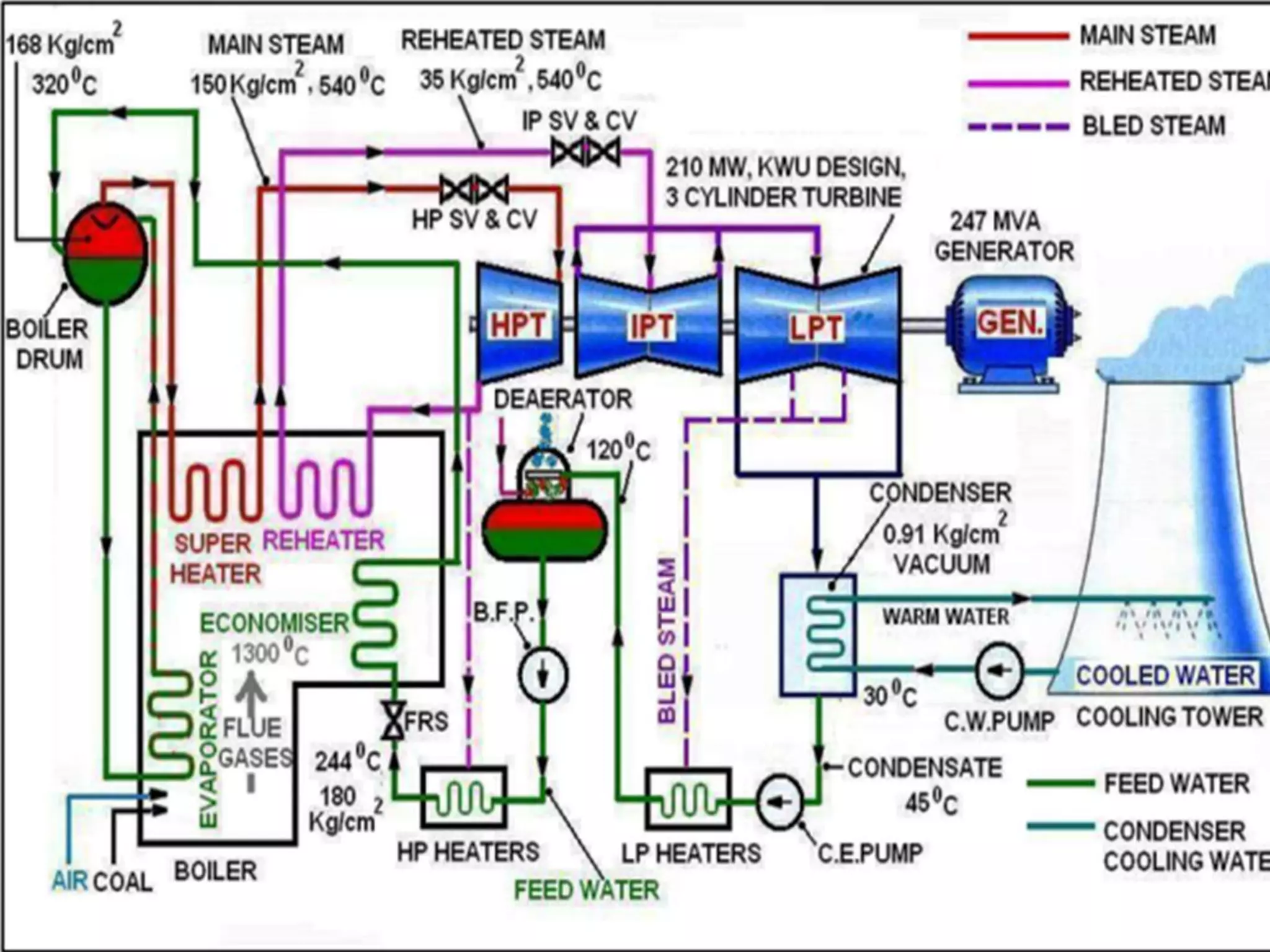
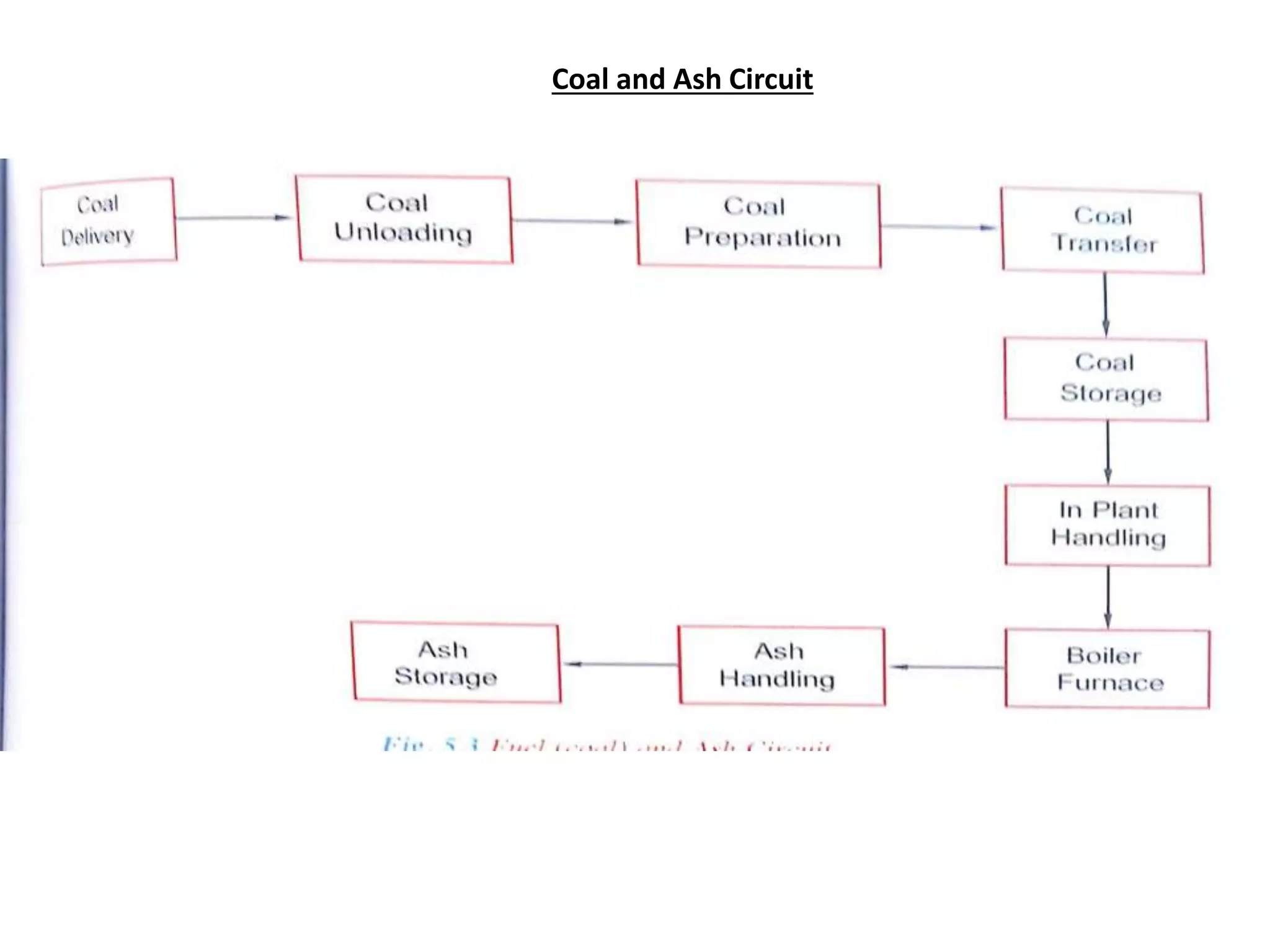
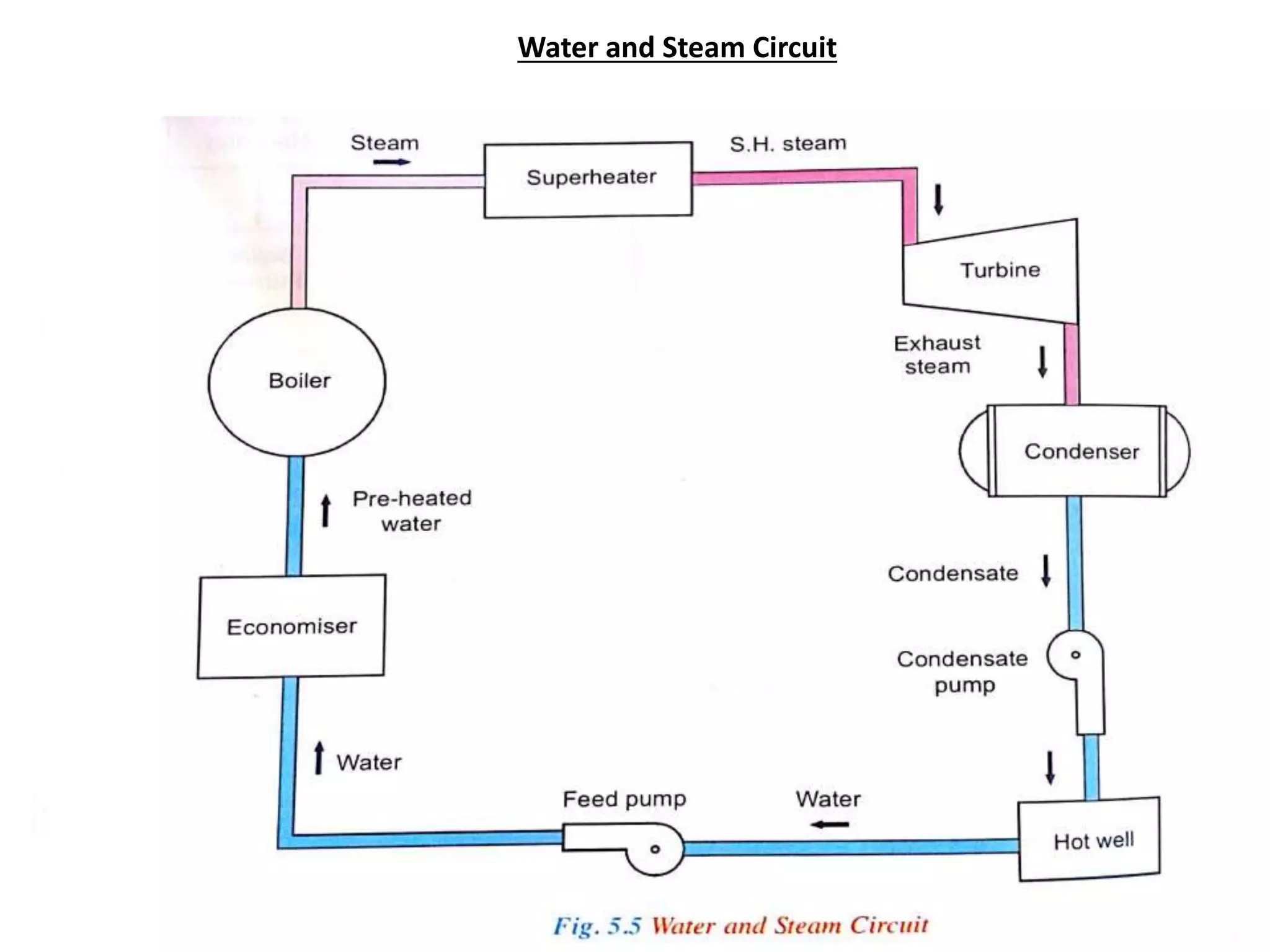
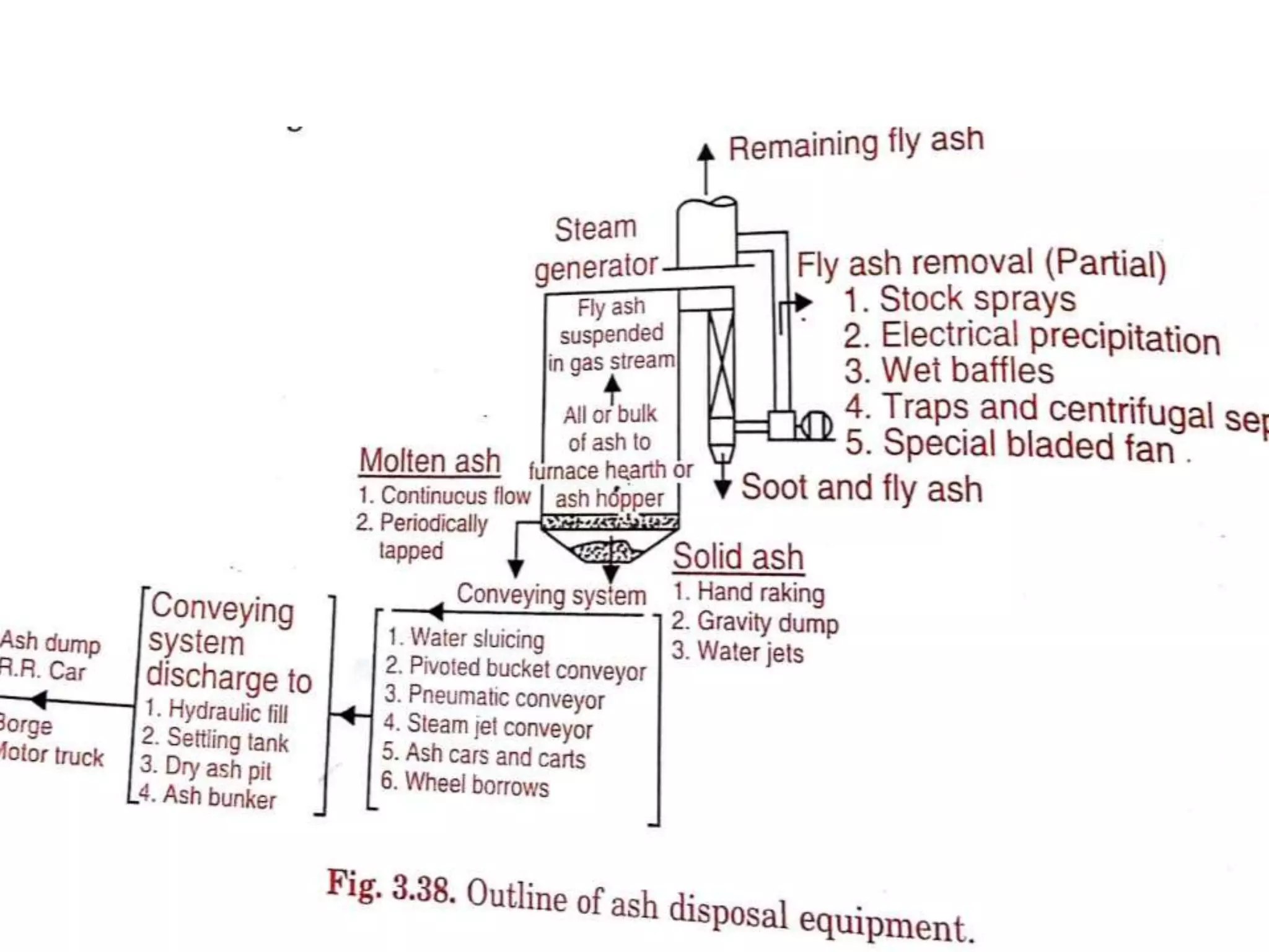
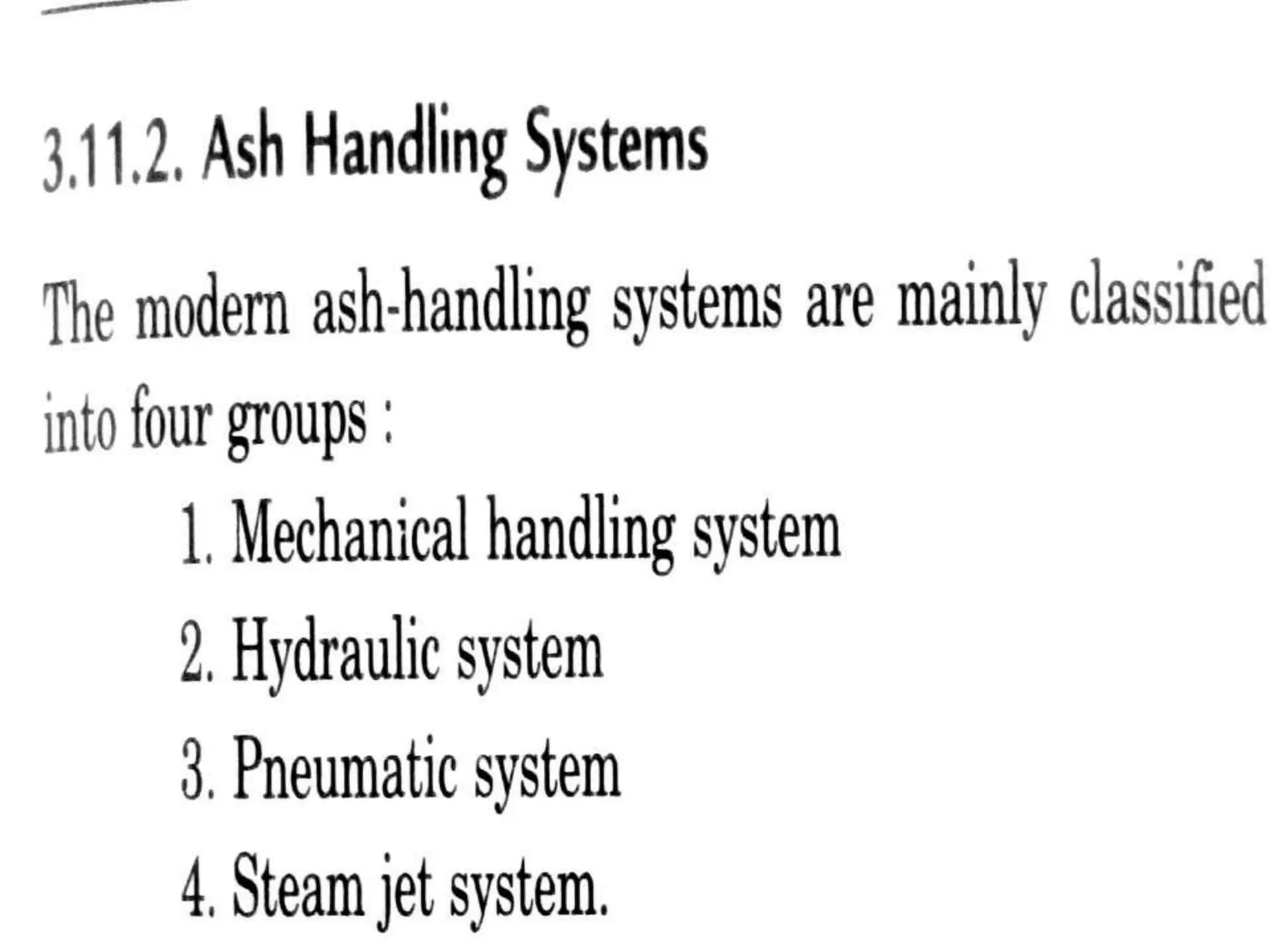
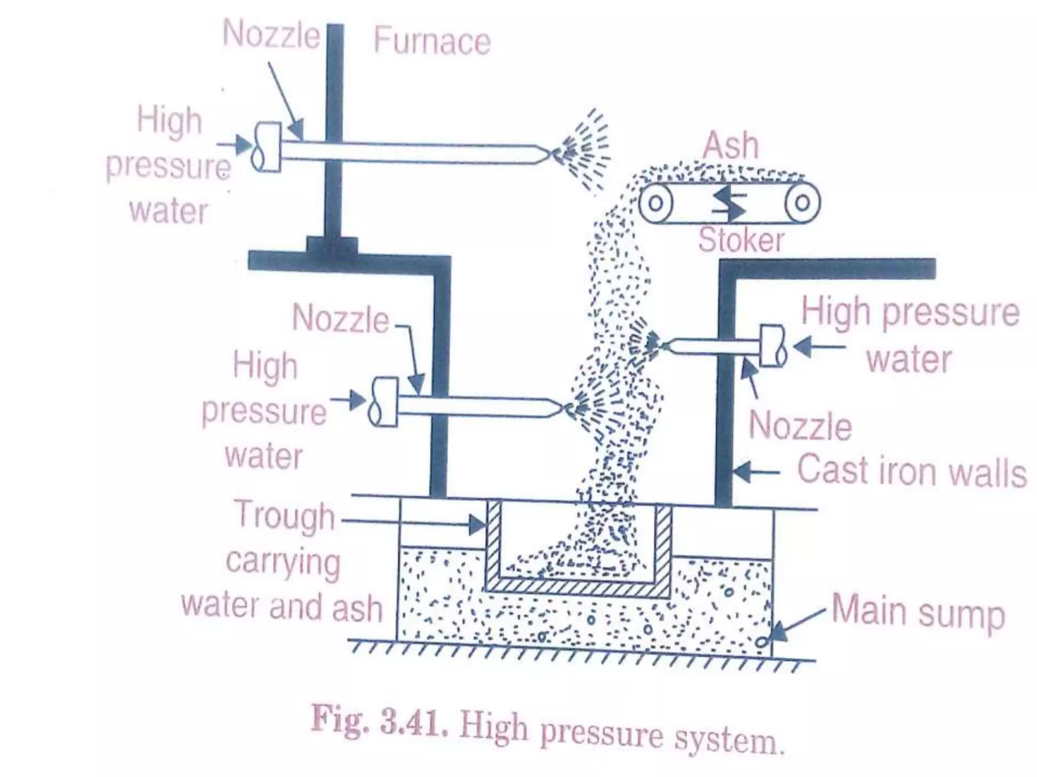
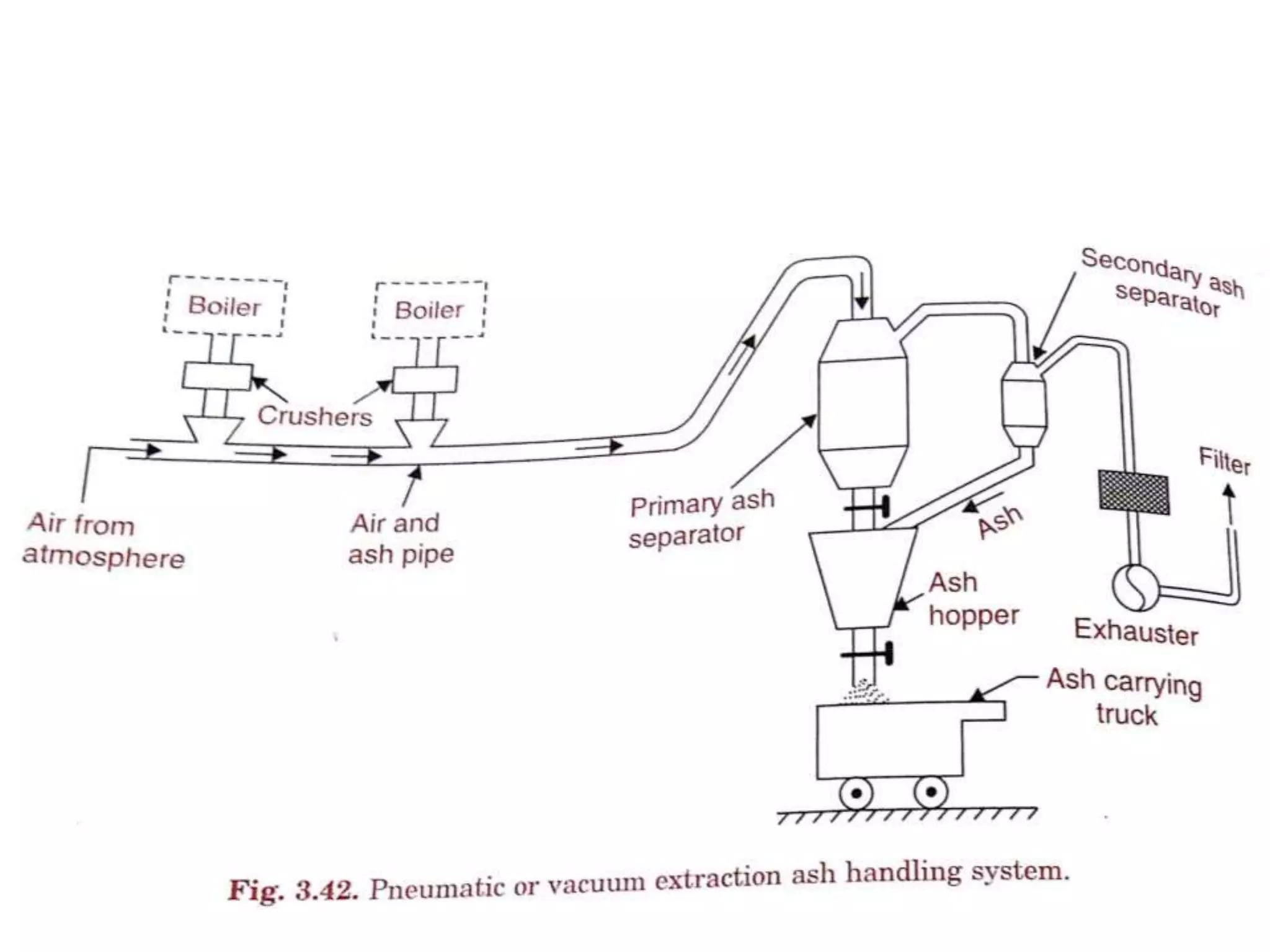
Coal based Thermal Power Plant
( Steam turbine Power Plant )
Steam turbine Power Plant
Layout of Steam (Thermal) Power Plant
Coal Based Thermal Power Plant
Four circuits in the PP
1. Fuel (coal) and ash circuit
2. Air and flue gas circuit
3. Feed water and steam flow circuit
4. Cooling water flow circuit
Coal and Ash Circuit
Coal and Ash circuit
• This includes coal delivery, preparation, coal handling,
boiler furnace, ash handling and ash storage.
• The coal from coal mines is delivered by ships, rail or by
trucks to the power station. This coal is sized by
crushers, breakers etc.
• The sized coal is then stored in coal storage (stock yard).
From the stock yard, the coal is transferred to the boiler
furnace by means of conveyors, elevators etc.
• The coal is burnt in the boiler furnace and ash is formed
by burning of coal, Ash coming out of the furnace will be
too hot, dusty and accompanied by some poisonous
gases.
Coal and Ash circuit
• The ash is transferred to ash storage. Usually, the
ash is quenched to reduced temperature
corrosion and dust content. There are different
methods employed for the disposal of ash.
• They are hydraulic system, water jetting, ash
sluice ways, pneumatic system etc. In large power
plants hydraulic system is used. In this system,
ash falls from furnace grate into high velocity
water stream. It is then carried to the slumps.
Working principle-Coal Circuit
• In a coal based thermal power plant, coal is
transported from coal mines to the generating
station.
• Generally, bituminous coal or brown coal is used as
fuel. The coal is stored in either 'dead storage' or in
'live storage'.
• Dead storage is generally 40 days backup coal storage
which is used when coal supply is unavailable. Live
storage is a raw coal bunker in boiler house.
• The coal is cleaned in a magnetic cleaner to filter out
if any iron particles are present which may cause
wear and tear in the equipment.
Working principle-Coal Circuit
• The coal from live storage is first crushed in
small particles and then taken into pulverized to
make it in powdered form.
• Fine powdered coal undergoes complete
combustion, and thus pulverized coal improves
efficiency of the boiler.
• The ash produced after the combustion of coal
is taken out of the boiler furnace and then
properly disposed.
• Periodic removal of ash from the boiler furnace
is necessary for the proper combustion.
Air and Flue Gas Circuit
Water and Steam circuit
• It consists of feed pump, economizer, boiler
drum, super heater, turbine condenser etc.
• Feed water is pumped to the economizer from
the hot well.
• This water is preheated by the flue gases in the
economizer.
• This preheated water is then supplied to the
boiler drum. Heat is transferred to the water by
the burning of coal. Due to this, water is
converted into steam
Water and Steam Circuit
Air and Flue gas circuit
• It consists of forced draught fan, air pre heater,
boiler furnace, super heater, economizer, dust
collector, induced draught fan, chimney etc. Air is
taken from the atmosphere by the action of a forced
draught fan.
• It is passed through an air pre-heater. The air is pre-
heated by the flue gases in the pre-heater. This pre-
heated air is supplied to the furnace to aid the
combustion of fuel. Due to combustion of fuel, hot
gases (flue gases) are formed
Air and Flue gas circuit
• The flue gases from the furnace pass over boiler
tubes and super heater tubes. (In boiler, wet steam
is generated and in super heater the wet steam is
superheated by the flue gases.)
• Then the flue gases pass through economizer to
heat the feed water. After that, it passes through
the air pre-heater to pre-heat the incoming air. It is
then passed through a dust catching device (dust
collector). Finally, it is exhausted to the atmosphere
through chimney.
Cooling Water Circuit
Cooling water circuit
• The circuit includes a pump, condenser, cooling
tower etc. the exhaust steam from the turbine is
condensed in condenser.
• In the condenser, cold water is circulated to
condense the steam into water. The steam is
condensed by losing its latent heat to the
circulating cold water
• Thus the circulating water is heated. This hot
water is then taken to a cooling tower, In cooling
tower, the water is sprayed in the form of
droplets through nozzles
Cooling water circuit
• The atmospheric air enters the cooling tower from the
openings provided at the bottom of the tower. This air
removes heat from water. Cooled water is collected in
a pond (known as cooling pond).
• This cold water is again circulated through the pump,
condenser and cooling tower. Thus the cycle is
repeated again and again. Some amount of water may
be lost during the circulation due to vaporization etc.
• Hence, make up water is added to the pond by means
of a pump. This water is obtained from a river or lake.
Advantages and Disadvantages of steam power plant
FBC Boilers
• Fluidization is a method of mixing fuel and air in a
specific proportion, for obtaining combustion.
• A fluidized bed is defined as the bed of solid
particles behaving as a fluid.
• If the distributed air is passed upward through a
finely divided bed of solid particles at low velocity.
• The velocity of air flow is steadily increased, a
stage is reached when the individual particles are
suspended in the air stream.
• If the air velocity is further increased, the bed
becomes highly turbulent and rapid mixing of
particles occur which appear like formation of
bubbles in a boiling liquid and the process of
combustion as a result is known as fluidized bed
combustion.
Types of FBC System
1. Atmospheric FBC System
a. Overfeed system
b. Underfeed system
2. Pressurized FBC System
Atmospheric FBC System
Pressurized FBC System
Commercial Layout of FBC system
Advantages of FBC Boiler
1.High thermal efficiency.
2.Easy ash removal system, to be transferred
for made cement.
3.Short commissioning and erection period.
4.Fully automated and thus ensures safe
operation, even at extreme temperatures.
5.Efficient operation at temperatures down to
150oC ( i.e. well below the ash fusion
temperature).
6.Reduced coal crushing etc. (pulverized coal is
not a necessity here).
7.The system can respond rapidly to
changes in load demand, due to quick
establishment of thermal equilibrium
between air and fuel particles in the bed.
8.The operation of fluidized bed furnace
at lower temperature helps in reducing
air pollution. The low temperature
operation also reduces the formation of
nitrogen oxides.
Disadvantages
• The fan power has to be maintained at a
considerably high value, since the air has
to be supplied continuously at a very high
pressure for supporting the bed.
• This in turn increases the operating cost
of the auxiliary units of the plant.
Steam Turbines
• Types Steam Turbine
Impulse Turbine
Reaction Turbine
Compounding of steam turbines is the method in which energy from the steam is
extracted in a number of stages rather than a single stage in a turbine. A compounded
steam turbine has multiple stages i.e. it has more than one set of nozzles and rotors, in
series, keyed to the shaft or fixed to the casing, so that either the steam pressure or
the jet velocity is absorbed by the turbine in number of stages.
1. Velocity Compounding of Impulse Turbine:
The velocity compounded impulse turbine has moving and fixed blades.
The moving blades are keyed to turbine shaft and fixed blades are fitted to casing.
The high pressure steam from boiler is expander in nozzle where pressure energy is
converted into kinetic energy.
2. Pressure Compounding of Impulse Turbine(Rateau turbine):
This is used to solve the problem of high blade velocity in the single-stage
impulse turbine.
It consists of alternate rings of nozzles and turbine blades. The nozzles are
fitted to the casing and the blades are keyed to the turbine shaft. In this type of
compounding, steam is expanded more than once(as in velocity compounding).
Condenser
Steam Condensers
Classification of condensers
• Jet Condensers
 Parallel flow type
Counter flow type
(i) Low level (ii) High level
 Ejector type
• Surface Condensers
(i) Down flow type
(ii) Central flow type
(iii)Inverted flow type
(iv) Regenerative type
(v) Evaporative type
Parallel flow –Low level jet condenser
Counter flow–Low level jet condenser
Counter flow –High level jet condenser
Ejector Condenser
Surface Condenser-Down flow type
Surface Condenser-Central flow type
Surface Condenser-Evaporative flow
Coal Unloading
• Preparation
– Breakers
– Crushers
– Sizers
– Dryers
– Magnetic separators
• Transfer
Belt conveyors Screw conveyors
Vee bucket elevator Pivoted bucket conveyors
Grab bucket conveyors Flight conveyors
Skip hosts Mass flow conveyors
Storage of coal
Draught System
• Types
Natural draught
Artificial draught
Mechanical Draught
 Forced Draught
 Induced Draught
Feed water treatment
Classification of impurities
Visible impurities
Microbiological growth
Turbidity and sediments
Dissolved gases
CO2,O2,N2,H2S
Minerals and salts
Fe, Mn, NaCl, KCl, Fluorides, Silica
 Mineral acids
Hardness
Causes of Impurities
Scale formation
Corrosion
Carryover
Embrittlement
Methods of Feed water treatment
1.Mechanical treatment
(i) Sedimentation (ii) Coagulation
(iii) Filtration (iv) Interior painting
2. Thermal treatment
(i) Deaeration
(ii) Distillation by evaporators
3. Chemical treatment
(i) Cold lime soda softening process
(ii) Hot lime soda softening process
(iii) Lime phosphate softening process
(iv) Ion exchange process
4. Demineralization
(i) Hot lime soda and hot zeolite process
(ii) Adding acid to control alkalinity and vice versa
5.Blow down
Mechanical treatment
Thermal treatment
Chemical Treatment
• Lime soda softening process
Hot process softening process
Ion Exchange process
• Sodium zeolite process
Hydrogen zeolite process
Demineralization
Binary Vapor Cycle
Topping Cycle
Cogeneration
Bottoming cycle Power plant
Rankine cycle
Rankine cycle improvisations
Effect of Operating Conditions on
Rankine Cycle Efficiency
The Rankine cycle efficiency can be improved by
• Increasing the average temperature at which
heat is supplied.
• Decreasing/reducing the temperature at
which heat is rejected
Rankine cycle improvisations
This can be achieved by making suitable changes in the conditions of steam
generation or condensation, as discussed below :
Increasing boiler pressure. It has been observed that by
increasing the boiler pressure (other factors remaining the
same) the cycle tends to rise and reaches a maximum value at
a boiler pressure of about 166 bar
Superheating. All other factors remaining the same, if the steam
is superheated before allowing it to expand the Rankine cycle
efficiency may be increased. The use of superheated steam
also ensures longer turbine blade life because of the absence
of erosion from high velocity water particles that are
suspended in wet vapour.
Reducing condenser pressure. The thermal efficiency of the
cycle can be amply improved by reducing the condenser
pressure (hence by reducing the temperature at which heat is
rejected), especially in high vacuums. But the increase in
efficiency is obtained at the increased cost of condensation
apparatus
Improvisations of Rankine Cycle
• Reheating
• Regeneration
• Combined reheating and regeneration
Steam is the working fluid in an ideal Rankine cycle with
superheat and reheat. Steam enters the first-stage
turbine at 8.0 MPa, 480ºC, and expands to 0.7 MPa. It is
then reheated to 440ºC before entering the second-
stage turbine, where it expands to the condenser
pressure of 0.008 MPa. The net power output is 100
MW. Determine
(a) the thermal efficiency of the cycle, (b) the mass flow
rate of steam, in kg/h, (c) the rate of heat transfer from
the condensing steam as it passes through the
condenser, in MW. Discuss the effects of reheat on the
vapor power cycle.
Rankine reheat cycle
• Starting at the inlet to the first turbine stage, the
pressure is 8.0 MPa and the temperature is
480°C, so the steam is a superheated vapor. h1=
3348.4 kJ/kg and s1= 6.6586 kJ/kg .K.
• State 2 is fixed by p2 = 0.7 MPa and s2 = s1 for the
isentropic expansion. Using saturated liquid and
saturated vapor data from table, the quality at
state 2 is
• The specific enthalpy is then ,
• State 3 is superheated vapor with p3 = 0.7 MPa and
T3 = 440o
C, so from table, h3 =3353.3 kJ/kg and s3 =
7.7571 kJ/kg .K.
• To fix state 4, use p4 = 0.008 MPa and s4 = s3 for the
isentropic expansion through the second-stage
turbine.
• The specific enthalpy is
• h4 = 173.88 + (0.9382)2403.1 = 2428.5 kJ/kg
• State 5 is saturated liquid at 0.008 MPa, so h5
=5173.88 kJ/kg. Finally, the state at the pump
exit h6 = 181.94 kJ/kg.
• The net power developed by the cycle is
Mass and energy rate balances for the two
turbine stages and the pump reduce to give,
respectively
• Where ṁ is the mass flow rate of the steam.
• The total rate of heat transfer to the working fluid
as it passes through the boiler–superheater and
reheater is
•
• Using these expressions, the thermal efficiency is
• The mass flow rate of the steam can be obtained by
• The rate of heat transfer from the condensing steam
to the cooling water is
Consider a regenerative vapor power cycle with one
open feed water heater. Steam enters the turbine at 8.0
MPa, 480°C and expands to 0.7 MPa, where some of
the steam is extracted and diverted to the open feed
water heater operating at 0.7 MPa. The remaining steam
expands through the second-stage turbine to the
condenser pressure of 0.008 MPa. Saturated liquid exits
the open feed water heater at 0.7 MPa. The isentropic
efficiency of each turbine stage is 85% and each pump
operates isentropic ally. If the net power output of the
cycle is 100 MW, determine
• (a) the thermal efficiency and (b) the mass flow rate
of steam entering the first turbine stage, in kg/h.
• In summary, h1 = 3348.4 kJ/kg, h2 = 2832.8 kJ/kg,
• s2 = 6.8606 kJ/kg . K, h4 = 173.88 kJ/kg.
• The specific enthalpy at state 3 can be determined
using the isentropic efficiency of the second-stage
turbine
• State 6 is saturated liquid at 0.7 MPa. Thus,
• h6 = 697.22 kJ/kg.
• Since the pumps operate isentropically.
The specific enthalpy values at states 5 and 7 can be
determined as
Applying mass and energy rate balances to a control
volume enclosing the open heater, we find the
fraction y of the flow extracted at state 2 from
• On the basis of a unit of mass passing through the
first-stage turbine, the total turbine work output is
Unit   1

Unit 1

  • 1.
    Coal based ThermalPower Plant ( Steam turbine Power Plant )
  • 2.
  • 3.
    Layout of Steam(Thermal) Power Plant
  • 4.
    Coal Based ThermalPower Plant
  • 6.
    Four circuits inthe PP 1. Fuel (coal) and ash circuit 2. Air and flue gas circuit 3. Feed water and steam flow circuit 4. Cooling water flow circuit
  • 7.
    Coal and AshCircuit
  • 8.
    Coal and Ashcircuit • This includes coal delivery, preparation, coal handling, boiler furnace, ash handling and ash storage. • The coal from coal mines is delivered by ships, rail or by trucks to the power station. This coal is sized by crushers, breakers etc. • The sized coal is then stored in coal storage (stock yard). From the stock yard, the coal is transferred to the boiler furnace by means of conveyors, elevators etc. • The coal is burnt in the boiler furnace and ash is formed by burning of coal, Ash coming out of the furnace will be too hot, dusty and accompanied by some poisonous gases.
  • 9.
    Coal and Ashcircuit • The ash is transferred to ash storage. Usually, the ash is quenched to reduced temperature corrosion and dust content. There are different methods employed for the disposal of ash. • They are hydraulic system, water jetting, ash sluice ways, pneumatic system etc. In large power plants hydraulic system is used. In this system, ash falls from furnace grate into high velocity water stream. It is then carried to the slumps.
  • 10.
    Working principle-Coal Circuit •In a coal based thermal power plant, coal is transported from coal mines to the generating station. • Generally, bituminous coal or brown coal is used as fuel. The coal is stored in either 'dead storage' or in 'live storage'. • Dead storage is generally 40 days backup coal storage which is used when coal supply is unavailable. Live storage is a raw coal bunker in boiler house. • The coal is cleaned in a magnetic cleaner to filter out if any iron particles are present which may cause wear and tear in the equipment.
  • 11.
    Working principle-Coal Circuit •The coal from live storage is first crushed in small particles and then taken into pulverized to make it in powdered form. • Fine powdered coal undergoes complete combustion, and thus pulverized coal improves efficiency of the boiler. • The ash produced after the combustion of coal is taken out of the boiler furnace and then properly disposed. • Periodic removal of ash from the boiler furnace is necessary for the proper combustion.
  • 12.
    Air and FlueGas Circuit
  • 13.
    Water and Steamcircuit • It consists of feed pump, economizer, boiler drum, super heater, turbine condenser etc. • Feed water is pumped to the economizer from the hot well. • This water is preheated by the flue gases in the economizer. • This preheated water is then supplied to the boiler drum. Heat is transferred to the water by the burning of coal. Due to this, water is converted into steam
  • 14.
  • 15.
    Air and Fluegas circuit • It consists of forced draught fan, air pre heater, boiler furnace, super heater, economizer, dust collector, induced draught fan, chimney etc. Air is taken from the atmosphere by the action of a forced draught fan. • It is passed through an air pre-heater. The air is pre- heated by the flue gases in the pre-heater. This pre- heated air is supplied to the furnace to aid the combustion of fuel. Due to combustion of fuel, hot gases (flue gases) are formed
  • 16.
    Air and Fluegas circuit • The flue gases from the furnace pass over boiler tubes and super heater tubes. (In boiler, wet steam is generated and in super heater the wet steam is superheated by the flue gases.) • Then the flue gases pass through economizer to heat the feed water. After that, it passes through the air pre-heater to pre-heat the incoming air. It is then passed through a dust catching device (dust collector). Finally, it is exhausted to the atmosphere through chimney.
  • 17.
  • 18.
    Cooling water circuit •The circuit includes a pump, condenser, cooling tower etc. the exhaust steam from the turbine is condensed in condenser. • In the condenser, cold water is circulated to condense the steam into water. The steam is condensed by losing its latent heat to the circulating cold water • Thus the circulating water is heated. This hot water is then taken to a cooling tower, In cooling tower, the water is sprayed in the form of droplets through nozzles
  • 19.
    Cooling water circuit •The atmospheric air enters the cooling tower from the openings provided at the bottom of the tower. This air removes heat from water. Cooled water is collected in a pond (known as cooling pond). • This cold water is again circulated through the pump, condenser and cooling tower. Thus the cycle is repeated again and again. Some amount of water may be lost during the circulation due to vaporization etc. • Hence, make up water is added to the pond by means of a pump. This water is obtained from a river or lake.
  • 20.
    Advantages and Disadvantagesof steam power plant
  • 26.
    FBC Boilers • Fluidizationis a method of mixing fuel and air in a specific proportion, for obtaining combustion. • A fluidized bed is defined as the bed of solid particles behaving as a fluid. • If the distributed air is passed upward through a finely divided bed of solid particles at low velocity. • The velocity of air flow is steadily increased, a stage is reached when the individual particles are suspended in the air stream. • If the air velocity is further increased, the bed becomes highly turbulent and rapid mixing of particles occur which appear like formation of bubbles in a boiling liquid and the process of combustion as a result is known as fluidized bed combustion.
  • 28.
    Types of FBCSystem 1. Atmospheric FBC System a. Overfeed system b. Underfeed system 2. Pressurized FBC System
  • 29.
  • 30.
  • 31.
  • 32.
    Advantages of FBCBoiler 1.High thermal efficiency. 2.Easy ash removal system, to be transferred for made cement. 3.Short commissioning and erection period. 4.Fully automated and thus ensures safe operation, even at extreme temperatures. 5.Efficient operation at temperatures down to 150oC ( i.e. well below the ash fusion temperature). 6.Reduced coal crushing etc. (pulverized coal is not a necessity here).
  • 33.
    7.The system canrespond rapidly to changes in load demand, due to quick establishment of thermal equilibrium between air and fuel particles in the bed. 8.The operation of fluidized bed furnace at lower temperature helps in reducing air pollution. The low temperature operation also reduces the formation of nitrogen oxides.
  • 34.
    Disadvantages • The fanpower has to be maintained at a considerably high value, since the air has to be supplied continuously at a very high pressure for supporting the bed. • This in turn increases the operating cost of the auxiliary units of the plant.
  • 35.
    Steam Turbines • TypesSteam Turbine Impulse Turbine Reaction Turbine
  • 40.
    Compounding of steamturbines is the method in which energy from the steam is extracted in a number of stages rather than a single stage in a turbine. A compounded steam turbine has multiple stages i.e. it has more than one set of nozzles and rotors, in series, keyed to the shaft or fixed to the casing, so that either the steam pressure or the jet velocity is absorbed by the turbine in number of stages. 1. Velocity Compounding of Impulse Turbine: The velocity compounded impulse turbine has moving and fixed blades. The moving blades are keyed to turbine shaft and fixed blades are fitted to casing. The high pressure steam from boiler is expander in nozzle where pressure energy is converted into kinetic energy. 2. Pressure Compounding of Impulse Turbine(Rateau turbine): This is used to solve the problem of high blade velocity in the single-stage impulse turbine. It consists of alternate rings of nozzles and turbine blades. The nozzles are fitted to the casing and the blades are keyed to the turbine shaft. In this type of compounding, steam is expanded more than once(as in velocity compounding).
  • 46.
  • 47.
  • 48.
    Classification of condensers •Jet Condensers  Parallel flow type Counter flow type (i) Low level (ii) High level  Ejector type • Surface Condensers (i) Down flow type (ii) Central flow type (iii)Inverted flow type (iv) Regenerative type (v) Evaporative type
  • 49.
    Parallel flow –Lowlevel jet condenser
  • 50.
  • 51.
    Counter flow –Highlevel jet condenser
  • 52.
  • 53.
  • 54.
  • 55.
  • 60.
  • 61.
    • Preparation – Breakers –Crushers – Sizers – Dryers – Magnetic separators • Transfer Belt conveyors Screw conveyors Vee bucket elevator Pivoted bucket conveyors Grab bucket conveyors Flight conveyors Skip hosts Mass flow conveyors
  • 68.
  • 76.
    Draught System • Types Naturaldraught Artificial draught Mechanical Draught  Forced Draught  Induced Draught
  • 80.
    Feed water treatment Classificationof impurities Visible impurities Microbiological growth Turbidity and sediments Dissolved gases CO2,O2,N2,H2S Minerals and salts Fe, Mn, NaCl, KCl, Fluorides, Silica  Mineral acids Hardness
  • 81.
    Causes of Impurities Scaleformation Corrosion Carryover Embrittlement
  • 82.
    Methods of Feedwater treatment 1.Mechanical treatment (i) Sedimentation (ii) Coagulation (iii) Filtration (iv) Interior painting 2. Thermal treatment (i) Deaeration (ii) Distillation by evaporators
  • 83.
    3. Chemical treatment (i)Cold lime soda softening process (ii) Hot lime soda softening process (iii) Lime phosphate softening process (iv) Ion exchange process 4. Demineralization (i) Hot lime soda and hot zeolite process (ii) Adding acid to control alkalinity and vice versa 5.Blow down
  • 84.
  • 85.
  • 86.
    Chemical Treatment • Limesoda softening process
  • 87.
  • 88.
    Ion Exchange process •Sodium zeolite process
  • 89.
  • 91.
  • 92.
  • 93.
  • 94.
  • 96.
  • 97.
  • 98.
    Rankine cycle improvisations Effectof Operating Conditions on Rankine Cycle Efficiency The Rankine cycle efficiency can be improved by • Increasing the average temperature at which heat is supplied. • Decreasing/reducing the temperature at which heat is rejected
  • 99.
    Rankine cycle improvisations Thiscan be achieved by making suitable changes in the conditions of steam generation or condensation, as discussed below : Increasing boiler pressure. It has been observed that by increasing the boiler pressure (other factors remaining the same) the cycle tends to rise and reaches a maximum value at a boiler pressure of about 166 bar Superheating. All other factors remaining the same, if the steam is superheated before allowing it to expand the Rankine cycle efficiency may be increased. The use of superheated steam also ensures longer turbine blade life because of the absence of erosion from high velocity water particles that are suspended in wet vapour. Reducing condenser pressure. The thermal efficiency of the cycle can be amply improved by reducing the condenser pressure (hence by reducing the temperature at which heat is rejected), especially in high vacuums. But the increase in efficiency is obtained at the increased cost of condensation apparatus
  • 100.
    Improvisations of RankineCycle • Reheating • Regeneration • Combined reheating and regeneration
  • 108.
    Steam is theworking fluid in an ideal Rankine cycle with superheat and reheat. Steam enters the first-stage turbine at 8.0 MPa, 480ºC, and expands to 0.7 MPa. It is then reheated to 440ºC before entering the second- stage turbine, where it expands to the condenser pressure of 0.008 MPa. The net power output is 100 MW. Determine (a) the thermal efficiency of the cycle, (b) the mass flow rate of steam, in kg/h, (c) the rate of heat transfer from the condensing steam as it passes through the condenser, in MW. Discuss the effects of reheat on the vapor power cycle. Rankine reheat cycle
  • 110.
    • Starting atthe inlet to the first turbine stage, the pressure is 8.0 MPa and the temperature is 480°C, so the steam is a superheated vapor. h1= 3348.4 kJ/kg and s1= 6.6586 kJ/kg .K. • State 2 is fixed by p2 = 0.7 MPa and s2 = s1 for the isentropic expansion. Using saturated liquid and saturated vapor data from table, the quality at state 2 is
  • 111.
    • The specificenthalpy is then , • State 3 is superheated vapor with p3 = 0.7 MPa and T3 = 440o C, so from table, h3 =3353.3 kJ/kg and s3 = 7.7571 kJ/kg .K. • To fix state 4, use p4 = 0.008 MPa and s4 = s3 for the isentropic expansion through the second-stage turbine.
  • 112.
    • The specificenthalpy is • h4 = 173.88 + (0.9382)2403.1 = 2428.5 kJ/kg • State 5 is saturated liquid at 0.008 MPa, so h5 =5173.88 kJ/kg. Finally, the state at the pump exit h6 = 181.94 kJ/kg. • The net power developed by the cycle is Mass and energy rate balances for the two turbine stages and the pump reduce to give, respectively
  • 113.
    • Where ṁis the mass flow rate of the steam. • The total rate of heat transfer to the working fluid as it passes through the boiler–superheater and reheater is •
  • 114.
    • Using theseexpressions, the thermal efficiency is • The mass flow rate of the steam can be obtained by
  • 115.
    • The rateof heat transfer from the condensing steam to the cooling water is
  • 116.
    Consider a regenerativevapor power cycle with one open feed water heater. Steam enters the turbine at 8.0 MPa, 480°C and expands to 0.7 MPa, where some of the steam is extracted and diverted to the open feed water heater operating at 0.7 MPa. The remaining steam expands through the second-stage turbine to the condenser pressure of 0.008 MPa. Saturated liquid exits the open feed water heater at 0.7 MPa. The isentropic efficiency of each turbine stage is 85% and each pump operates isentropic ally. If the net power output of the cycle is 100 MW, determine • (a) the thermal efficiency and (b) the mass flow rate of steam entering the first turbine stage, in kg/h.
  • 118.
    • In summary,h1 = 3348.4 kJ/kg, h2 = 2832.8 kJ/kg, • s2 = 6.8606 kJ/kg . K, h4 = 173.88 kJ/kg. • The specific enthalpy at state 3 can be determined using the isentropic efficiency of the second-stage turbine • State 6 is saturated liquid at 0.7 MPa. Thus, • h6 = 697.22 kJ/kg. • Since the pumps operate isentropically.
  • 119.
    The specific enthalpyvalues at states 5 and 7 can be determined as Applying mass and energy rate balances to a control volume enclosing the open heater, we find the fraction y of the flow extracted at state 2 from
  • 120.
    • On thebasis of a unit of mass passing through the first-stage turbine, the total turbine work output is