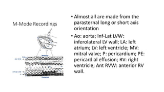
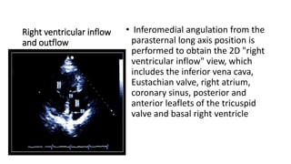
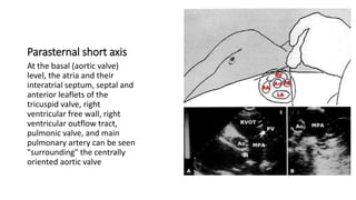
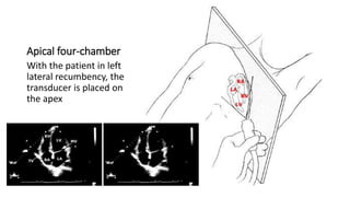
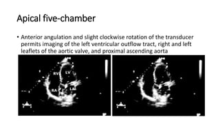
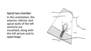
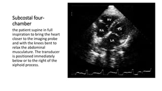
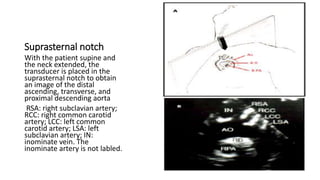
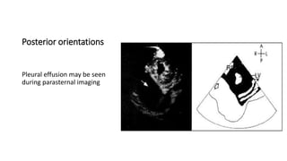
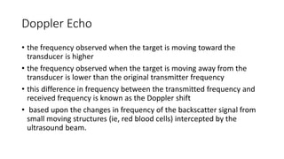
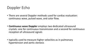
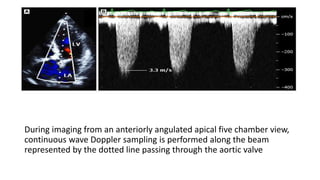
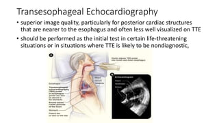
2. TTE
• Objectives: To review the nomenclature, standard protocol, and normal
views associated with TTE
• Two-dimensional (2D) echocardiography provides tomographic or "thin
slice" imaging.
• Transducer position is altered by placing the transducer at various locations
on the thorax
• view is manipulated by a combination of angulation and rotation.
3. Views
• Each tomographic view is defined by the transducer position
• Parasternal
• Apical
• Subcostal
• suprasternal
• long axis
• short axis
• four-chamber
• five-chamber
4.
5. Sequence
• fairly standard protocol for
transducer orientation, beginning
with parasternal views and
progressing to apical, subcostal,
and suprasternal positions
• Almost all imaging is performed
with the patient in the left lateral
decubitus position during quiet
respiration or extended expiration
6. Parasternal Long Axis
• transducer in the third or fourth left
intercostal space, immediately adjacent
to the sternum, a long axis view of the
heart is obtained that bisects the aortic
and mitral valve
• This parasternal long axis was obtained in
systole; the aortic valve is open and the
mitral is closed.
• RV: right ventricle; IL: inferolateral left
ventricular wall; IVS: interventricular
septum; NCC: noncoronary cusp of the
aortic valve; RCC: right coronary cusp of
the aortic valve; aML: anterior mitral
valve leaflet; pML: posterior mitral valve
leaftlet; dAo: descending aorta.
7. M-Mode Recordings
• Almost all are made from the
parasternal long or short axis
orientation
• Ao: aorta; Inf-Lat LVW:
inferolateral LV wall; LA: left
atrium; LV: left ventricle; MV:
mitral valve; P: pericardium; PE:
pericardial effusion; RV: right
ventricle; Ant RVW: anterior RV
wall.
8. Right ventricular inflow
and outflow
• Inferomedial angulation from the
parasternal long axis position is
performed to obtain the 2D "right
ventricular inflow" view, which
includes the inferior vena cava,
Eustachian valve, right atrium,
coronary sinus, posterior and
anterior leaflets of the tricuspid
valve and basal right ventricle
9. Parasternal short axis
At the basal (aortic valve)
level, the atria and their
interatrial septum, septal and
anterior leaflets of the
tricuspid valve, right
ventricular free wall, right
ventricular outflow tract,
pulmonic valve, and main
pulmonary artery can be seen
"surrounding" the centrally
oriented aortic valve
11. Apical five-chamber
• Anterior angulation and slight clockwise rotation of the transducer
permits imaging of the left ventricular outflow tract, right and left
leaflets of the aortic valve, and proximal ascending aorta
12. Apical two-chamber
In this orientation, the
anterior, inferior, and
apical walls of the left
ventricle are
visualized, along with
the left atrium and its
appendage.
13. Subcostal four-
chamber
the patient supine in full
inspiration to bring the heart
closer to the imaging probe
and with the knees bent to
relax the abdominal
musculature. The transducer
is positioned immediately
below or to the right of the
xiphoid process.
14. Suprasternal notch
With the patient supine and
the neck extended, the
transducer is placed in the
suprasternal notch to obtain
an image of the distal
ascending, transverse, and
proximal descending aorta
RSA: right subclavian artery;
RCC: right common carotid
artery; LCC: left common
carotid artery; LSA: left
subclavian artery; IN:
inominate vein. The
inominate artery is not labled.
17. Doppler Echo
• the frequency observed when the target is moving toward the
transducer is higher
• the frequency observed when the target is moving away from the
transducer is lower than the original transmitter frequency
• this difference in frequency between the transmitted frequency and
received frequency is known as the Doppler shift
• based upon the changes in frequency of the backscatter signal from
small moving structures (ie, red blood cells) intercepted by the
ultrasound beam.
18.
19. Doppler Echo
• There are several Doppler methods used for cardiac evaluation:
continuous wave, pulsed wave, and color flow.
• Continuous wave Doppler employs two dedicated ultrasound
crystals: one for continuous transmission and a second for continuous
reception of ultrasound signals
• typically used to measure higher velocities as in pulmonary
hypertension and aortic stenosis
20. During imaging from an anteriorly angulated apical five chamber view,
continuous wave Doppler sampling is performed along the beam
represented by the dotted line passing through the aortic valve
21. Pulsed Doppler
• permits sampling of local blood flow velocities at a specific region (or
sample volume).
• useful for assessing the relatively low velocity flows associated with
mitral or tricuspid inflow, pulmonary venous flow, left atrial
appendage flow, left ventricular outflow, or right ventricular outflow
blood flows
• an ultrasound pulse is transmitted and then the receiver "listens"
during a subsequent interval defined by the distance from the
transmitter and the sample site
22. • anteriorly angulated apical five chamber echocardiographic view
(panel A).
• The arrow indicates the position of the sample volume in the LVOT.
The signal in panel B-the Doppler profile (blue dotted line), the VTI of
the LV outflow can be obtained. The VTI reflects the distance that the
column of blood travels through the LVOT during systole (also called
stroke distance), and can be used to compute LV stroke volume by
multiplying the LVOT VTI by the cross sectional area of the LVOT.
23. Colour Flow Doppler
• with flow toward the transducer typically displayed in orange/red and
flow away from the transducer displayed as blue.
• the variance of velocities within jets is usually color coded as a
multicolored mosaic display
• The outflow tract is completely occupied by the aortic regurgitant
color flow jet (AR jet); when the jet exceeds 65 percent of the left
ventricular outflow tract (LVOT) width, the regurgitation is judged
severe.
24. 3D ECHO
• allows for rapid acquisition of images and datasets during a single
breath-hold without the need for off-line reconstruction.
• improved accuracy of evaluation of cardiac chamber volumes and
more realistic visualization of cardiac valves and congenital
abnormalities.
• Principal reasons for requesting an echocardiogram in clinical practice
include the assessment of left ventricular (LV) chamber size and
systolic function.
• provides the most detailed anatomic and functional information
when planning a variety of interventions and evaluating their results.
• limited by its less than optimal frame rates and spatial and temporal
resolution.
25. Transesophageal Echocardiography
• superior image quality, particularly for posterior cardiac structures
that are nearer to the esophagus and often less well visualized on TTE
• should be performed as the initial test in certain life-threatening
situations or in situations where TTE is likely to be nondiagnostic,
26. Indications of TEE
• Suspected acute aortic pathology (ie, dissection, transsection,
intramural hematoma)
• •Suspected prosthetic valve dysfunction
• •Suspected complications of endocarditis (eg, fistula, abscess)
• •Evaluation for left atrial/left atrial appendage thrombus in a patient
with atrial fibrillation/atrial flutter to facilitate clinical decision making
regarding anticoagulation, cardioversion, or ablation
• •Evaluation of source of embolism in a young patient for whom a TEE
would be performed if the TTE was normal
27. Contraindication of TEE
• patients with altered mental status
• tenuous cardiorespiratory status
• recent or active esophageal tear or haemorrhage
• coagulopathies, thrombocytopenia
• esophageal stricture, Zenker's diverticulum
• severe cervical spine arthritis with reduced range of motion