Download to read offline
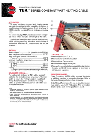
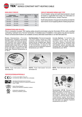

The document describes TEK series constant watt heating cables. It specifies the cable construction which includes heating conductors, dielectric and protective jackets. It also describes the required basic accessories like terminators and end-of-circuit terminations. The cable is used for circuit lengths up to 3658 meters and provides consistent watt-per-foot power output along its length. It lists ratings for the cable including voltage, temperature limits and bend radii. Certifications are also provided.


