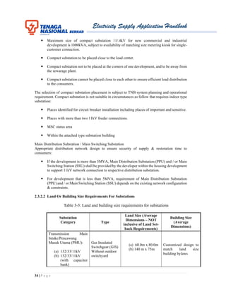
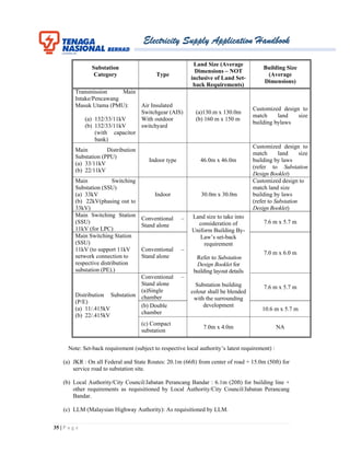
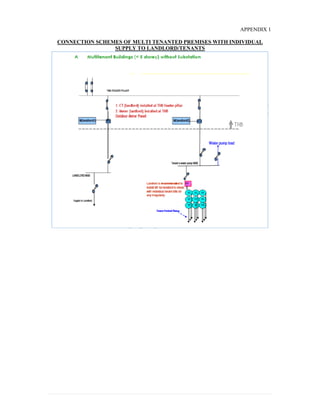
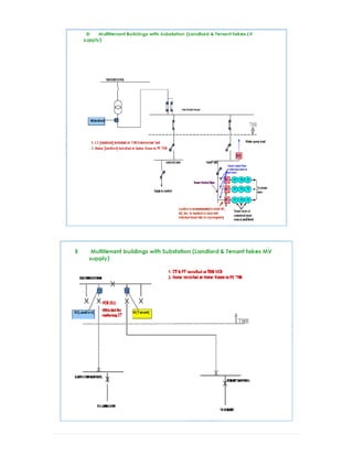
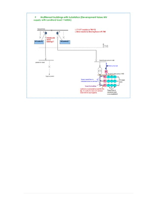
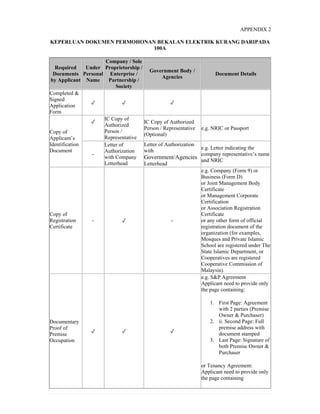
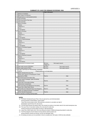
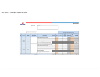
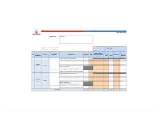
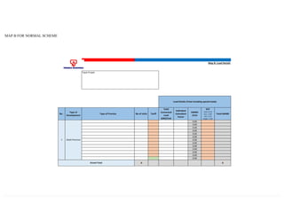
1 | P a g e
Vision
To be among the leading corporations
in energy and related businesses globally
Mission
We are committed to excellence
in our products and services
Shared values
Our share values provide us with
a principle that will shape our
business ethics and operations
 Customer first
 Business excellence
 Integrity
 Caring
2 | P a g e
Acknowledgement
Tenaga Nasional Berhad would like to acknowledge those that have
actively contributed towards this effort in revisiting the TNB's Electricity
Supply Application Handbook initially launched in 2001 and its
subsequent Second (2nd
) Edition in 2007.
In our endeavor to provide more effective and efficient service to our
customers, your inputs have been of tremendous help to us to further
improve and add more substance to the Third (3rd
) Edition.
Special thanks to Federation of Malaysia Consumers Association
(FOMCA), Federation of Malaysian Manufacturers (FMM), Association
of Consulting Engineers of Malaysia (ACEM) , The Electrical and
Electronics Association of Malaysia (TEEAM), Real Estate and Housing
Developers’ Association (REHDA), The Institution of Engineers,
Malaysia (IEM), Masters Builders Association of Malaysia (MBAM),
The Cement & Concrete Association of Malaysia (C&CA), Suruhanjaya
Tenaga, Kementerian Tenaga, Teknologi Hijau dan Air (KETTHA),
Kementerian Perumahan dan Kerajaan Tempatan (KPKT), Kementerian
Kemajuan Luar Bandar dan Wilayah (KKLW) dan Jabatan Kerja Raya
(JKR) for their comments and all others that have contributed in more
ways than one to the publication of the 3rd
Edition of the Electricity
Supply Application Handbook.
Electricity Supply Application Handbook
3 | P a g e
ELECTRICITY SUPPLY APPLICATION HANDBOOK
CONTENT
1.0 SUPPLY APPLICATION
1.1.0 Tenaga Nasional Berhad Electricity System.............................................................5
1.2.0 Supply Application for Load up to 100A ...............................................................11
1.3.0 Supply Application for Load Exceeding 100A.......................................................13
1.4.0 Application Process for Streetlight.........................................................................20
2.0 CONNECTION GUIDELINES
2.1.0 Planning and Design Criteria..................................................................................22
2.2.0 Demand Estimation.................................................................................................28
2.3.0 Supply Schemes......................................................................................................31
2.4.0 Connection Guideline For Embedded/Distributed Generators………………...……38
3.0 METERING GUIDELINES
3.1.0 General Requirements.............................................................................................41
3.2.0 Single Phase Metering ............................................................................................43
3.3.0 Three Phase Whole Current Metering ....................................................................46
3.4.0 Group Metering For Whole Current Metering........................................................47
3.5.0 LV CT Metering .....................................................................................................49
3.6.0 Medium Voltage And High Voltage Metering .......................................................51
4.0 GLOSSARY AND DEFINITIONS ...........................................................................56
5.0 APPENDICES.............................................................................................................62
_________________________________________________________________________
Electricity Supply Application Handbook
4 | P a g e
1.0 SUPPLY APPLICATION
CONTENT
1.1.0 TENAGA NASIONAL BERHAD ELECTRICITY SYSTEM....................................... 5
1.1.1 Introduction......................................................................................................................... 5
1.1.2 Distribution Network Division and Retail Division.............................................................. 5
1.1.3 Kedai Tenaga ........................................................................................................................ 5
1.1.4 Electrical System .................................................................................................................. 6
1.1.5 Types of Supply ................................................................................................................... 8
1.1.6 Charges……………………………………………………………………………………..10
1.1.7 Service Level Agreement (SLA) ....................................................................................... 10
1.2.0 SUPPLY APPLICATION FOR LOAD UP TO 100A ................................................... 11
1.2.1 Purpose................................................................................................................................ 11
1.2.2 What Is The Steps Involved To Get Your Electricity......................................................... 11
1.2.3 TNB Supply Lead Time...................................................................................................... 12
1.2.4 Dispute Between Applicant and The Electrical Contractor ................................................ 12
1.3.0 SUPPLY APPLICATION FOR LOAD EXCEEDING 100A ....................................... 13
1.3.1 Purpose................................................................................................................................ 13
1.3.2 Application Process ............................................................................................................ 13
1.3.3 Application Parts................................................................................................................. 13
Part A : Authorities Approval Process............................................................................... 13
Part B : TNB Application Process (Technical & Financial Approval Process)................. 15
1.3.4 What The Applicant Should Do.......................................................................................... 16
1.3.5 Supply Project Lead Time................................................................................................... 17
1.3.6 What The Electrical Consultant Engineer Should Do......................................................... 18
1.3.7 Dispute Between Applicant and Electrical Consultant Engineer........................................ 19
1.4.0 APPLICATION PROCESS FOR STREETLIGHT...................................................... 20
1.4.1 Purpose................................................................................................................................ 20
1.4.2 Types of Applications......................................................................................................... 20
1.4.3 Application by Developer................................................................................................... 20
1.4.4 Application by Individuals/ Local Authority/Government Authority................................. 20
Electricity Supply Application Handbook
5 | P a g e
1.1.0 TENAGA NASIONAL BERHAD ELECTRICITY SYSTEM
1.1.1 Introduction
The Tenaga Nasional Berhad (TNB), a public listed company registered under Companies
Act 1965, is charged with the following responsibilities:
 To generate, transmit, distribute and sell energy to consumer throughout Peninsular
Malaysia.
 To plan, install, operate and maintain electricity installation for the generation,
transmission and distribution of electricity.
To achieve the above objectives, the company owns and operate power plants and the
National Grid and installed for this purpose are consumer service centres, call management
centres, substations and administrative offices throughout Peninsular Malaysia. TNB’s core
activities are in generation, transmission and distribution of electricity which are being
handled by four divisions :
 Generation Division
 Transmission Division
 Distribution Network Division
 Retail Division
1.1.2 Distribution Network Division and Retail Division
Distribution Network Division and Retail Division supply electricity in strict accordance
with the provisions of the TNB Licence, Electricity Supply Act 1990, the Licensee Supply
Regulations 1990 and the Electricity Regulations 1994 (and all amendments thereto).
Distribution Network Division is responsible for the upstream network operations which
involves planning, designing, constructing, operating and maintaining the system that
delivers electricity supply to the customers. Retail Division is responsible for the
downstream retail operations conducted through a network of 14 states which involves
marketing and selling electricity, connection of new supply, providing counter services
through Retail Outlets (Kedai Tenaga), collecting revenues, operating Call Management
Centres (TNB Careline 15454), handling customer enquiries or complaints and nurturing
strong customer and government relationship.
Kedai Tenaga provides functions pertaining to Application for Electricity Supply, Billing &
Collection, Upgrading of Services and other consumer related activities. Besides Kedai
Tenaga, consumer can also opt for online services through myTNB Portal.
1.1.3 Kedai Tenaga
Kedai Tenaga is TNB’s Service and Advisory Centre which are located throughout
Peninsular Malaysia. Complete information on Kedai Tenaga throughout Peninsular
Malaysia can be obtained via TNB website (www.tnb.com.my). This list is subject to
changes and may be reviewed from time to time.
Electricity Supply Application Handbook
6 | P a g e
Services provided at Kedai Tenaga include:
a) One stop payment counter for all electricity bills.
 Payment can be made by cash, cheque, credit card or debit card.
 You can also make arrangements to have your electricity bills paid
through banks or ATM cards.
 TNB, being a caring company, shall facilitate and make special arrangement
on case to case basis for the payment of bills for elderly and handicapped
consumers.
b) Electricity supply application
 At Kedai Tenaga, we offer you advice on all matters pertaining to your
electricity supply application.
 For wiring purposes in your premise, you may choose from a varied
selection of contractors from our directory of registered electrical
contractors.
c) Inquiries pertaining to billing and other related services.
 Kedai Tenaga shall provide clarification on any billing inquiries and its
related services to consumers.
 Appointments can be made to have the meter read in case the premises are
locked during working hours.
 Testing of meters can be carried out if consumers suspect that the meter is
faulty. A fee will be charge for such testing.
1.1.4 Electrical System
1.1.4.1 Voltages
The transmission voltage networks are 500kV, 275kV and 132kV, whilst the distribution
voltages are 33kV, 11kV and 400/230 Volts. However, in the case of certain parts of Johor
& Perak the distribution voltages may include 22kV and 6.6kV.
1.1.4.2 Supply Frequency
The supply frequency is 50Hz  1%.
1.1.4.3 Power Factor
Consumers are required to maintain their load power factor to a minimum of 0.85 for
voltage level less than 132kV and 0.90 for voltage level 132kV and above.
1.1.4.4 Earthing System
High Voltage and Extra High Voltage
• 3 phase configuration
• Solidly earthed
• Overhead lines and underground cable are used extensively for high and extra high
voltage distribution
Electricity Supply Application Handbook
7 | P a g e
Medium Voltage
• 3 phase configuration
• Impedance-earth (NER)
• Overhead lines and underground cable are used extensively for medium voltage
distribution
Low Voltage 400/230V
• 3 phase 4 wire system
• Neutral point solidly earthed mixture of overhead lines, underground cables and
aerial insulated cables
• Mixture of overhead lines, underground cables and aerial insulated cables
1.1.4.5 Short Circuit Ratings
All equipment proposed to be installed and connected to TNB supply must comply
with the following short circuit ratings:
System Short circuit rating
i. 500kV 50 kA, 1s
ii. 275kV
40 kA, 3s for bulk station
(50kA , 1s for Power Substation and 275kV
within 500kV substation)
iii. 132kV
31.5 kA, 3s
(40kA, 3s for substation adjacent to Power
Station, or within 500/275kV substation)
iv. 33kV 25 kA, 3s
v. 22kV 20 kA, 3s
vi. 11kV 20 kA, 3s
vii. 6.6kV 20 kA, 3s
viii. 400/230 V 31.5 kA, 3s
1.1.4.6 Act, Regulation and Customer Charter
The electricity supply and installation practice in Peninsular Malaysia are governed by the
following:-
1 Electricity Supply Act 1990 – Act 447
2 Licensee Supply Regulations 1990
3 Electricity Regulations 1994
4 Customer Charter – refer to TNB website (www.tnb.com.my)
1.1.4.7 Supply Voltage Options
Supply may be provided at any of the declared voltages :-
275 kV, 132kV, 33kV, 22 kV*, 11kV, 6.6 kV* and 400/230V. Generally, supplies to
domestic premises are given at single phase 2-wire or three phase 4-wire while for non
domestic premises the supply are at three phase 3-wire or three phase 4-wire. However, the
Electricity Supply Application Handbook
8 | P a g e
actual supply voltage provided depends on the individual applicant’s load requirements
(refer to Connection Guideline clause 3.1 – Maximum Demand levels and supply scheme):-
It should be noted that voltages other than the above classifications is not provided by TNB.
However, consumers can make their own transformation arrangements where necessary.
 System for certain parts of Johor and Perak only.
1.1.5 Types of Supply
1.1.5.1 Supply Application Based on Load
All new applications and upgrade of supply requirement can be classified into two (2) types
of supply applications.
a) Supply Application For Load Up To 100 A
 Supply from existing supply mains or
 Establishment of new supply mains or
 Establishment of new substation/substations
 Submission of applications to TNB by Electrical Contractor registered with the
Energy Commission
b) Supply Application For Load Exceeding 100 A
 Supply from existing supply mains or
 Establishment of new supply mains or
 Establishment of new substation/substations
 Submission of applications to TNB by Electrical Consultant Engineer registered
with the Board of Engineers Malaysia
Note: Establishment of new supply system may require the construction of a new
substation/substations and its related ancillaries.
1.1.5.2 Consumers Standby Supply
Standby generator(s) may be used by the applicant at their premises, subject to compliance
with the relevant laws. The generators shall remain a separate system from TNB distribution
system and the applicant shall declare to TNB on the safe installation of the generator(s).
This may be used in place of TNB’s supply source through a suitable, approved changeover
facility. The Energy Commission and other relevant authorities govern the usage of
generators and standby supply.
1.1.5.3 Alternative Source of Supply
A large consumer may require an alternative source of supply. TNB will provide such
alternative supply at an additional cost fully borne by the consumer.
Electricity Supply Application Handbook
9 | P a g e
1.1.5.4 Provision Of Temporary Supply
Application for a Temporary Supply means the electricity supply required is for a non-
permanent installation intended for a limited time. When a consumer is requesting for a
permanent supply, but a planned supply source is not available at that point of time and
temporary connection from another source of supply is constructed, the case is not
considered as a Temporary Supply.
Examples of Temporary Supply are, but not limited to, festivals or exhibition sites, circuses
and construction sites (inclusive of the worker's quarters).
Tariff for Temporary Supply shall be determined based on the usage of the Temporary
Supply premise. For example, Tariff A is for the worker's quarters on construction site,
Tariff B, C1 or C2 for construction site, festivals, exhibitions or circuses. A surcharge of
33% of the total bill, shall be charged monthly through out the Temporary Supply term.
The consumer is responsible to construct the respective infrastructure and TNB shall charge
the cost of connection and termination of cables. However in isolated cases where the
consumer does not have the ability and resources to construct the infrastructure, TNB may
provide such service and hence the Connection Charge shall be revised accordingly to
include the overall cost of constructing and dismantling. The Connection Charge monies
however shall be refunded based on the net book value amount of the returned installations
after the Temporary Supply has been dismantled.
1.1.5.5 Single Tenant Premises
If the supply is for a single tenant only then the entire supply will be metered at the
applicant’s incoming switchboard. The consumption will be charged at the appropriate tariff
rates.
1.1.5.6 Multi Tenanted Premises
For multi-tenanted domestic and commercial premises, the owner / developer shall have
the option of taking supply via bulk supply or individual supply to landlord and tenants
respectively.
(a) If taking bulk supply, the owner / developer of the multi tenanted premises must obtain
public distribution license (PDL) from Energy Commission. Copy of provisional
public distribution licence (PDL) must be appended during submission for TNB’s
technical comment on development plan and supply application. Copy of official
public distribution license (PDL) must be submitted to TNB during Special Electricity
Supply Agreement signatory stage before commencement of electrical infrastructure
work.
(b) In the event of premature termination or expiration of PDL where TNB is required to
take over the corresponding PDL supply area by Energy Commission, PDL holder is
responsible to ensure connection schemes and meter locations of landlord / tenants
are complying to TNB requirement, as described in the Connection Schemes of Multi
Tenanted Premises with individual supply to landlord / tenants in Appendix 1. All cost
incurred to be fully borne by PDL holder.
Electricity Supply Application Handbook
10 | P a g e
(c) If taking individual supply, the owner / developer is responsible to ensure connection
schemes and meter locations of landlord / tenants are complying to TNB requirement,
as described in the Connection Schemes of Multi Tenanted Premises with individual
supply to landlord/tenants in Appendix 1.
The design, installation and operating of such electrical system shall comply with
requirements of all the relevant authorities including the Energy Commission’s and
TNB’s.
1.1.5.7 Turnkey Projects
In certain cases, the applicant may apply to undertake the planning and installation of the
electrical systems (including overhead lines, switchgears, cables, according to TNB’s
specifications and requirements) with the assistance of Electrical Consultant Engineer(s) and
Electrical Contractor(s). Under the ‘turnkey’ concept the applicant will then hand over the
entire electrical system to TNB. TNB shall have the absolute discretion in deciding whether
the turnkey project to be carried out by the applicant.
1.1.6 Charges
1.1.6.1 Connection Charges
Please refer to the Statement of Connection Charges booklet available at TNB’s website
(www.tnb.com.my). The booklet is subjected to change as may be published from time to
time.
1.1.6.2 Tariff
Please refer to the Tariff booklet available at TNB’s website (www.tnb.com.my). Tariffs are
subjected to change as may be published from time to time and approved by the Ministry of
Energy, Science, Technology, Environment and Climate Change.
1.1.6.3 Request For Additional Requirement Or Special Features
The applicant shall bear the full cost for any request of additional requirements or special
features made by the applicant and/or impose by Local Authority. Please refer to the
Statement of Connection Charges booklet available at TNB’s website
(www.tnb.com.my). The booklet is subject to change as may be published from time to
time.
1.1.7 SERVICE LEVEL AGREEMENT (SLA)
1.1.7.1 SLA with Housing Developers
Offer is open to all housing developers to enter into a Service Level Agreement (SLA) with
TNB when applying for electricity supply for housing development (as prescribed under the
Housing Development (Control and Licensing) Act 1966). The scope of the SLA includes
the time frame process for connection of supply and the duties and obligation by TNB and
housing developers in ensuring the electricity supply is connected to the housing projects
within the stipulated time to avoid delays in handing over houses to the purchaser.
Electricity Supply Application Handbook
11 | P a g e
1.2.0 ELECTRICITY SUPPLY APPLICATION FOR LOAD UP TO
100A
1.2.1 Purpose
The application for the supply of electricity with load up to 100A which is for a single (1)
phase and three (3) phase low voltage system is outlined here.
1.2.2 What Is The Steps Involved To Get Your Electricity
The following steps are required to get the supply of electricity up to 100A for a single (1)
phase and three (3) phase low voltage system.
Steps Action Reference
1 Appointment of an Electrical Contractor
Appoint an Electrical Contractor who will act on
behalf and submit the electricity supply
application through myTNB portal.
For Move-In into existing premise (with no change
in electricity load) or Change of Tenancy, the
applicant shall skip Step 1.
Visit our online
application page at
https://www.mytnb.com.
my/
2 Complete All Required Documents
The Applicant or the appointed contractor
complete the electricity application form and attach
together the required documents. The applicant
shall sign the application form with TNB.
For online application, this step shall be done
accordingly as explained by the guidelines
available at the website.
Visit TNB’s online
application page at
https://www.mytnb.com.
my/
Appendix 2 – Required
Documents Checklist
3 Pay Essential Charges
Required initial payments (i.e. Connection Charge,
Security Deposit and Stamp Duty) related to the
application can be paid at Kedai Tenaga or online
through myTNB portal.
4 Get Electricity Supply
TNB installs meter and connects the electricity
supply once all the required payment is received.
Electricity Supply Application Handbook
12 | P a g e
1.2.3 TNB Supply Lead Time
TNB supply lead-time will be based on TNB’s Customer Charter as mention in TNB’s
website (www.tnb.com.my).
1.2.4 Dispute Between Applicant And The Electrical Contractor
In the event of a dispute between the applicant and the Electrical Contractor and the applicant
wishes to terminate the services of the Electrical Contractor, the applicant shall duly notify
the Electrical Contractor concerned in writing with the copy extended to TNB. TNB shall
not be a party to any dispute or litigation arising thereof.
Electricity Supply Application Handbook
13 | P a g e
1.3.0 ELECTRICITY SUPPLY APPLICATION FOR LOAD
EXCEEDING 100A
1.3.1 Purpose
The application for the supply of electricity for load exceeding 100A is outlined here.
1.3.2 Application Process
The application process incorporates not only TNB requirements but taking into account the
Government Development Plan Approval Process in Peninsular Malaysia issued by the
Bahagian Perancangan Dasar & Pembangunan Kementerian Perumahan dan Kerajaan
Tempatan.
The inclusion of the said Government procedure shall ensure :
 Infrastructure planning and approval process of the TNB complements the National
Policy
 TNB as a member Agency of the Government Development Plan Committee has to
ensure complete transparency of its process through timely responses to Development
Plan Approval Process
 TNB Supply Application Process ensures complete agreement of Distribution
Division’s plans and the Consultant Engineers submissions especially on the location
and size of substations needed for the supply of electricity to the development area, and
is valid for 2 years after the approval from the relevant Local Authority.
1.3.3 Application Parts
There are two parts to the application:
Part Function
A Authorities Approval Process
B
TNB Application Process (Technical & Financial Approval
(After completion of Part A)
PART A: Authorities Approval Process
The part A process approval that involves TNB’s technical comments is as shown in
Development Plan Approval Process Flowchart in Appendix 3. At each application process,
TNB requires a processing time of up to 14 days to complete the comments for the relevant
Local Authority. The main process can be summarised as follows:
Electricity Supply Application Handbook
14 | P a g e
Stage Description
1 Submission Development Plan
The Developer / Owner / Consultant Engineer submit development plan
application for the proposed development to Local Authority / One Stop Centre
(OSC).
All plans must be prepared by the party authorised by Local Authority.
Applicant must adhere to the requirements stipulated in the Development Plan
Checklist (checklist available in http://jky.kpkt.gov.my) during the submission of
Development Plan to Local Authority / One Stop Centre (OSC).
The comments from all relevant technical agencies including TNB are required
prior to approval by Local Authority / One Stop Centre.
2 TNB Register Application
The local authority / One Stop Centre submits application to TNB complete with
required details as in Development Plan Checklist TNB will:
 Acknowledge receipt and register development order plan in
Development Order Comment Book.
Study the proposal. Match the existing system network and determine method of
electricity supply.
3 Mutual Understanding Of Plan
Both TNB and Consultant Engineer will conduct discussion to agree to technical
requirement such as substation number, size, location, site and consumers main
switch room, etc.
In case of a dispute on TNB proposal, the Consultant Engineer shall refer to the
relevant State General Managers. A discussion shall be arranged by the relevant
State General Managers to arrive at an agreement.
4 TNB Submit Comments to Local Authority / One Stop Centre
TNB submit to Local Authority / One Stop Centre the proposed development
plans including all technical comments using TNB official stamp as required by
Local Authority.
Local Authority approves the proposed development plan. The validity is
subjected to:
- confirmation of layout details and pre-computation plans
- no changes in development
- 2 years extension or subject to respective Local Authority Development
Order Plan validity requirement
5 TNB Application for Electricity Supply above 100A process starts
(Part B)
Electricity Supply Application Handbook
15 | P a g e
PART B: TNB Application Process (Technical & Financial Approval)
Part B process is the TNB Application Process for Electricity Supply above 100 A as
outlined in the table below. The process starts after the completion of Part A (Authorities
Approval Process). The Process in Part B can be summarised as follows:
Stage Description
1 Submit Application
The Electrical Consultant Engineer (registered with Board of Engineers Malaysia)
on behalf of the developer/consumer submits application for the Electricity Supply
Application through myTNB portal and TNB Distribution Network Division Local
Office. Complete details as in Appendix 4 must be submitted with the application.
TNB will issue an acknowledgement letter to the Electrical Consultant Engineer.
2 Documentation Check And System Study
TNB will check on the documentation and carry out system studies and shall advise
on the necessary amendments (if any) to the consultant by letter. The Electrical
Consultant Engineer is to ensure that all the amendments are done and resubmitted
to TNB.
3 Joint Meeting
TNB will restudy the amendments and arrange for a joint meeting with the Electrical
Consultant Engineer and Applicant for final acceptance of the technical
requirements including substation details, cable/overhead line route, metering
system requirements and meter location. Activities of both parties will be recorded
in the Joint Meeting Action Log. TNB shall forward in writing the final proposal on
the above agreed technical requirements to the Electrical Consultant/Applicant.
Electrical Consultant on behalf of the Applicant shall in writing confirm acceptance
of the final proposal to TNB.
4 Connection Charges
TNB will issue a Notice of Connection Charges to the Electrical Consultant
Engineer based on the accepted final proposal. The Electrical Consultant / Applicant
shall make the payments for the Connection Charge.
5 Electricity Infrastructure Agreement (Optional)
The applicant / TNB may decide to enter into an Electricity Infrastructure
Agreement (mainly for large development) with regard to scope of work, charges,
timely connection and their respective obligations.
6 Discussion And Preparation Of Site Work
After payment of Connection Charges, the Electrical Consultant Engineer will
arrange for pre start work discussion.
Electricity Supply Application Handbook
16 | P a g e
Stage Description
7 Construction Completion And Substation Energising
The substation site and the construction of the substation building shall be completed
(in accordance to TNB specification and requirement) and hand over to TNB. TNB
will install the electrical equipment including its ancillaries and shall be responsible
for the commissioning of substation.
8 Meter Application By The Electrical Contractor
The Electrical Consultant Engineer shall advise the Electrical Contractor
(Appointed by the Applicant) to submit meter application.
9 Get Electricity Supply
The energising of supply by TNB will normally be done at the same time as the
installation of the meters. For HV / MV supply, the supply shall be energised in
the presence of the Electrical Testing Engineer and for LV consumers in the
presence of the Electrical Contractor.
1.3.4 What The Applicant Should Do
The Applicant should take the following action in applying for electricity supply application
for load exceeding 100A.
Steps Action Reference
1  Appoint one (1) Electrical Consultant Engineer for each
electricity supply application
 Submit an appointment letter of the Electrical Consultant
Engineer allowing him to act on behalf of the applicant.
Appendix 5 –
Sample of
Appointment
Letter
of Electrical
Consultant
2 After approval from Local Authority / One Stop Centre and TNB
completion of work plan, the applicant settles Connection
Charges to TNB at any Kedai Tenaga or through myTNB portal
The Applicant may decide to enter into an Electricity
Infrastructure Agreement with TNB with regard to scope of
work, charges, timely connection and their respective
obligations.
3  Provide the substation(s) land and building(s) to TNB by:
- Transfer the substation land at a nominal value of
RM10.00 to TNB or;
- Leasing the substation land at a nominal value of
RM10.00 to TNB.
Electricity Supply Application Handbook
17 | P a g e
Steps Action Reference
 The Certificate of Completion and Compliance (CCC) of the
substation building/compartment shall be handed to TNB.
The transfer of the land title should be finalised prior to the
handing over of site. In the absence of the land title, the applicant
is to prepare a Bank Guarantee for TNB for the period of twelve
(12) months and shall be renewed until the land title is
transferred to TNB or registration of lease to TNB.
Delay in title transfer may affect project implementation.
TNB have the right to use the substation to supply electricity to
other consumers.
4 Get Electricity Supply
TNB installs meter and connects the electricity supply once all
the required payment is received.
1.3.5 Supply Project Lead Time
The lead-time for supply connection depends on a number of factors including the type of
premises, the electrical load required and the location of the premises and approval from the
Local Authorities.
Applicants should submit their applications for supply as early as possible giving the
necessary information of their requirements to the nearest Kedai Tenaga. They must also
inform TNB of the progress of their project(s). The above measures are necessary to ensure
that TNB’s supply projects are coordinated with the construction and wiring installation at
the applicants’ premises, and thus avoid any delay in connection of supply. The typical
supply project lead time required by TNB is as follows:
Voltage Level Supply Project Typical Lead Time *
132 kV and above 3 years – 5 years
33 kV 18 months - 2 years
11 kV 6 months – 12 months
400 V and below (with
substation)
3 months – 12 months
400 V and below (without
substation)
Less than 3 months
* Provided there is no delay in the approval given by Local Authorities
Electricity Supply Application Handbook
18 | P a g e
However 132kV supply projects can be given within 24 months on a Fast Track basis on
the following categories:
Fast Track 132kV Project
Category
Supply
Project
Lead Time
Terms & Conditions
1 12 months a) PMU Site or Lines/Cables Right Of Way (ROW), Route
Survey and Profile Plan To Be Made Available By The
Customer & Notice To Enter (NTE) Issued By TNB Without
Any Encumbrances.
b) Length of Underground Cable: max. 5km
c) Length of Transmission Line: max. 5km
d) All Major Equipments Must Be Readily Available.
2 18 months a) Site or Lines/Cables ROW, Route Survey and Profile Plan
To Be Made Available By The Customer & Notice To Enter
(NTE) Issued By TNB Without Any Encumbrances.
b) Length of Underground Cable: max. 5km
c) Length of Transmission Line: max. 10km
d) Equipments To Be Procured Based on Equipments that
Have Been Installed in TNB System.
3 24 months a) Site or Lines/Cables ROW, Route Survey and Profile Plan
To Be Made Available By The Customer & Notice To Enter
(NTE) Issued By TNB Without Any Encumbrances.
b) Length of Underground Cable: max. 5km
c) Length of Transmission Line: max. 20km
d) Equipments To Be Procured Based on Equipments that
Have Been Installed in TNB System.
1.3.6 What The Electrical Consultant Engineer Should Do
The Electrical Consultant Engineer plays a major role to represent the Applicant and ensure
compliance with other relevant government departments and TNB. The Electrical
Consultant Engineer is advised to observe the steps as outlined below:
Steps Action
1  Submits application for the proposed development to Local Authorities / One
Stop Centre and TNB
 All plans must be prepared by a Licensed Surveyor.
Liaise with TNB to come up with a mutual understanding of plan and to get approval
by Local Authorities/ One Stop Centre.
Electricity Supply Application Handbook
19 | P a g e
Steps Action
2 Upon approval of the Development Order Plan, Electrical Consultant submits
application for the electricity supply to Kedai Tenaga.
Complete details as outlined in Appendix 4 and Appendix 6 (Summary of Load for
Demand Exceeding 100kVA (~ 140A)) must be submitted with the application. The
application must be accompanied by 3 copies of the following :-
(i) Latest Development Order Plan approved by Local Authority
(ii) Site plan showing the lot number (s) and proposed substation sites
(iii) Layout plan of substation building
(iv) Single line diagram / schematic of installation
(v) Layout plan of proposed consumer switchroom (where applicable)
(vi) The approval of the building plans by the relevant Authorities
 Clearly state details of the applicants supply requirements.
Provide a comprehensive description of the proposed development and a list
including details of the connected loads, motors/appliances, the associated ratings,
type of motor starter and their arrangements (where applicable).
 Submit Power Quality Compliance Declaration Form (Appendix 7) Submit the
metering requirements for CT Meters as in Appendix 8
3 Ensure that all the amendments/additional requirements if required by TNB are
complied with and resubmitted to TNB.
4  Ensure that the Applicants main switchroom shall be located in accordance to
TNB’s requirements.
 Provide appropriate cable trenching from the TNB’s substation to the main
switchroom and a panel/cubicle for metering or a free standing meter cubicle in
the case of high voltage installation in the consumer’s switchroom or substation.
5  Ensure appointed Electrical Contractor (by Applicant) is registered with Energy
Commission for the purpose of wiring up the premises
 Provide installation test results and protection settings for all CT metered
Applicants.
6 Ensure that the wiring and the installation work of Applicant’s equipment shall be
supervised by competent person(s).
7 Advise Applicant to submit application form through registered Electrical Contractor.
The process is similar as outlined in Section 2.
8 Advise Applicant to deposit a sum of money equivalent to 2 months bill (as reviewed
from time to time) upon receiving the notice of deposit. For deposit of more than
RM2,000 the applicant are encourage to settle via Bank Guarantee.
1.3.7 Dispute Between Applicant And Electrical Consultant Engineer
In the event of a dispute between the Applicant and the Electrical Consultant Engineer and
the Applicant wishes to terminate the services of the Electrical Consultant Engineer, the
Applicant shall duly notify the Electrical Consultant Engineer concerned in writing with the
copy extended to TNB. TNB shall not be a party to any dispute or litigation arising thereof.
Electricity Supply Application Handbook
20 | P a g e
1.4.0 APPLICATION PROCESS FOR STREETLIGHT
1.4.1 Purpose
This procedure outlines the process for the application for streetlight.
1.4.2 Types of Applications
The three (3) types of application for streetlights are:
 Application made by the Local Authority/Government Authority
 Application by Developer
 Application by Individual
1.4.3 Application by Developer
The Developer should take the following steps to apply for streetlight.
Steps Action
1
Appoint a Consultant Engineer (Registered with the Board Of Engineers
Malaysia) and an Electrical Contractor (registered with the Energy Commission).
2
The application is made together with the supply application for a new development
with all the load details of the proposed public lighting that is approved by the Local
Authority.
3
Electricity Contract Forms to be signed by Local Authority before TNB
commissions the street light.
1.4.4 Application By Individuals/Local Authority/Government Authority
The application process is similar for both Individuals and Local Authority or Government
Authority. Individuals must already have an account with TNB. The installation of
streetlight depends on:
 Installation of streetlight on existing TNB pole
 Installation involving additional poles
IF THEN
Installation of streetlight on existing
TNB pole
Consumer submits application to the Kedai
Tenaga.
Installation involving
additional poles
The applicant settles the full cost of additional new
pole/poles installed.
Electricity Supply Application Handbook
21 | P a g e
____________________________________________________________________________
2.0 CONNECTION GUIDELINES
CONTENT
_________________________________________________________________________
2.1.0 PLANNING AND DESIGN CRITERIA………………………………………………
2.1.1 Steady-State Supply Voltage Performance……………………………………………….
2.1.2 Supply Security Level ……………………………………………………........................
2.1.2.1 Adopted Security Level Definitions For TNB Distribution System…………….
2.1.2.2 Supply Security Level to Consumers …………………………….......................
2.1.2.3 Request For Higher Supply Security Level ……………………………………..
2.1.3 Power Quality ……………………………………………………………………………
2.1.3.1 Power Quality Requirements ……………………………………........................
2.1.3.2 Requirements of Consumer’s Equipment ………………………………………
2.1.3.3 Declaration to Power Quality Requirement….…………….…………………….
2.1.4 Short-Circuit Levels ……………………………………………………………………..
2.1.5 Protection Requirements…………………………………………………………………
2.1.5.1 Basic Requirements ……………………………………………………………..
2.1.5.2 Specific Requirement……………………………………………………………
2.1.5.3 Protection System Evaluation Process …………………………………………..
2.2.0 DEMAND ESTIMATION ………………………………………………………..........
2.2.1 Demand Estimates For Consumer Sub-Classes Or Premises …………………………….
2.2.2 Demand Estimates For Mixed Development Area ……………………………………….
2.2.3 Group Coincident Factor…………………………………………………………………
2.3.0 SUPPLY SCHEMES …………………………………………………………………...
2.3.1 Maximum Demand Levels And Supply Schemes ………………………………………
2.3.2 Substation Categories, Type & Design…………………………………………………...
2.3.2.1 Sub-Station Categories…………………………………………………………..
2.3.2.2 Land Or Building Size Requirements For Sub-Stations………...………………..
2.3.2.3 Type Of Fire Fighting System For The Sub-Station ……………………………..
2.3.3 Standard And Special Feature Design Schemes ………………………………………….
2.4.0 CONNECTION GUIDELINE FOR EMBEDDED/DISTRIBUTED
GENERATORS ………………………………………………………………….
22
22
22
23
23
23
23
23
24
25
25
25
25
25
26
28
28
29
29
31
31
33
33
34
36
37
38
Electricity Supply Application Handbook
22 | P a g e
2.1.0 PLANNING AND DESIGN CRITERIA
TNB refers to Grid Code for Peninsula Malaysia and Distribution Code for Peninsula Malaysia,
Sabah & F.T. Labuan in developing the connection system or supply infrastructure needs which are
included in this section. Both documents are publicly available at the Energy Commission’s website.
2.1.1 STEADY-STATE SUPPLY VOLTAGE PERFORMANCE
(a) Steady-State Voltage Fluctuation under Normal Condition
Under normal condition, when all circuit elements are in service, the distribution network
including the points before the Users Connection Point shall be planned to be maintained
as is Table 1-1 below:-
Table 1-1: Steady -state voltage level regulation limits under normal conditions
Voltage Level % Variation
400V and 230V -6% & +10%
6.6kV, 11kV, 22kV, 33kV +/- 5%
132kV dan 275kV +/-5%
500kV +/-5%
(b) Steady-State Voltage Fluctuation under Contingency Condition
Under contingency condition, when one or more circuit elements are on outage, the power
frequency steady-state voltage at all points in the distributor’s distribution system including
the points before the consumer metering must be planned to be maintained as follows:
Table 1-2: Steady-State Voltage Regulation Limits under Contingency Condition
Voltage level % variation
400V and 230V +/- 10%
6.6kV, 11kV, 22kV,33kV +/-10%
132kV & 275kV +/- 10%
500kV +/-10%
2.1.2 SUPPLY SECURITY LEVEL
Supply security of a distribution system network defines the availability of supply to consumers
following the occurrence of supply interruption. Systems and necessary network management
infrastructure may be designed to meet any of the standardized security level definitions currently
adopted by TNB as indicated in Table 1-3.
Electricity Supply Application Handbook
23 | P a g e
2.1.2.1 Adopted Security Level Definitions For TNB Distribution System
Table 1-3: Security Levels for Distribution Network
Security Level Average Restoration Period
Level 1 Less than 5 seconds
Level 2 Less than 15 minutes
Level 3 Less than 4 hours
Level 4 Less than 24 hours
2.1.2.2 Supply Security Level to Consumers
In accordance to Guaranteed Service Level (GSL), supplies to consumers at voltage levels of 11kV,
22kV and 33kV normally be provided with alternative circuits and/or other facilities such that
supplies shall be restored within a period of up to 4 hours (Security Level 3), except due to natural
disaster or weather. In exceptional instances where alternative feedback source is not available
consumers at voltage levels of 11kV, 22kV and 33kV may have supply restoration time extended
beyond 4 hours.
For supplies at 230V and 400V, the restoration period may vary beyond 3 hours depending on the
type of network fault.
Time to restore electricity supply following major incident on grid or transmission system except
due to natural disaster, and causing partial blackout, restoration time shall be within 8 hours and for
total blackout situation it shall be within 18 hours.
2.1.2.3 Request for Higher Supply Security Level
However, TNB can design the supply scheme to meet higher security level requirement of individual
consumer or group of consumers. All additional costs involved in providing the higher security level
shall be borne fully by the consumer.
2.1.3 POWER QUALITY
2.1.3.1 Power Quality Requirement
2.1.3.1.1 TNB supplies electricity by the alternating current (ac) system with system frequency of
50 Hz with specified regulated voltage levels. The ranges of voltage regulations available are
explained in section 2.1.1 of this guideline.
2.1.3.1.2 TNB shall supply electricity to the main incoming terminals or point of common couplings
(PCC) between the consumers and TNB with general electromagnetic environment statistics as
indicated in standards IEC 61000-2-4 and IEC/TR 61000-2-8.
2.1.3.1.3 TNB does not guarantee that the electricity supply will not be interrupted or its frequency
and voltage will not fluctuate outside the ranges stated in section 2.1.1. TNB will take the necessary
steps to enhance the system reliability and security to all customers. The reliability of the supply
system is evaluated and monitored by the Supply Average Interruption Duration Index (SAIDI). And
the duration of supply restoration will be dependent upon the determined security levels as stated in
section 2.1.2.1.
Electricity Supply Application Handbook
24 | P a g e
2.1.3.1.4 The supply voltage and frequency may fluctuate for short duration outside the voltage
ranges stated in section 2.1.1 due to the following:-
a) When TNB takes the necessary action for safety reasons,
b) When TNB carries out critical maintenance and repairs on the network components,
c) When matters outside the control of TNB i.e. external influences, are the causes of the
supply problem; and
d) Other circumstances that cause supply to be interrupted or cause voltage and frequency
to fluctuate.
2.1.3.1.5 The consumer shall ensure that all equipment to be connected to TNB supply system is
electromagnetically compatible with the electromagnetic environment declared by TNB.
2.1.3.2 Requirements of Consumer’s Equipment
2.1.3.2.1 TNB specifies requirement that the consumer’s must comply in order to minimize the
impact of the electromagnetic disturbances that may exist in the power system for example voltage
sags, transients/surges etc.
2.1.3.2.2 The requirements are:-
Table 1-4: TNB Power Quality Requirements
Type Of
Disturbance
Indices Acceptable permissible values at point of
common coupling (PCC)
Reference
Document
Voltage Step
Change
∆V %
1% - Frequent starting/switching and/or
disconnection of load.
UK’s Engineering
Recommendation
P28
3 % - Infrequent single starting/ switching or
disconnection of Load – once in two hours or
more hours.
6 % - Starting/switching once or twice a
year.
Voltage
Fluctuation
and Flicker
Absolute
Short
Term Flicker
Severity (Pst)
1.0 (at 132kV and below)
UK’s Engineering
Recommendation
P28
0.8 (Above 132kV)
Absolute
Long
Term Flicker
Severity (Plt)
0.8 (at 132kV and below)
0.6 (Above 132kV)
Harmonic
Distortion2
Total
Harmonic
Distortion
Voltage
(THDV) %
5 % at  400 Volt
Engineering
Recommendation
ER G5/4
4 % at 11kV to 22kV
3% at 33kV
3% at 132kV
Voltage
Unbalance
Negative
Phase
Sequence
Voltage %
2% for 1 minute
UK’s Engineering
Recommendation
P29
Voltage sag
Immunity
requirement
All critical equipment & processes must be
immune to voltage sag.
IEC 61000-4-11 &
IEC 61000-4-34
Electricity Supply Application Handbook
25 | P a g e
2.1.3.2.3 It is the responsibility of the consumer to ensure that his voltage sensitive equipment is able
to function continuously through unanticipated voltage sags and transients/surges, caused when the
system is subject to external interference such as lightning, 3rd party cable damage, other consumer’s
equipment fault, TNB equipment fault etc.
2.1.3.2.4 The consumer must select equipment that are immune to both voltage sags,
transients/surges etc. Consumers should request from equipment manufacturers, equipment that can
comply with the electromagnetic compatibility (EMC) requirement of IEC 61000 and ENGR.
2.1.3.2.5 The recommended standards to refer for evaluating equipment’s sensitivities and
identifying immunity solutions to voltage sags and transient/surge are IEC 61000-4-11/34 and IEC
61000-4-5.
2.1.3.2.6 Overall the customer’s plant and apparatus shall be compatible with the basic insulation
levels (BIL) define in this handbook.
2.1.3.2.7 Guidelines on some immunity measures against voltage sags can be referred to TNB Power
Quality Guidebook at http://www.tnb.com.my/tnb/con_quality.htm
2.1.3.3 Declaration to Power Quality Requirement
2.1.3.3.1 The consumer is required to declare his equipment compatibility and compliance with
regards to the required power quality standard using the Power Quality Compliance Declaration
Form in Appendix 7.
2.1.4 SHORT-CIRCUIT LEVELS
TNB network are design and operated in order to remain within the limits of short-circuit levels as
in Item 1.4.5 of Supply Application Section. TNB equipment design is specified to the same Short
Circuit rating. Consumer’s equipment at the point of interface or part of the interconnection design
shall also comply with the minimum Short Circuit rating. TNB may provide indicative or prospective
fault level in terms of X/R at the interface point with consumer, if so required for detailed installation
design.
2.1.5 PROTECTION REQUIREMENTS
2.1.5.1 Basic Requirements
In all cases, the basic requirement is that the consumer’s arrangements for protection at the
connection point, including types of equipment and protection settings, shall comply with TNB
practices, and be as TNB specifies during the application for supply process. This is especially
critical for MV and HV consumers.
Electricity Supply Application Handbook
26 | P a g e
2.1.5.2 Specific Requirements
Consumers shall take into consideration the following specific protection practices of TNB in
designing their installation:
(a) Maximum clearance times (from fault current inception to fault clearing) shall be within the
limits established by TNB in their short circuit rating policy.
(b) Auto-reclosing or sequential switching features may be used on TNB’s distribution system.
TNB will provide details on the operating sequence utilised for the supplies on the proposed
installation so the consumer can plan for this in the design and protection of his facility.
(c) On some of TNB’s distribution systems, e.g. lateral feeders or tee-offs, certain types of faults
may cause disconnection of one phase only of a three-phase supply.
(d) The following additional protection features are recommended to consumers with special
requirements:
i. For voltage sensitive consumer, it is advisable to install over/under voltage protection
scheme with a suitable time delay scheme.
ii. A suitable time delay scheme must be installed for the under voltage relay that
governs the changeover system for the generator and other voltage sensitive
equipment.
iii. And it is not recommended to install an over/ under voltage protection scheme at the
incomer VCB to factory.
iv. Consumer intending to have more than 1 incoming feeder shall take into
consideration supply option with Automatic Transfer Scheme (ATS). However, all
technical requirements shall be discussed and agreed by both TNB and consumer.
All costs and installation work are to be borne by consumer.
2.1.5.3 Protection System Evaluation Process
Consumer's installation to be supplied at 11kV and above shall provide the appropriate and matching
protection scheme to support the desired operation of the designed supply scheme. The reliability of
the equipment, protective devices and protection systems being deployed at the consumer connection
or interface points may affect the reliability of TNB’s supply system.
Electricity Supply Application Handbook
27 | P a g e
Figure 1-1 above illustrates the steps involved in the evaluation of protection schemes.
Submission of schematic of
installation indicating proposed
protection schemes for incoming
points
Review of installations
protection scheme and design of
supply scheme to consumer
Submission of device
specifications & test results
Submission of Protection
Coordination Studies of internal
installation & proposed setting
TNB advise on required changes
to match planned supply
schemes
TNB perform integrated
protection coordination studies
& confirm setting
Verification at site before
commissioning
Electricity Supply Application Handbook
28 | P a g e
2.2.0 DEMAND ESTIMATION
Supply schemes and networks are to be adequately designed or dimensioned to meet initial and
growth of consumer individual and group maximum demand.
The demand estimates are based upon load declared by consumer and TNB’s own information on
load profile characteristics for various consumer classes. Range of values are given as demand profile
are known to varies according to geographical location of consumers around the TNB service areas
in Peninsular Malaysia.
Fairly accurate assessment of individual and group demand of consumers are critical for correct
dimensioning of network or facilities in meeting the initial and future demand of consumers as
imposed on the network.
2.2.1 Demand Estimates For Consumer Sub-Classes Or Premises
Table 2-1 and Table 2-2 indicates the typical ranges of maximum demand for domestic and shop-
lots or shop-houses respectively. These values shall be subjected to revisions based upon of latest
results load profiling studies.
Table 2-1: Range of maximum demand (M.D) for domestic consumer sub-classes or
premises
No. Type Of Premises
Rural (kW) Suburban
(kW)
Urban
(kW)
1
Low cost flats, single
storey terrace, studio
apartment ( < 600 sq ft)
1.5 2.0 3.0
2
Double storey terrace or
apartment
3.0 4.0 5.0
3
Single storey, semi-
detached
3.0 5.0 7.0
4
Double storey, semi-
detached 5 7.0 10
5
Single storey bungalow
& three-room
condominium
5 7.0 10
6
Double storey bungalow
& luxury condominium
8.0 12 15
Electricity Supply Application Handbook
29 | P a g e
Table 2-2: Range of maximum demand (M.D) for types of shop-houses
No: Type Of Premises Rural (kW)
Suburban
(kW)
Urban
(kW)
1 Single storey shop house 5 10 15
3 Double storey shop house 15 20 25
3 Three storey shop house 20 30 35
4 Four storey shop house 25 35 45
5 Five storey shop house 30 40 55
* The above MD range is meant for reference as the minimum value. MD declared by consultants must
be accompanied with the connected load and design calculations of the development.
*For commercial more than 3 storey supply must be underground
For underground system, every lot of shop house is required to have individual service cable
termination into the shop lots meter panel.
2.2.2 Demand Estimates Of Mixed Development Area.
Accurate determination of the maximum possible demand for a newly proposed development is
critical in the effective long-term planning of supply network within the specific area. Adequate land
areas for transmission main intakes (PMU 275kV, 132/33kV, 132/22kV, 132/11kV), major
distribution stations (PPU 33/11kV, 22/11kV), sub-stations (PE 11/.4kV, 22/.4kV), feeder pillars,
underground cable and overhead line routes will have to be allocated at the layout approval stage by
the relevant authorities.
The total demand will indicate the supply voltage and target network configuration for the whole
development area. Network facilities will be developed in phases in tandem with physical
development.
Site selections for PMU, PPU, sub-stations and feeder routes are determined at development plan
stage to achieve optimal technical performance of network and costs based on the planned target
network.
2.2.3 Group Coincident Factor
Group coincident factor is applied in the computation of unit demand and group demand. The typical
values for coincident factors for different groups of consumers are as tabulated in the table below:
Consumer Groups Coincident Factors
Residential 0.90
Commercial 0.87
Electricity Supply Application Handbook
30 | P a g e
Consumer Groups Coincident Factors
Industrial 0.79
Residential + Commercial 0.79
Residential + Industrial 0.87
Commercial + Industrial 0.79
Mixed Group 0.75
Electricity Supply Application Handbook
31 | P a g e
2.3.0 SUPPLY SCHEMES
Based upon consumer’s declared demand level and required security level, supply schemes to
consumers are appropriately designed to meet these requirements as discussed in section 1.
2.3.1 Maximum Demand Levels And Supply Schemes
The table below indicates the minimum supply schemes for various demand levels of individual
consumers.
Consumers with the following M.D shall adhere to the minimum supply scheme.
Table 3-1: Minimum supply schemes for various M.D levels
M.D ranges of
individual consumer
Supply
voltage
Minimum supply scheme
Up to 12 kVA 230V
Single phase overhead or underground
services from existing LV network
>12kVA to 100kVA
(Non-Domestic)
400V
Three phase overhead or underground
cable service from existing LV network
subject to system capability study by
TNB
Up to 100 kVA
(Domestic)
400V
Three phase overhead or underground
cable service from existing LV network
subject to system capability study by
TNB
>100kVA to 350kVA 400V
Underground cable service from feeder
pillar or a new/existing substation,
subject to system capability study by
TNB
>350 kVA to
1000kVA
400V
Direct underground cable service from
new substation
1000kVA up to
<5000kVA
11kV
Directly fed through TNB 11kV
switching station. An additional PPU
land may need to be allocated subject to
system capability study by TNB.
1000kVA up to
10000kVA
22kV
Directly fed through TNB 22kV
switching station An additional PPU
land may need to be allocated subject to
system capability study by TNB’
5000kVA to
25000kVA
33kV
Directly fed through TNB 33kV
switching station An additional PMU
land may need to be allocated subject to
system capability study by TNB’
25,000kVA to
<100,000kVA
132kV ,
275 kV
Directly fed through TNB 132kV or
275kV substation respectively. TNB
shall reserve the absolute right to
provide alternative arrangements after
taking into consideration the location,
economic and system security factor
Electricity Supply Application Handbook
32 | P a g e
M.D ranges of
individual consumer
Supply
voltage
Minimum supply scheme
100,000kVA and
above
275 kV
Directly fed through TNB 275kV
substation. TNB shall reserve the
absolute right to provide alternative
arrangements after taking into
consideration the location, economic
and system security factor
The above minimum supply scheme for the consumer is the minimum level of supply scheme shall
be adhered by the consumer. If upon system analysis & study conducted by TNB, a higher supply
scheme is required to give quality supply to the consumers, the later prevails.
The table below indicates the requirement of substations for various demand levels of single
development.(more than 1 consumer), total maximum demand including all phases / parcels in the
development.
Table 3-2: Requirement of substations for single development
M.D ranges of single
development
Substations requirement
Up to 350kVA
A new 11/0.4kV substation may be
required, subject to system capability
study by TNB
>350 kVA to <
1000kVA
A new 11/0.4kV substation is required
1000kVA up to
<5000kVA
11/0.4kV and/or 11kV substations is
required. A new PPU may be required,
subject to system capability study by
TNB
1000kVA up to
10000kVA
22/0.4kV and/or 22kV substations is
required. A new PPU may be required,
subject to system capability study by
TNB
5000kVA to
25000kVA
11/0.4kV and/or 11kV and/or 33kV
substations and/or PPU is required. A
new PMU may be required subject to
system capability study by TNB
Above 25000kVA
11/0.4kV and/or 11kV and/or 33kV
substations and/or PPUs and PMUs
132kV is required. A new PMU 275kV
may be required subject to system
capability study by TNB
Electricity Supply Application Handbook
33 | P a g e
2.3.2 Substation Categories, Type & Design
2.3.2.1 Sub-Station Categories
a. Transmission Main Intake (Pencawang Masuk Utama-PMU)
Transmission Main Intake is the interconnection point of 132kV or 275kV to the distribution
network. The standard voltage transformations provided at the PMU are as follows:-
- 275/132kV
- 132/33kV
- 132/11kV
b. Main Distribution Sub-Station (Pencawang Pembahagian Utama- PPU)
Main Distribution Sub-station is normally applicable to 33kV for interconnecting 33kV
networks with 11kV networks. It provides capacity injection into 11kV network through a
standardized transformation of 33/11kV.
c. Main Switching Station (Stesyen Suis Utama- SSU)
SSU at 33kV, 22kV and 11kV are established to serve the following function:-
1. To supply a dedicated bulk consumer ( 33kV, 22kV, 11kV)
2. To provide bulk capacity injection or transfer from a PMU/PPU to a load center for further
localized distribution.
d. Distribution Substation (Pencawang Elektrik – P/E)
Distribution substations are capacity injection points from 11kV, 22kV and sometimes 33kV
systems to the low voltage network (400V, 230V). Typical capacity ratings are 1000kVA,
750kVA, 500kVA and 300kVA.
Note: Service cable from the TNB 33 kV and 11 kV substation (whereby the metering room is
within TNB’s control area) to the consumer substation shall be laid and maintain by TNB if the
service cable is within 30 metres. For service cable above 30 meters shall be bourne by the consumer.
Conventional Substation
Conventional substation designs are of indoor type (equipment housed in a permanent building) and
out-door type (ground-mounted or pole-mounted). Standard layout c/w M & E design of SSU 11kV
and 11/0. 4kV sub-station is available at TNB offices, and publicly available in TNB website:
Substation Design Booklet.
Compact Substation
Compact substation 11/0.4kV is being considered as standard substation for installation at new
development with following guideline:
 Maximum size of compact substation 11/.4kV for new housing development (domestic
consumers) is 500kVA.
Electricity Supply Application Handbook
34 | P a g e
 Maximum size of compact substation 11/.4kV for new commercial and industrial
development is 1000kVA, subject to availability of matching size metering kiosk for single-
customer connection.
 Compact substation to be placed close to the load center.
 Compact substation not to be placed at the corners of one development, and to be away from
the sewarage plant.
 Compact substation cannot be placed close to each other to ensure efficient load distribution
to the consumers.
The selection of compact substation placement is subject to TNB system planning and operational
requirement. Compact substation is not suitable in circumstances as follow that requires indoor type
substation:
 Places identified for circuit breaker installation including places of important and sensitive.
 Places with more than two 11kV feeder connections.
 MSC status area
 Within the attached type substation building
Main Distribution Substation / Main Switching Substation
Appropriate distribution network design to ensure security of supply & restoration time to
consumers:
 If the development is more than 5MVA, Main Distribution Substation (PPU) and / or Main
Switching Station (SSU) shall be provided by the developer within the housing development
to support 11kV network connection to respective distribution substation.
 For development that is less than 5MVA, requirement of Main Distribution Substation
(PPU) and / or Main Switching Station (SSU) depends on the existing network configuration
& constraints.
2.3.2.2 Land Or Building Size Requirements For Substations
Table 3-3: Land and building size requirements for substations
Substation
Category Type
Land Size (Average
Dimensions – NOT
inclusive of Land Set-
back Requirements)
Building Size
(Average
Dimensions)
Transmission Main
Intake/Pencawang
Masuk Utama (PMU):
(a) 132/33/11kV
(b) 132/33/11kV
(with capacitor
bank)
Gas Insulated
Switchgear (GIS)
Without outdoor
switchyard
(a) 60.0m x 80.0m
(b) 140 m x 75m
Customized design to
match land size
building bylaws
Electricity Supply Application Handbook
35 | P a g e
Substation
Category Type
Land Size (Average
Dimensions – NOT
inclusive of Land Set-
back Requirements)
Building Size
(Average
Dimensions)
Transmission Main
Intake/Pencawang
Masuk Utama (PMU):
(a) 132/33/11kV
(b) 132/33/11kV
(with capacitor
bank)
Air Insulated
Switchgear (AIS)
With outdoor
switchyard
(a)130.m x 130.0m
(b) 160 m x 150 m
Customized design to
match land size
building bylaws
Main Distribution
Substation (PPU)
(a) 33/11kV
(b) 22/11kV
Indoor type 46.0m x 46.0m
Customized design to
match land size
building by laws
(refer to Substation
Design Booklet)
Main Switching
Substation (SSU)
(a) 33kV
(b) 22kV(phasing out to
33kV)
Indoor 30.0m x 30.0m
Customized design to
match land size
building by laws
(refer to Substation
Design Booklet)
Main Switching Station
(SSU)
11kV (for LPC)
Conventional –
Stand alone
Land size to take into
consideration of
Uniform Building By-
Law’s set-back
requirement
Refer to Substation
Design Booklet for
building layout details
Substation building
colour shall be blended
with the surrounding
development
7.6 m x 5.7 m
Main Switching Station
(SSU)
11kV (to support 11kV
network connection to
respective distribution
substation (PE).)
Conventional –
Stand alone
7.0 m x 6.0 m
Distribution Substation
(P/E)
(a) 11/.415kV
(b) 22/.415kV
Conventional –
Stand alone
(a)Single
chamber
7.6 m x 5.7 m
(b) Double
chamber
10.6 m x 5.7 m
(c) Compact
substation
7.0m x 4.0m NA
Note: Set-back requirement (subject to respective local authority’s latest requirement) :
(a) JKR : On all Federal and State Routes: 20.1m (66ft) from center of road + 15.0m (50ft) for
service road to substation site.
(b) Local Authority/City Council/Jabatan Perancang Bandar : 6.1m (20ft) for building line +
other requirements as requisitioned by Local Authority/City Council/Jabatan Perancang
Bandar.
(c) LLM (Malaysian Highway Authority): As requisitioned by LLM.
Electricity Supply Application Handbook
36 | P a g e
The establishment of transmission main intake also requires the allocation and acquisition of right
of way or wayleaves for the transmission lines. Depending on the specific design of each PMU, the
overall right of way or wayleaves requirements may be different.
Developers of large-scale development areas, depending on the estimated demand shall be required
to allocate land for any or a combination of sub-stations categories, wayleaves or right of way for
132kV/275kV lines. These requirements will be specified by TNB upon submission of tentative
layout plans and load estimates for the whole development area during pre-consultation stage.
2.3.2.3 Type of fire fighting System for the Substation
Consumer is required to install fire fighting system in substations of following types:
i. Attached type substation
ii. Transmission Main Intake (PMU) / Main Distribution Substation (PPU) / Main Switching
Station (SSU)
iii. Standalone substation with generator room attached.
The fire fighting system for use in substation must be certified by TNB with valid “Certificate of
Product Acceptance” (Sijil Guna Pakai – SGP) by TNB.
The fire fighting system must be designed to suit the substation and meets the following criteria:
i. Shall be a complete system consists of suppression system and alarm and detection
system.
ii. Must be certified and tested by certified test agencies (UL, FM, LPCB or equivalent)
iii. Must be verified by Bomba as a total flooding system.
iv. Must be designed to suit and use in substation
v. Extinguishing Agent must be clean and residual-free and must not be corrosive on
electrical and electronic equipment.
vi. Environmentally friendly as determined by Kyoto Protocol, Montreal Protocol and
EPA SNAP List / EPEE
vii. Occupant safe
viii. Must be suitable for extinguishing all Classes of fire (Class A, B, C and E)
ix. Fire fighting system shall be given a warranty of 5 years from date of commissioning
by installer that covers all of above and in the event of accidental discharge occurs,
warrantee shall cover damages on TNB equipment.
Fire fighting system installed at TNB installation shall be approved according to standards given below :-
1. Suppression system
a. MS ISO 14520 - Gases Fire Extinguishing System
b. NFPA 2001 - Clean Agent Fire Extinguishing System
c. NFPA 2010 - Aerosol System
2. Alarm and detection system
a. ISO 7240 - Fire Detection and Alarm System
b. NFPA 72 - Standards for Protective Signalling
c. EN 54 - Standardization for All Component Parts of a Fire System
Electricity Supply Application Handbook
37 | P a g e
All maintenance work shall be conducted by the consumer or owner of building based on standard
NFPA: 2001 and ISO14520.
Exhaust fan with thermostat control is required to be installed at all attached substations (SSU 11kV and
P/E 11/0.4kV) as well.
2.3.3 Standard And Special Feature Design Schemes
Standard features of supply schemes are categorized as those typical design schemes for individual
or consumer groups or classes. Typical cases are as follows:-
(i) Supply scheme supplying domestic premises is predominantly through overhead systems
and conventional sub-station. A fully underground network and any application of compact
sub-station shall be considered as special features.
(ii) Bulk supply consumers at 11kV and above, are normally supplied via one or two service
cables depending on the MD required. All system will be designed based on Security Level
3 or Security Level 4. If higher security level is required, or another dedicated cable is
required by the consumer, then it shall be considered as special features.
(iii) Consumers with MSC status or applying for MSC status requiring higher security level, the
installation to meet the higher security level shall be considered as special features.
(iv) For any special features, consumer is required to bear the cost of equipment, installation and
any related scope of work.
Electricity Supply Application Handbook
38 | P a g e
2.4.0 CONNECTION GUIDELINE FOR EMBEDDED / DISTRIBUTED
GENERATORS
The Connection Guideline for Embedded / Distributed Generators shall be in accordance to the
Renewable Energy Act 2010 and its subsidiary legislation.
Electricity Supply Application Handbook
39 | P a g e
_______________________________________________________________________________
3.0 METERING GUIDELINES
CONTENT
ABBREVIATIONS ……………………………………………………………...…............
3.1.0 GENERAL REQUIREMENTS ………………………………………………..…..
3.2.0 SINGLE PHASE WHOLE CURRENT SUPPLY...………………………………
3.2.1 Voltage and Current Rating ……………………………………………...…..
3.2.2 Location of Meter Position ……………………………………………...…..
3.2.3 Height of Meter Position …………………………………………….….…...
3.2.4 Meter Board ……………………………………………………………..…..
3.2.5 Wiring Arrangements …………………………………………………...…..
3.3.0 THREE PHASE WHOLE CURRENT SUPPLY…...…………………………….
3.3.1 Voltage and Current Rating ……………………………………………..…...
3.3.2 Location of Meter Position ……………………………………………...…..
3.3.3 Height of Meter Position ………………………………………………..…...
3.3.4 Meter Board ……………………………………………………………...….
3.3.5 Wiring Arrangements …………………………………………………....….
3.4.0 GROUP METERING FOR SINGLE PHASE AND THREE PHASE WHOLE
CURRENT SUPPLY…………………………………………………...……….…
3.4.1 Location and Height of Meter Position ……………………………………...
3.4.2 Meter Panel ……………………………………………………………....….
3.5.0 LVCT METERING……………………………………………………….………...
3.5.1 Location of Meter Position ……………………………………………...…..
3.5.2 Meter Panel Requirements …………………………………………………..
3.5.3 LVCT Metering Installation Requirements …………………………….…...
3.5.4 Mounting of Metering Low Voltage Current Transformer (LVCTs)…....…...
3.6.0 MEDIUM VOLTAGE AND HIGH VOLTAGE METERING…………………...
3.6.1 General …………………………………………………………………...…
3.6.2 Specification for Metering VTs And CTs………………………………...….
3.6.3 Test Certificate And Wiring Diagram………………………………………..
3.6.4 Metering Panel ………………………………………………………..….....
3.6.5 Location of Metering Panel ………………………....…………………...….
3.6.6 Power Supply Point for Remote Meter Reading Purpose…...…………..…...
3.6.7 Cable Requirement (For CTs And VTs Not Installed In TNB’s Control Area)
3.6.8 Specification of Mild Steel Cubicle for Medium and High Voltage Metering
40
41
43
43
43
43
44
45
46
46
46
46
46
46
47
47
48
49
49
49
49
50
51
51
51
52
52
53
53
53
54
Electricity Supply Application Handbook
40 | P a g e
ABBREVIATIONS:
TNB Tenaga Nasional Berhad
ELV Extra Low Voltage
LV Low Voltage
MV Medium Voltage
HV High Voltage
EHV Extra High Voltage
CT Current Transformer
PT / VT Potential Transformer / Voltage Transformer
RE Renewable Energy
Electricity Supply Application Handbook
41 | P a g e
3.1.0 GENERAL REQUIREMENTS
3.1.1 All the necessary meters for measuring the import or export of electricity shall be provided
and maintained by TNB. The customer shall ensure the point at which every supply line
shall terminate in any premise shall be accessible to TNB’s personnel.
3.1.2 At any point in the premises at which supply line or lines terminate, the developer/consumer
shall provide the meter board or metering panel according to TNB’s specifications for the
installation of meter and their accessories. TNB may change any meter and its accessories
or their positions in any premise as deemed necessary at any time for purposes of
maintenance and meter reading.
3.1.3 The Consumer shall ensure that the 3G signal strength or any other mode of communication
that is approved by TNB in the metering room or meter location is adequate or sufficient for
effective communication of Remote Meter Reading (“RMR”). The Customer shall obtain
the advice from TNB on the minimum signal strength of -77dBm and above.
3.1.4 For low voltage supply without metering CT, the metering scheme is divided into 3
categories:
i. Single Phase Whole Current Supply
This metering scheme applies to individual domestic and non-domestic consumers
including housing area.
ii. Three Phase Whole Current Supply
This metering scheme applies to individual domestic and non-domestic consumers
including housing area.
iii. Group Metering for Single Phase and Three Phase Whole Current Supply
This metering scheme applies to high, medium and low-rise apartment, commercial
premises, hawkers’ centre/food court/food stalls and shop lots.
3.1.5 For low voltage supply requiring metering CT, TNB shall provide low voltage CTs for the
meter installation. The CTs shall be of the single ratio and single purpose type.
3.1.6 For medium voltage consumers, CTs and VTs will be provided and installed by TNB at
TNB's outgoing switchgear. However for situation whereby CTs and VTs could not be
provided by TNB, CTs and VTs shall be provided and installed by consumer which should
fulfil the requirements below:
i. The metering CTs shall be subjected to testing by TNB
ii. The passed test certificates for the metering VTs from an accredited laboratory shall
be submitted
iii. Pre-commissioning test must be carried out for VTs and CTs by consumer and
witnessed by TNB representative
Electricity Supply Application Handbook
42 | P a g e
3.1.7 For high voltage consumers, where the CTs are incorporated in switchgear panels, the
consumer shall provide the metering CTs and VTs according to TNB’s specifications and
fulfil the requirement below:
i. Factory Acceptance Test (FAT) for CTs and VTs must be conducted and witnessed
by TNB representative.
ii. The passed test certificates for the metering CTs and VTs from an accredited
laboratory shall be submitted.
iii. Pre-commissioning test must be carried out for VTs and CTs by consumer and
witnessed by TNB representative.
3.1.8 The Electrical Consultant/Registered Electrical Contractor shall ensure clear understanding
of TNB metering requirements as detailed below. Should there be any doubt, he should
consult the TNB Distribution Network Division Local Office.
3.1.9 Customers participating in New Enhanced Dispatch Agreement (NEDA) programme shall
i. Agree all data declared in the portals (such as TNBTWeb/Market Participants
Interface etc.) are valid for settlement purposes.
ii. Install separate metering systems for the import and export energy if the export
capacity is lower than 5% of the declared import demand.
iii. Install separate metering systems for the import and export energy if the export
capacity is higher than 100% of the declared import demand.
3.1.10 The metering guidelines are subjected to change from time to time.
Electricity Supply Application Handbook
43 | P a g e
3.2.0 SINGLE PHASE WHOLE CURRENT SUPPLY
3.2.1 Voltage And Current Rating
The voltage supply shall be 230 V. The normal current rating of the electronic meter shall
be 10 A - 100 A. The consumer / developer is advised to consult TNB Distribution Network
Division Local Office for any enquiries.
3.2.2 Location of Meter Position
i. The meter board which accommodates TNB’s service cut-out, meters and other auxiliary
equipment shall, as far as is practical, be located near the termination of the service line
and facing the main entrance of the premises and has ease of accessibility to TNB’s
personnel.
ii. For meter located at the premises, the consumers / developer shall provide meter board
as shown in Appendix 10, Drawing No. 2A.
iii. For housing area with individual gate post, the meter shall be placed at the gate post.
Access to meters placed at gate posts shall be from the front only. The design and
specification for the meter panel, meter and accessory arrangement at the gate post is
shown in Appendix 9, Drawing No. 1A, 1A(i), 1A(ii).
iv. Where it is necessary to terminate the service line in a position outside the premise and
exposed to the weather, a suitable weatherproof, well - ventilated box with clear glass
cover approved by TNB shall be provided by the consumer at his own expense to house
the cable termination and meter board, as per TNB’s specifications Appendix 12,
Drawing 4A and 5A.
v. Consumers whose nature of business involve very dusty or dirty environment shall be
required to provide outdoor meter panel to protect the meter installation.
vi. Group metering for multi tenanted consumers or open commercial outlets shall be
addressed Section 3.4.0.
vii. Meter and their accessories shall be installed only in clean and dry location not exposed
to the weather or mechanical injury, free from vibration and not exposed to direct
sunlight and rain.
3.2.3 Height Of Meter Position
i. The height of the meter board in the consumer’s premise at the wall facing the main
entrance shall be between 1.75m (top of the meter) to 1.85m above ground level as
illustrated in the pictures below :
Electricity Supply Application Handbook
44 | P a g e
ii. The top of the meter board at the gate post shall be 1.5 m above ground level.
3.2.4 Meter Board
i. The meter board shall be:
a) Any hard wood chemically treated against attack by termites (Plywood or
chipboard or PVC or PE is NOT allowed).
b) Fibre board / plate with minimum thickness of 5.0 mm. The diagram of the
board is shown in Appendix 10, Drawing No 2A.
ii. The arrangement for the meter, cut out, termination wires and the recommended size
of the board is shown in Appendix 11, Drawing No. 3A and 3B.
iii. All board shall be rigidly fixed by a minimum of 5 fixing screws where one screw
shall be at the center of the meter. The length of the screw at the center of the meter
board must be long enough to penetrate the wall.
iv. The consumer’s main switches and accessories are not allowed to be installed on the
same board.
10cm
Ground
175cm (height shall be between 175cm and 185 cm)
Electricity Supply Application Handbook
45 | P a g e
v. In the case of outdoor meter installations at poles for e.g. temporary supply or in
mining areas, the recommended meter box is shown in Appendix 13, Drawing No.
5A.
3.2.5 Wiring Arrangement
i. The size of meter cables shall be at minimum 10 mm sq. and shall not exceed 25
mm sq. according to the current rating of the meter which is 10 A – 100 A.
ii. Other than meter installation in risers, the wiring at the meter board shall be on the
surface.
iii. For new installations, the applicant/user must provide wiring from cut-outs and
neutral link to meter.
Electricity Supply Application Handbook
46 | P a g e
3.3.0 THREE PHASE WHOLE CURRENT SUPPLY
3.3.1 Voltage and Current Rating
The voltage supply shall be 400 V. The normal current rating of the meter shall be 10 A-
100A. The consumer/developer is advised to consult the TNB Distribution Network
Division Local Office.
3.3.2 Location of Meter Position
The requirements given in 2.2 (i) – (viii) applies for the locations of three phase meter
position.
3.3.3 Height of Meter Position
The requirements given in 2.3 (i) – (ii) applies for the height of three phase meter.
3.3.4 Meter Board
i. The recommended size and arrangement of the three phase meter, cut-outs and
neutral link for the overhead and underground service is as shown in Appendix 14,
Drawing No. 6A – 6C respectively.
ii. The requirements given in 2.4 apply for the three phase meter board.
3.3.5 Wiring Arrangement
i. The requirement given in 2.5 (i) – (ii) also applies for the three phase wiring
arrangement.
ii. Other than meter installation in risers, the wiring at the meter board shall be on the
surface. For external wiring, please refer to Appendix 15 Drawing No. 7A, 7B and
7C.
Electricity Supply Application Handbook
47 | P a g e
3.4.0 GROUP METERING FOR SINGLE PHASE AND THREE PHASE
WHOLE CURRENT SUPPLY
3.4.1 Location and Height of Meter Position
a) High, Medium & Low Rise Apartment
i. In domestic multi-tenanted premises up to 5 storeys, all meters shall be grouped at
ground floor in a dedicated metering room or steel netting meter cage.
ii. In domestic multi-tenanted premises above 5 storeys, all meters shall be grouped in
dedicated metering room or steel netting meter cage at each floor of the tenants
metering. There may be more than one group of metering location at each floor.
iii. The individual meter shall be properly and eligibly labelled with permanent metal
plate and riveted to meter panel to indicate clearly the meter supplying to the
respective consumer.
iv. The height from the top of the meter panel shall not exceed 2.1m and the bottom
shall be above 0.3m from the ground. There shall be working space of 1 m in front
the metering panel.
v. In the above requirements, all excess to the dedicated metering room or steel netting
meter cage shall be equipped with hinge for locking facility by TNB.
b) Commercial Premises (excluding shop lots)
Multi tenanted commercial premises taking bulk supply shall have the meters
installed following clause 5.0 or 6.0, whichever relevant.
If the multitenant commercial premises are taking individual supply to landlord and
tenants, the metering arrangement, locations and position shall be similar to clause
4.1.
c) Hawker Centre / Food Court / Food Stall
i. Location of Meter Position
 For Hawker Centre / Food Court / Food Stall centralized group metering,
shall be located at the dedicated metering room or steel netting meter cage
or end of each row, outside the premises, in a weather proof and ventilated
panel/area which is suitable for meter installation and meter reading as per
TNB’s specifications. The meter panel or box shall be rigidly and vertically
mounted.
 The recommended size and arrangement of the meters, cut outs, and neutral
link is as shown in Appendix 16, Drawing No 8A – 8C for single phase
group metering and Appendix 17, Drawing No 9B – 9D for three phase
group metering.
Electricity Supply Application Handbook
48 | P a g e
ii. Mounting of Meter
 The individual meter shall be properly and eligibly labelled with permanent
metal plate and riveted to meter panel to indicate clearly the meter supplying
to the respective consumer.
 The height from the top of the meter panel shall not exceed 2.1m and the
bottom shall be above 0.3m from the ground. There shall be working space
of 1 m in front the metering panel.
 In the above requirements, all excess to the dedicated metering room or steel
netting meter cage shall be equipped with hinge for locking facility by TNB.
d) Shop Lots
i. Location and Height of Meter Position
 For shop-lots, all meters shall be grouped at ground floor, front wall of the
shops in a dedicated metering compartment. The design and specification
of shop lots meter panel is shown in Appendix 16 & 17.
ii. Wiring Arrangement
 The requirement given in 2.5 (i) – (ii) also applies for the three wiring
arrangement.
 For external wiring, please refer to Appendix 15 Drawing No 7A, 7B
and 7C.
3.4.2 Metering Panel
i. The metering panel can be of mild steel or other TNB approved material and of
thickness not less than 1.5 mm.
ii. The recommended size and arrangement of the meters, cut-outs, and neutral link is
as shown in Appendix 16, Drawing No. 8A – 8C for single phase group metering
and Appendix 17, Drawing No. 9B – 9D for three phase group metering.
iii. The holes for the termination wire to the meters shall have appropriate bushings to
prevent the wires from being damaged.
iv. In the case of meter box with a cover, the metal plate on which the meters are
mounted as well as the cover shall have minimum two metal hinges to enable it to
be swung open for at least 90O
.
v. The wiring arrangement shall follow:
 Single phase – Please refer to paragraph 3.2.5
 Three phase – Please refer to paragraph 3.3.5
Electricity Supply Application Handbook
49 | P a g e
3.5.0 LVCT METERING
LV consumers taking more than 100A per phase shall require current transformers for the
metering scheme.
3.5.1 Location Of Meter Position
i. Consumer shall provide an accessible space for the metering installation separate
from the main switchboard nearest to the source of the TNB supply ie TNB
Substation, feeder pillar and etc.
ii. The Consumer shall ensure that the 3G signal strength or any other mode of
communication that is approved by TNB in the metering room or meter location is
adequate or sufficient for effective communication of Remote Meter Reading
(“RMR”). The Customer shall obtain the advice from TNB on the minimum signal
strength of -77dBm and above.
iii. The maximum distance of the cable from the CTs to the meter panel allowable is
shown in Table 1 below. Prior approval for location of the metering panel shall first
be obtained from TNB.
Table 1
CT Burden
VA
Secondary Rated
Current
A
Cross Connection of
Conductor
mm2
Maximum Distance
Allowable
m
7.5
7.5
5
5
2.5
4.0
12.0
20.0
Where meter burden for current circuit is: L.V. = 0.5 VA/ph
3.5.2 Meter Panel Requirement
i. All metering panels shall be provided by the consumer.
ii. For multi-feeder metering, separate meter panels are to be used for each feeder.
iii. The meter panels shall be ground mounted. Refer to Appendix 18 for meter panels
design and specifications.
3.5.3 LVCT Metering Installation Requirements
i. A 12 core 2.5 mm2
or 4 mm2
steel wire armoured cable shall be provided between
the meter panel and current transformers and voltage source. The armoured cable
shall not be buried or enclosed
ii. A 6.0 mm tap-hole plus screw/washer shall be provided on each busbar to facilitate
connection of the voltage supply to the meter voltage coils.
Electricity Supply Application Handbook
50 | P a g e
3.5.4 Mounting of Metering Low Voltage Current Transformers (LV CTs)
i. For RE installation where the incoming supply is controlled by a circuit breaker in
meter panels, the metering CTs shall be installed before the circuit breaker and the
meter voltage connections made.
ii. The LV CT shall be provided by TNB as below.
Table 2
C.T Ratio Internal Diameter External Diameter
150/5 40 mm 90 mm
200/5 40 mm 90 mm
300/5 60 mm 100 mm
400/5 60 mm 100 mm
500/5 65 mm 125 mm
600/5 65 mm 125 mm
800/5 65 mm 125 mm
1000/5 85 mm 125 mm
1200/5 100 mm 140 mm
iii. The Electrical consultant Engineer / Electrical Wiring Contractor shall ensure the
above requirements are complied with. Should there be any deviation(s) from the
requirements, he should consult the TNB Distribution Network Division Local
Office.
Electricity Supply Application Handbook
51 | P a g e
3.6.0 MEDIUM VOLTAGE AND HIGH VOLTAGE METERING
3.6.1 General
For metering installations up to 33 kV, CTs and VTs shall be provided and installed by TNB at
TNB's outgoing switchgear. However, for situation where CTs and VTs cannot be installed at TNB’s
control area, the CTs and VTs shall be provided and installed by consumer at consumer’s own
expense. The CTs and VTs provided shall follow TNB’s specifications and the CTs shall be sent to
TNB’s laboratory for testing.
For metering installations of 132 kV and above, CTs and VTs shall be provided and installed by the
consumer at consumer’s incoming switchgear in accordance with TNB’s specifications. TNB shall
witness the commissioning test of both CTs and VTs.
A floor mounted metering cubicle complete with wiring as per Appendix 19 Drawing No. 11A -
11P shall be provided by the consumer in the specified metering room for the installation of TNB
meters.
The schematic drawings together with the load data using the form as in Appendix 8 are required
to be send to TNB Distribution Network Division Local Office offices for endorsement. All drawings
must be signed by a Professional Engineer.
3.6.2 Specifications For Metering VTs And CTs
Metering VTs
VTs shall be from inductive type.
For consumer taking, 11 kV, and 33 kV:
Ratio : Vs / 3V
110 / 3V
* where Vs is the supply voltage given to the consumer
Class : 0.5
Burden : 50 VA minimum.
Sharing can be allowed provided separate fusing is provided and the burden
of the shared load shall not exceed 10 VA. If the burden of the shared load
is more than 10 VA, then 100 VA VT shall be used.
Unit : 3 Nos. for each feeder
Standards : IEC 61869-2
For consumer taking 132 kV and above:
Ratio : Vs / 3V
110 / 3V
* where Vs is the supply voltage given to the consumer
Class : 0.2
Electricity Supply Application Handbook
52 | P a g e
Burden : 50 VA minimum.
Sharing can be allowed provided separate fusing is provided and the burden
of the shared load shall not exceed 10 VA. If the burden of the shared load
is more than 10 VA, then 100 VA VT shall be used.
Unit : 3 Nos. for each feeder
Standards : IEC 61869-2
Metering CTs
For consumer taking, 11 kV, and 33 kV (indoor breaker):
Ratio : Is / 5A
* where Is is the primary ratio of the metering CT
Class : 0.2
Burden : 15 VA
Unit : 3 Nos. for each feeder
Standards : IEC 61869-3
For consumer taking 33 kV (outdoor breaker), 132 kV and above:
Ratio : Is / 1A
* where Is is the primary ratio of the metering CT
Class : 0.2
Burden : 30 VA
Unit : 3 Nos. for each feeder
Standards : IEC 61869-3
3.6.3 Test Certificate And Wiring Diagram
For CTs and VTs supplied by consumer, Test Certificate from an accredited laboratory shall be
submitted to TNB. The schematic and wiring diagram of the particular consumer’s switchgear signed
by a Professional Engineer shall also be supplied to TNB to facilitate metering equipment
installation.
3.6.4 Metering Panel
The maximum allowable distance between metering CTs and metering cubicle is shown in below
table.
Table 3
CT Burden
(VA)
Secondary Rated
Current
(Amps)
Cross Connection Of
Conductor
(mm2)
Maximum Allowable
Distance
(m)
15
15
30
30
30
30
5
5
5
5
1
1
2.5
4.0
2.5
4.0
2.5
4.0
30
47
65
100
1,647
2,545
Where meter burden for current circuit = 0.5 VA / ph
Electricity Supply Application Handbook
53 | P a g e
3.6.5 Location Of Metering Panel
A dedicated meter room close to TNB substation shall be provided and surrendered to TNB. The
minimum size of the room shall be 2.0 m x 2.0 m x 2.5 m (height).
For installation that requires more than one metering panels to be installed (eg. Landlord / Tenant),
suitable size of meter room shall be provided with the side and front clearance complying to the
layout below:
For situation that requires the installation of CTs and VTs at consumer switchgear room, the location
of dedicated meter room shall be provided close to the consumer’s switchgear room.
Typical arrangement of the metering cubicle inside the metering room is as shown in the layout
below:
3.6.6 Power Supply Point For Maintenance Purposes
A 13 Amps Switch Socket Outlet (S.S.O.) is to be provided and installed in the metering room.
3.6.7 Cable Requirement (For CTs And VTs Not Installed In TNB’s Control Area)
a) Indoor Breakers
The consumer shall provide and connect a 12-core PVC/SWA/PVC, Cu, 2.5 mm2 cable or better
between the consumer’s high voltage switchboard and the metering cubicle. There shall be no
intermediary joint. The armoured cable shall not be buried or enclosed. It shall be preferably laid
on cable tray.
b) Outdoor Breakers
A ‘marshalling box’ with independent sealing facility shall be provided by the consumer for the
purpose of terminating the secondary circuit cabling of the current transformer and voltage
transformer.The consumer shall provide and connect a PVC/SWA/PVC, Cu, 4 mm2 cable or better
between the‘marshalling box’ and the floor mounted metering cubicle.
Electricity Supply Application Handbook
54 | P a g e
3.6.8 Specification Of Mild Steel Cubicle For Medium Voltage And High Voltage Metering
a) General
This specification spells out the requirements for fabrication of steel floor mounted metering cubicle
for the mounting of meters and accessories commonly installed for the purpose of medium voltage
and high voltage metering.
Unless otherwise stated, all materials and accessories used in the fabrication of the cubicle shall
bespecified in Appendix 19 (Drawing No. 11A - 11P).
The overall dimension shall be as specified in the drawings, but minor alteration to the positions and
sizes of the cut - out panels, holes, etc. may be required to be made in the whole or part of the
consignment.
b) Construction Details
i Physical Dimensions
The overall dimension of the cubicle shall be as specified in the drawings.
All dimensions are stated in Metric units.
The permissible tolerance shall be 4.0 mm.
ii Materials
The cubicle shall be constructed of either plain or electro - plated mild steel sheets
of minimum thickness of 1.50 mm.
iii External Construction Details
Provision of a 2 - layer doors. The external door shall be made of mild steel with
window opening made of Perspex 4 mm glass - look clear with high resistance to
discolouration and weathering (10 year UV guarantee).
The internal door shall be made of mild steel with openings as shown in the diagram
to hold a maximum number of six energy meters.
The external door shall be hinged such that they can be operated through an angle
of 180°. The internal door shall be hinged inside the cubicle in which it can be
opened approximately up to 100°. The doors shall be lockable for security reasons.
Operation of the doors shall be through a handle provided with a lock.
In addition, hasp shall be provided for the purpose of locking both doors with
padlocks.
Ventilation slits shall be provided as shown. These shall be rendered vermin - proof
by fitting brass gauze screens in the interior of the cubicle. The cut - out panels and
holes for the mounting of meters shall be provided on the internal door of the
cubicle.
The edge of the cutting or drilling shall be rendered smooth.
Electricity Supply Application Handbook
55 | P a g e
iv Internal Construction Details
The cubicle shall be constructed for floor mounting. A base frame on which the
cubicle sites shall be provided as shown in Appendix 19 Drawing 11 E for a 1 or
2 feeder cubicle and Appendix 19 Drawing 11 J for a 3 feeder cubicle. Holes in
the frame shall be provided for the passage of four floor mounted studs to which the
cubicle can be anchored.
Mild steel cross bars of at least 35 mm x 2 mm with 4 mm diameter holes spaced
evenly apart shall be provided for anchoring bunched conductors. Alternatively,
mild steel slotted angles shall be provided and this is preferable. These cross bars
shall form the framework of the cubicle.
v Painting And Finishing
The cubicle shall be treated to prevent corrosion by rust. This can be achieved either
by using electro - plated mild steel sheets or by painting the mild steel metal surface
with zinc - based anti-corrosive paint.
The interior surface shall be painted with matt white paint.
The base frame shall be black in colour.
Sealing facilities (For CT’s And VT’s Not Installed In TNB’s Control Area)
Facility for sealing all metering wires connections & incoming cables at consumer’s high voltage
switchboard shall be provided by the consumer. Should there be any deviation from TNB’s
requirement, the Electrical Consultant Engineer should consult a TNB Metering Unit engineer for
confirmation and approval.
Electricity Supply Application Handbook
56 | P a g e
4.0 GLOSSARY AND DEFINITIONS
In this guideline, the following words and expressions shall bear the following meanings:
Active Energy The electrical energy produced, flowing, or supplied by
an electric circuit during a time interval, being the
integral with respect to time of the instantaneous
power, measured in units of watt-hours (wh) and
multiples thereof.
Active Power The product of voltage and the in-phase component of
alternating current measured in units of watts and
multiples thereof.
Adequate / Adequacy The ability of the distribution system to provide
acceptable and continuous supply while remaining
within component ratings during contingencies.
Apparent Power The product of voltage and of alternating current
measured in units of volt amperes. Is also the square
root of the sum of the squares of the active power and
the reactive power.
Automatic Voltage Regulator A System for controlling generating unit or
transformer voltage within set limits.
Capacitor Bank Electrical equipment used to generate reactive power
and support voltage levels on distribution and
transmission lines in periods of high load.
Capacity The net MW and MVAr capacity of a generating unit,
or any other transmission/distribution apparatus at a
particular time, to supply electrical energy.
Connection Point The agreed point of supply established between a
distributor and other entity.
Consumer A person who engages in the activity of purchasing
energy supplied through a Transmission or distribution
system; and/or the final end User of energy.
Contingency In respect of a transmission or distribution network, a
sequence of related Events which result in outages of
one or more transmission or distribution elements.
Current Harmonic Distortion It is the measure of the departure of the a.c. current
waveform from sinusoidal shape, that is caused by the
addition of one or more harmonics to the fundamental.
Electricity Supply Application Handbook
57 | P a g e
Current Transformer (CT) A transformer for use with meters and/or protection
devices in which the current in the secondary winding
is, within prescribed error limits, proportional to and in
phase with the current in the primary winding.
Customer Please refer to the term consumer.
Demand The demand of MW and MVAr of electricity (i.e., both
Active and reactive power), unless otherwise stated, at
a particular time or during a time period.
Discrimination The quality where a relay or protective system is
enabled to pick out and cause to be disconnected only
the faulty apparatus.
Distribution Network A system comprising of electrically connected
equipment or elements that produce, transport,
transform, control, and consume electrical power at
voltage levels of 33kV, 22kV, 11kV, 6.6kV, 400V and
230V.
Distribution System The system consisting (wholly or mainly) of electric
lines which are owned and operated by distributor and
used for the distribution of electricity from grid supply
points or generating units or other entry points to the
point of delivery to consumers or Other distributors.
Disturbance Any perturbation to the electric system caused by the
sudden loss of generation or interruption of load.
Electrical Contractors Are contractors having a license from PKK in the
electrical category (Class I, II or III) and also registered
with the Energy Commission and have own certified
chargeman and wireman also registered with the
Energy Commission.
Electrical Consultant Engineer Professional Electrical Engineer registered with the
Board of Engineers Malaysia (BEM) after having
fulfill all requirements to be a professional engineer as
specified by BEM.
Embedded Generating Unit A generating unit connected within a distributrion
network and not having direct access to transmission
network. This includes an embedded generator
connected to its own Network which Network is
Interconnected with the distributor's Network either
directly or through a step up transformer.
Embedded Generation The production of electrical power by converting
another form of energy in a generating unit that is
connected to the distribution system.
Electricity Supply Application Handbook
58 | P a g e
Embedded Generator A generator or consumer who owns, operates, or
controls an embedded generating unit.
Energy (Active and Reactive) Active energy is the electrical energy produced,
flowing or supplied during a time interval measured in
units of watt-hours (Wh) or standard multiples thereof.
Reactive energy is the energy produced, flowing or
supplied during a time interval measured in units of
volt-ampere-hours reactive, (varh) or standard
multiples thereof.
Extra High Voltage or EHV A voltage more than 230kV
Extra Low Voltage or ELV A voltage less or equal to 50V
Frequency The number of alternating current cycles per second
(expressed in hertz) at which alternating current
electricity is operating.
Generation The production of electrical power by converting
another form of energy in a generating unit.
Generating Plant Please refer to the term generating system.
Generating System A system comprising one or more generating units.
Generating Unit Any apparatus which produces electricity.
Interface Point of connection defining the boundary between
entities.
Interruption The loss of service to one or more consumers or other
facilities and is the result of one or more component
outages for a sustained duration of greater than 1
minute, depending on the system configuration.
High Voltage (HV) A voltage more than 50kV but less or equal to 230kV
Load To Active, Reactive, or apparent power, as the context
requires, generated, transmitted, distributed or
consumed.
Loading The apparent power level at which each element of the
network is operated.
Low Voltage or LV A voltage more than 50 volt but less or equal to 1KV
Medium Voltage or MV A voltage more than 1kV but less or equal to 50kV
Meter A device complying with Standards which measures
and records the production or consumption of electrical
energy.
Electricity Supply Application Handbook
59 | P a g e
Metering Recording the production or consumption of electrical
energy.
Metering Data The data obtained from a metering installation, the
processed data or substituted data.
Metering Point The point of physical connection of the device
measuring the current in the power conductor.
Metering System The collection of all components and arrangements
installed or existing between each metering point and
the metering database.
MV Distribution Network The various circuits and apparatus owned by the
distributor operating at primary phase to phase
voltages above 1 kV and less or equal to 50 kV.
Outage Describes the state of the component when it is not
available to perform the intended function due to some
Event associated with that equipment. duration will
count toward computation of SAIDI.
Planning Criteria Please refer to the term planning and design criteria
Planning & design criteria Refers to a set of measures for assessing the
performance of the distribution system during the
planning stage.
Point of Interface A designated boundary of ownership between the
distributor and the other entities.
Power Factor The ratio of active power to apparent power.
Power Quality It is the measure of the purity of supply voltage and
current waveforms.
Power Quality Characteristics In this Code the term refers to the measures used for
determining the purity of the a.c. voltage or current
waveforms.
Protection The provisions for detecting abnormal conditions on a
system and initiating fault clearance or actuating
signals or indications.
Protection Apparatus A group of one or more protection relays and/or logic
elements designated to perform a specified protection
function.
Protection System A system, which includes equipment, used to protect
facilities from damage due to an electrical or
mechanical fault or due to certain conditions of the
power system.
Electricity Supply Application Handbook
60 | P a g e
Prudent Utility Practices With respect to the distributor, means the exercise of
that degree of skills, diligence, prudence and foresight
consistent with Electricity Supply Act 1990 and the
Regulations, condition of Licence, standards, the Code
and the distributor owned standards and practices.
Reactive Energy A measure, in varhours (varh) of the alternating
exchange of stored energy in inductors and capacitors,
which is the time-integral of the product of voltage and
the out-of-phase component of current flow across a
connection point.
Reactive Power The product of voltage and current and the sine of the
phase angle between them measured in units of volt
amperes reactive. The rate at which reactive energy is
transferred.
Reliability In the context of a distribution system is a measure of
availability of Adequate and secure supply to the
consumers
Security Means Security Of Supply.
Security of Supply The ability of the distribution system restore supply to
consumers following momentary or temporary
interruptions.
Single Contingency In respect of a transmission or distribution network, a
sequence of related Events which result in the removal
from service of one transmission or distribution line, or
transformer. The sequence of Events may include the
application and clearance of a fault of defined severity.
Substation A facility at which two or more lines are switched for
operational purposes. May include one or more
transformers so that some connected lines operate at
different nominal voltages to others.
Supply Security Please refer to the term Security Of Supply.
Total Harmonic Distortion The departure of a wave form from sinusoidal shape,
that is caused by the addition of one or more harmonics
to the fundamental, and is the square root of the sum of
the squares of all harmonics expressed as a percentage
of the magnitude of the fundamental frequency.
Transformer A plant or device that reduces or increases the voltage
of alternating current.
Electricity Supply Application Handbook
61 | P a g e
Distribution System A distribution system that: (1) is used to convey, and
control the conveyance of, electricity to consumers
(whether wholesale or retail); and (2) is connected to
another such system.
Voltage Dip Transient reduction in voltage magnitude measured as
the percentage or per unit reduction of the voltage
magnitude to the nominal voltage magnitude.
Voltage Harmonic Distortion It is the measure of the departure of the a.c. voltage
waveform from sinusoidal shape, that is caused by the
addition of one or more harmonics to the fundamental.
Voltage Sag Transient reduction in voltage magnitude measured as
the percentage or per unit remaining voltage magnitude
to nominal voltage magnitude.
Voltage Sensitive Load A load that will mal-operate on transient distortion of
supply voltage sinusoidal waveform.
Voltage Transformer (VT) A transformer for use with meters and/or protection
devices in which the voltage across the secondary
terminals is proportional to and in phase with the
voltage across the primary terminals.
Electricity Supply Application Handbook
62 | P a g e
5.0 APPENDICES
APPENDIX 1
CONNECTION SCHEMES OF MULTI TENANTED PREMISES WITH INDIVIDUAL
SUPPLY TO LANDLORD/TENANTS
APPENDIX 2
KEPERLUAN DOKUMEN PERMOHONAN BEKALAN ELEKTRIK KURANG DARIPADA
100A
Required
Documents
by Applicant
Under
Personal
Name
Company / Sole
Proprietorship /
Enterprise /
Partnership /
Society
Government Body /
Agencies
Document Details
Completed &
Signed
Application
Form
✓ ✓ ✓
Copy of
Applicant’s
Identification
Document
✓
IC Copy of
Authorized
Person /
Representative
IC Copy of Authorized
Person / Representative
(Optional)
e.g. NRIC or Passport
-
Letter of
Authorization
with Company
Letterhead
Letter of Authorization
with
Government/Agencies
Letterhead
e.g. Letter indicating the
company representative’s name
and NRIC
Copy of
Registration
Certificate
- ✓ -
e.g. Company (Form 9) or
Business (Form D)
or Joint Management Body
Certificate
or Management Corporate
Certification
or Association Registration
Certificate
or any other form of official
registration document of the
organization (for examples,
Mosques and Private Islamic
School are registered under The
State Islamic Department, or
Cooperatives are registered
Cooperative Commission of
Malaysia).
Documentary
Proof of
Premise
Occupation
✓ ✓ ✓
e.g. S&P Agreement
Applicant need to provide only
the page containing:
1. First Page: Agreement
with 2 parties (Premise
Owner & Purchaser)
2. ii. Second Page: Full
premise address with
document stamped
3. Last Page: Signature of
both Premise Owner &
Purchaser
or Tenancy Agreement:
Applicant need to provide only
the page containing
Required
Documents
by Applicant
Under
Personal
Name
Company / Sole
Proprietorship /
Enterprise /
Partnership /
Society
Government Body /
Agencies
Document Details
1. Applicant Name
2. Full premise Address
3. Date of Agreement
or Court Order for Auction
Property
or Land Title
or Strata Title.
In the absence of the above
documents, any relevant
document that indicates the
applicant’s occupancy of the
premise is also acceptable. For
examples, other utility bills or
invoices like Indah Water
Konsortium (IWK), telephone
bills or any official
correspondences under the
applicant’s name.
Additional supporting
documents required under the
new Amendments of ESA 1990
for Commercial and Industrial
customers:
1. Proof of land
ownership or consent
from the land owner
2. Development Order
from the local authority
Required Documents by the Appointed Electrical Contractor
Form G - Supervision and completion certificate & Drawings
Form H - Test Certificate & Drawings
✓
Location Map (e.g Google Map) ✓
Premise Picture (inclusive of premise, meter panel location and D
hook if related)
✓
Picture of the nearest power supply with respect to premise ✓
APPENDIX 3
PART A: DEVELOPMENT ORDER PLAN APPROVAL PROCESS FLOW CHART
APPENDIX 4
ELECTRICITY SUPPLY APPLICATION EXCEEDING 100A
CHECKLIST FOR CONSULTANT ENGINEER
NO FORM/DOCUMENT INFORMATION REQUIRED
STAGE
1
STAGE
2
A 1. Basic Information Address of Installation Y / N
Name & Address of Owner / Developer Y / N
Name & Address of Consultant Engineer Y / N
Type of Premise Y / N
Voltage Level (275kV, 132 kV, 33 kV, 22 kV,
11 kV, 0.4kV)
Y / N
Supply Scheme (O/H or U/G; Bulk IPD) Y / N
Total Load Required (kW) Y / N
Date Supply Required Y / N
Latest site photo Y / N
A 2. Plan & Drawings
(refer to latest ESAH )
Latest Development Order Plan approved by
local authority
Y / N
Site Plan & contour plan with Proposed Sub-
Station Sites (Top view & Side-Section Plan)
Y / N
Location plan on meter panel / room or front
elevation of building requiring supply (to
determine meter location)
Y / N
Layout Plan of Sub-station Building Y / N
Location & Layout Plan of Main Switch Room Y / N
Single Line Diagram / Schematic of
Installation
Y / N
Storage Device / CD for all the above plans
(JUPEM standard map with Coordinates
System – UTM WGS84)
Y / N
B Load Details Y / N
C Metering Details Y / N
D Load Profile & Consumption Y / N
E Motor Loads Y / N
F Capacitor Bank Installation Y / N
G Power Quality Compliance Declaration Form Y / N
H Fire Fighting Documentation for attached substation Y / N
Substation Land 1 Copy Borang A (Perakuan
Pajakan/Pindahmilik Tanah Pencawang)
Y / N
Bank Guarantee Y / N
8 Copies Pre-Com Plan PE (Endorsed by
certified surveyor)
Y / N
1 Copy of Hakmilik / Geran Y / N
MV & HV Metering Preliminary metering information sheet Y / N
APPENDIX 5
SAMPLE OF APPOINTMENT LETTER OF CONSULTANT ENGINEER
Applicant’s Letterhead (if available) consisting applicant’s name and address
__________________________________________________________________________________
Rujukan :
Tarikh :
Kepada :
Pengurus Besar Negeri (Selangor)
Bahagian Pembahagian TNB
Persiaran Damai, Seksyen 11
40000 Shah Alam
Selangor.
SURAT PERLANTIKAN SYARIKAT JURUTERA PERUNDING…………………………………
SEBAGAI PERUNDING BAGI MENGURUSKAN PERMOHONAN BEKALAN ELEKTRIK
KE……………………………………………
__________________________________________________________________________________
Dengan ini kami mengesahkan pelantikan syarikat perunding di atas sebagai perunding rasmi yang akan
menguruskan proses permohonan bekalan elektrik ke premis / tapak pembangunan di atas dengan pihak
TNB.
Sekian, harap maklum.
Yang Benar,
…………………………………………….
(Name of Applicant)
Office Stamp
s.k. Jurutera Perunding
APPENDIX 6
SUMMARY OF LOAD FOR DEMAND EXCEEDING 100A
A. Basic Information
1 Address of installation  
2 Site Location (Lot & Mk No.)  
3 Single-tenancy or multi-tenanted premise  
4 Type of Premise  
5 Total Gross Built-in Floor Area  
6 Total Land Area  
7 Name of Architect  
Address  
Telephone no.  
Fax no  
E-mail Address  
8 Name of Surveyor  
Address  
Telephone no.  
Fax no  
E-mail Address  
9 Name of Owner/Developer  
Address  
Telephone no.  
Fax no  
E-mail Address  
10 Name of Consultant Engineer  
Address  
Telephone no.  
Fax no  
E-mail Address  
11 Name of Electrical Contractor  
Address  
Telephone no.  
Fax no  
E-mail Address  
12 Requirements for temporary supply MD (Kw) : Date supply required :
Voltage (V)
13 Date supply required (ORIGINAL) MD (Kw) : Date supply required :
14 Date supply required (FINAL) MD (Kw) : Date supply required :
15 PLANS* CERTIFIED BY PROFESIONAL ENGINEER
3 SETS : (Please specify plan no & date below)
15a Master Develepment/Layout Plan  
(Pelan Induk Lokasi & Lot Pembangunan Tanah)  
approved by JPB&D Plan No : Date :
15b Site Plan/Proposed Sub-station Sites  
(Pelan Lokasi & Cadangan Tapak Pencawang  
Elektrik Fasa) Plan No : Date :
15c Layout Plan of Sub-station Building  
(Stand-Alone/ Compartment)  
Pelan SusunAtur(Layout)Bangunan Pencawang Plan No : Date :
15d Layout Plan of Main Switch Rooms  
(Pelan Bilik Suis & Skematik Papan Suis Pengguna) Plan No : Date :
15e Single Line Diagram/Schematic of Installation  
(Pelan Skematik Pepasangan) Plan No : Date :
16 Front elevation of building requiring supply  
*NOTES:
(i) The Master Develepment/Layout Plans (15a) are approved by Local Authority/Jabatan
Perancang Bandar & Desa/Jabatan Tanah & Galian
These Plans should already contain TNB preliminary comments on sub-station and right of
way/wayleave requirement,as the case may be
(ii) The Site Plans/Proposed Sub-stations Sites (15b) indicate the locations of sub-station sites for the overall development area
(iii) The Layout Plans of sub-station building (15c) must show the cable entry
locations,trenching and ducting details according to TNB specifications
(iv) Layout Plan of Main Switch-room (15d) must indicate the location of MSB,trenching/ducting details for cable entry
(v) The Wiring Diagrams should indicate incoming switches,metering location and
devices,protection schemes and devices, bus-bar and switchgear rating
(vi) All drawings and plans are to be submitted in three (3) complete sets. Soft copies in ACAD are also preferable.
MAP B FOR LANDLORD TENANT SCHEME
MAP B FOR NORMAL SCHEME
D. Load profile and consumption data, if relevant :-
Monthly Peak MD (kW)
Monthly Consumption
(hours/month)
Load Factor
Estimated monthly
consumption (kWh)
     
       
E. Details on Motor Loads
Motor Size
Type of control
equipment
Sub-transient Reactance /
Loacked Rotor Reactance
Starting Current
(Amps)
Starting Frequency
(nos/hour)
Power Factor
Under voltage
setting


F. Capacitor bank installation :-
Type of connection   Star / Delta
No. of bank    
KVAr/bank    
Total KVAr    
Tupe of control equipement
   
APPENDIX 7
POWER QUALITY DECLARATION FORM
Declaration of Electromagnetic Compatibility (EMC) Compliance 
 
1.0 Name of customer 
 
 
2.0 Area / State: 
 
 
3.0 Type of industry: 
 
 
4.0 Declared Maximum Demand (MW): 


Types Of PQ 
Disturbances  
Reference 
Standards 
Declaration / Results of PQ study/ Compliance   Compliance 
(Yes/No) 
Voltage Step 
Change 
Engineering 
Recommendation 
ERP28 
   
Type of equipment  Category  ∆V % 


Voltage Flicker 
Engineering 
Recommendation 
ERP28 
 
Location  PST  PLT 
Point of common coupling      
 
   
Harmonic 
Distortion 
Engineering 
Recommendation 
ER G5/4 
 
Location  THDV (%)  
Point of common coupling    
 
   
Voltage Unbalance 
Engineering 
Recommendation 
ERP29 
 
Location  % 
Point of common coupling    
 
Voltage sags 
 
IEC 61000‐4‐11 & 
IEC 61000‐4‐34 
 
Test & immunity 
classification: 
Class 1 to class 3 
 
Declaration of compliance 
 
Critical equipment  Compliance Class 


Prepared by  Approved by 
 
 
Signature: 
 
Name: 
 
Date: 
 
 
Signature: 
 
Name: 
 
Date: 
 
APPENDIX 8
BORANG MAKLUMAT AWAL PERJANGKAAN BESAR


Jenis Dokumen: Aras III
REKOD KUALITI
Tajuk Prosidur:
BORANG MAKLUMAT AWAL
PERJANGKAAN BESAR
Nombor Dokumen:
MTER-750-21-QR-02
NAIB PRESIDEN
BAHAGIAN PEMBAHAGIAN
PERKHIDMATAN PERJANGKAAN
Mukasurat: 1 of 1
Edisi: 2
Tarikh: 1 Jun 2010
Stesen    Tarikh   
Kod Cas Kerja    No. Akaun (Jika ada)   
Pengguna
Nama   
Alamat Tapak 
Bangunan 
 
Jenis Perusahaan    Tarif   
  Jurutera Perunding  Kontraktor Elektrik 
Nama     
Alamat     
Telefon     
Faksimili     
Butir - butir Bekalan Masuk Pengguna Yang Dicadangkan
i. Kehendak Maksima    v. Nisbah Alatubah 
Arus 
 
ii. Jumlah Beban kVA    Kelas IEC / BS   
iii. Bilangan Pembekal    Tatah VA   
iv. Voltan Sesalur Masuk TNB    vi. Tarikh Beban 
Dijadualkan 
 
vii. Lain ‐ lain Maklumat 
Makluman - makluman berikut hendaklah dikepilkan:
a. Gambarajah skematik (”single line schematic diagram”) untuk panduan perjangkaan
menunjukkan sesalur TNB, suisgiar & busbar utama pengguna, alatubah - alatubah arus dan
voltan perjangkaan danseumpamanya (termasuk sistem bekalan tersedia sekiranya berkaitan)
b. Pelan “layout” menunjukkan ukuran - ukuran jarak, perkakas - perkakas elektrik, kios jangka,
parit kabeldan seumpamanya
Disediakan Oleh: Diperakukan Oleh:
(Wakil Pengguna) (Pengurus Kawasan / Cawangan)
APPENDIX 9
DRAWING NO 1A: METER AT GATE PILLAR
DRAWING NO. 1B: METER BOX DESIGN
260mm.
Side View
20mm.
660mm.
5mm
Steel support
Ventilation slit
with 3mm
diameter hole
plate
115mm.
150mm.
NAME DATE
DRAWN
BY
APPROVE
D BY
TITLE
SCALE
DATE
1.5" = 305mm
Whole Current Three Phase Outdoor
Wall Mounted
Ir Wan Mohd Nazdi Wan
Abd Rahman
Tn Haij Aminuddin Wahab
15/4/2009
VERSION
PAGE 2 OF 2
20/4/2009 1.0
20/4/2009
Bottom View
15mm
15mm.
Inner lid
surrounding
the front
cover
260mm.
40mm
40mm.
100mm.
25mm
75mm
Cam-lock
DRAWING NO. 1C (I) - SINGLE PHASE METER PANEL (POLE)
DRAWING NO. 1C (II) - THREE PHASE METER PANEL (POLE)
DRAWING NO. 1D (FRONT VIEW)
DRAWING NO. 1D (SIDE VIEW)
APPENDIX 10
DRAWING NO. 2A: SINGLE PHASE METER BOARD (HARDWOOD)
DRAWING N0 2A : SINGLE PHASE METER BOARD (HARDWOOD)
APPENDIX 11
3.5CM DEPTH OF
METER BOARD
2CM THICKNESS OF
BOARD
FRONT VIEW OF STANDARD METER BOARD
(HARD WOOD)
1.5CM THICKNESS OF
BORDER
BACK VIEW OF STANDARD METER BOARD
(HARD WOOD)
3.5CM DEPTH OF
METER BOARD 2CM THICKNESS OF
BOARD
1.5CM THICKNESS OF
BORDER
APPENDIX 11
DRAWING NO. 3A: SINGLE PHASE METERING ARRANGEMENT
DRAWING NO 3A : SINGLE PHASE METERING ARRANGEMENT
APPENDIX 12
Single Phase Meter
NEUTRAL LINK
CUT OUT FUSE
60/100A
45mm
37.5mm
30mm
15mm
30mm
15mm
37.5mm
20mm
15mm
65mm
45mm 30mm
300mm
250mm
15mm
30
mm
180
mm
DRAWING NO. 3B: SINGLE PHASE METERING ARRANGEMENT
DRAWING NO 3B : SINGLE PHASE METERING ARRANGEMENT
APPENDIX 12
40MM
40MM
500MM
10MM
37.5MM
15MM
30MM
50MM
3MM
CUT - OUT FUSE
60/100A
NEUTRAL LINK
15MM
30MM
37.5MM
50MM
50MM
30MM
180MM
180MM
APPENDIX 12
DRAWING NO. 4A: OUTDOOR METERING PANEL
DRAWING NO 4A : OUTDOOR METERING PANEL
APPENDIX 13
SINGLE PHASE METER
THREE PHASE METER
TYPE - A TYPE - B
TYPE - A TYPE - B
15cm
5mm
METER
FIBRE
METER
BOARD
METER
SEAL
METER
DOOR
DOOR
CUT OUT
NEUTRAL
LINK
GLASS
FIBRE METER
BOARD
15cm
METER
5mm
CUT OUT
NEUTRAL
LINK
DOOR
GLASS
METER
METER
15cm
5mm
METER
FIBRE
METER
BOARD
METER
SEAL
METER
DOOR
DOOR
CUT OUT
NEUTRAL
LINK
GLASS
FIBRE METER
BOARD
6cm
METER
5mm
CUT OUT
NEUTRAL
LINK
DOOR
GLASS
METER
METER
METER
OUTDOOR
APPENDIX 13
DRAWING NO. 5A: FRONT VIEW - WHOLE CURRENT SINGLE PHASE OUTDOOR POLE
MOUNTED
DRAWING NO. 5A: SIDE VIEW
APPENDIX 14
DRAWING NO. 6A – 3 PHASE OVERHEAD INCOMING
DRAWING NO 6A : 3 PHASE OVERHEAD INCOMING
APPENDIX 15
3 Phase Meter
METER TERMINAL
CUT OUT
FUSE 60/100A
CUT OUT
FUSE 60/100A
CUT OUT
FUSE 60/100A
NEUTRAL LINK
15mm
50mm 15mm
45mm
30mm
15mm
30mm
30mm
38mm
40mm
20mm
18mm
170mm
600mm
350mm
180mm
DRAWING NO. 6B – 3 PHASE OVERHEAD INCOMING
DRAWING NO 6B : 3 PHASE OVERHEAD INCOMING
APPENDIX 15
3 Phase Meter
METER TERMINAL
CUT OUT
FUSE 60/100A
CUT OUT
FUSE 60/100A
CUT OUT
FUSE 60/100A
NEUTRAL LINK
15mm
50mm 15mm
45mm
30mm 37.5mm
37.5mm
15mm
30mm
20mm
38mm
40mm
18mm
60mm 30mm
305mm
610mm
180mm
DRAWING NO. 6C – 3 PHASE UNDERGROUND INCOMING
CUT OUT FUSE 60/100A CUT OUT FUSE 60/100A CUT OUT FUSE 60/100A
NEUTRAL LINK
15mm
50mm 15mm
50mm
30mm 37.5mm
37.5mm
15mm
30mm
65mm 20mm
3 Phase
Meter
METER TERMINAL
38
mm
18mm
DRAWING NO 6C : 3 PHASE
UNDERGROUND INCOMING
APPENDIX 15
300mm
300mm
310mm
110mm
APPENDIX 15
DRAWING NO. 7A: EXTERNAL SURFACE WIRING (SINGLE PHASE)
DRAWING NO. 7B
DRAWING NO. 7B: SURFACE WIRING EXAMPLE
FOR 3 PHASE WHOLE CURRENT METER
APPENDIX 16
CUT OUT FUSE NEUTRAL LINK
METER
BOARD
3 PHASE
METER
METER
TERMINAL
61CM
30.5 CM
DRAWING NO. 7C
DRAWING NO. 4F
APPENDIX 16
CUT OUT FUSE NEUTRAL LINK
DRAWING NO. 7C: SURFACE WIRING EXAMPLE
FOR 3 PHASE WHOLE CURRENT METER
METER
BOARD
3 PHASE
METER
METER
TERMINAL
61CM
30.5 CM
APPENDIX 16
DRAWING NO. 8A: SINGLE PHASE GROUP METERING
500mm
900 mm
130mm
50mm
50mm
90mm
75mm
100mm
100mm
DRAWING NO 8A : SINGLE PHASE GROUP METERING
APPENDIX 17
DRAWING NO. 8B - SINGLE PHASE GROUP METERING
DRAWING NO 8B : SINGLE PHASE GROUP METERING
170mm70mm
1000mm
600mm
70mm
140mm
170mm70mm
130mm
APPENDIX 17
APPENDIX 17
DRAWING NO 9A (I): SHOP LOTS METER PANEL
DRAWING NO 9A (II): SHOP LOTS METER PANEL
DRAWING NO 9B: 3 PHASE GROUP METERING
700mm
1675mm
130mm
70mm
70mm
70mm
70mm
DRAWING NO 9B: 3 PHASE GROUP METERING
APPENDIX 18
DRAWING NO 9C: 3 PHASE GROUP METERING
DRAWING NO 9C : 3 PHASE GROUP METERING
70mm
70mm
130mm
70mm
70mm
610mm
1810mm
APPENDIX 18
DRAWING NO 9D: 3 PHASE GROUP METERING
DRAWING NO 9D : 3 PHASE GROUP METERING
910mm
1230mm
70mm
130mm
70mm
70mm
APPENDIX 18
APPENDIX 18
DRAWING 10 A: (I) LVCT GROUND MOUNTED METER KIOSK FRONT VIEW WITH DOOR
CLOSED
DRAWING 10 A: (II) LVCT GROUND MOUNTED METER KIOSK FRONT VIEW WITH DOOR
OPENED
DRAWING 10 A: (III) LVCT GROUND MOUNTED METER KIOSK FRONT VIEW WITH
DOOR OPENED BEHIND METERS
DRAWING 10 A: (IV) LVCT GROUND MOUNTED METER KIOSK SIDE VIEW
APPENDIX 19
DRAWING 11A: MV/HV, 1 OR 2 FEEDER METERING KIOSK (FRONT VIEW OF EXTERNAL
DOOR)
650mm.
250mm.
500mm.
750mm.
600mm.
830mm.
1860mm.
Drawing 11A: MV/HV, 1 OR 2 FEEDER METERING KIOSK - Front View of External Door
APPENDIX 20
Meter Test Box
- to be fixed
inside Metering
Kiosk (Refer to
Drawing 7L)
Window
Opening
made of
Perspex glass
- look clear
With minimum
thickness of 4
mm
Door Handle with
verticle locking bar and
Hasp for Padlock
50mm.50mm.
75mm.
75mm. 75mm.
75mm.
600mm.
Metal Hinge
Metal Hinge
Unit Metering September 2011
DRAWING 11B: MV/HV, 1 OR 2 FEEDER METERING KIOSK (FRONT VIEW OF EXTERNAL
DOOR)
650mm.
50mm.
50mm.
250mm.
500mm.
750mm.
650mm.
1760mm.
1860mm.
Meter Test Box
- to be fixed inside
Metering Kiosk
(Refer to
Drawing 7L)
Internal Door to
hold meters:
Mild Steel Door
with minimum
thickness of 2.0
mm
Hasp for
Padlock
50mm.
120mm. 120mm.210mm
50mm.
850mm.
400mm.
375mm.
50mm.
600mm.
Metal Hinge
Drawing 11B: MV/HV, 1 OR 2 FEEDER METERING KIOSK - Front View of Internal Door
APPENDIX 20Unit Metering September 2011
DRAWING 11C: MV/HV, 1 OR 2 FEEDER METERING KIOSK (INTERNAL DOOR –
PERSPECTIVE AND SIDE VIEW)
100mm.
1758mm.
Internal Door to hold meters:
Mild Steel Door with minimum
thickness of 2.0 mm
50mm.
850mm.
20mm. (min)
Door Frame
(20 mm min width of metal frame)
Drawing 11C: MV/HV, 1 OR 2 FEEDER METERING KIOSK : Internal Door – Perspective & Side View
APPENDIX 20Unit Metering September 2011
SIDE VIEWPERSPECTIVE VIEW
DRAWING 11D: MV/HV, 1 OR 2 FEEDER METERING KIOSK (FRONT VIEW OF KIOSK
BASE)
650mm.
50mm.
50mm.
250mm.
500mm.
750mm.
650mm.
1760mm.
1860mm.
Meter Test Box
- to be fixed inside
Metering Kiosk
(Refer to
Drawing 7L)
50mm.
600mm.
Drawing 11D: MV/HV, 1 OR 2 FEEDER METERING KIOSK - Front View of Kiosk Base
APPENDIX 20Unit Metering September 2011
DRAWING 11E: MV/HV, 1 OR 2 FEEDER METERING KIOSK (TOP VIEW OF BASE)
570mm.
510mm.
320mm.
75mm.
320mm.320mm.320mm.
450mm.
550mm.
170mm.
170mm.
570mm.
650mm.
750mm.
MV/HV, 1 or 2 Feeder Base:
Top View
Floor mounting
screw holes
Drawing 11E: MV/HV, 1 OR 2 FEEDER METERING KIOSK BASE - Top View of Base
APPENDIX 20Unit Metering September 2011
DRAWING 11F: MV/HV, 3 FEEDER METERING KIOSK (FRONT VIEW OF EXTERNAL
DOOR)
900mm.
250mm.
500mm.
1000mm.
850mm.
830mm.
1860mm.
Drawing 11F: MV/HV, 3 FEEDER METERING KIOSK - Front View of External Door
APPENDIX 20
Meter Test Box
- to be fixed
inside Metering
Kiosk (Refer to
Drawing 7L)
Window
Opening
made of
Perspex glass
- look clear
With minimum
thickness of 4
mm
Door Handle with
verticle locking bar and
Hasp for Padlock
50mm.50mm.
75mm.
75mm. 75mm.
75mm.
600mm.
Metal Hinge
Metal Hinge
Unit Metering September 2011
DRAWING 11G: MV/HV, 3 FEEDER METERING KIOSK (FRONT VIEW OF INTERNAL
DOOR)
900mm.
50mm.
50mm.
250mm.
500mm.
1000mm.
900mm.
1760mm.
1860mm.
Meter Test Box
- to be fixed inside
Metering Kiosk
(Refer to
Drawing 7L)
Internal Door to
hold meters:
Mild Steel Door
with minimum
thickness of 2.0
mm
Hasp for
Padlock
50mm.
120mm.
120mm.
50mm.
850mm.
400mm
50mm.
600mm.
Metal Hinge
Drawing 11G: MV/HV, 3 FEEDER METERING KIOSK - Front View of Internal Door
APPENDIX 20Unit Metering September 2011
170mm.
50mm.
120mm.
375mm
50mm.
50mm.
170mm.
DRAWING 11H: MV/HV, 3 FEEDER METERING KIOSK (INTERNAL DOOR – PERSPECTIVE
AND SIDE VIEW)
100mm.
1758mm.
Internal Door to hold meters:
Mild Steel Door with minimum
thickness of 2.0 mm
50mm.
850mm.
20mm.
Door Frame
(20 mm width of metal frame)
Drawing 11H: MV/HV, 3 FEEDER METERING KIOSK : Internal Door – Perspective & Side View
APPENDIX 20Unit Metering September 2011
DRAWING 11I: MV/HV, 3 FEEDER METERING KIOSK (FRONT VIEW OF KIOSK BASE)
900mm.
50mm.
50mm.
250mm.
500mm.
1000mm.
900mm.
1760mm.
1860mm.
50mm.
600mm.
Drawing 11I: MV/HV, 3 FEEDER METERING KIOSK - Front View of Kiosk Base
APPENDIX 20Unit Metering September 2011
Meter Test Box
- to be fixed inside
Metering Kiosk
(Refer to
Drawing 7L)
DRAWING 11J: MV/HV, 3 FEEDER METERING KIOSK (TOP VIEW OF BASE)
820mm.
760mm.
320mm.
75mm.
320mm.
450mm.
550mm.
170mm.
170mm.
820mm.
900mm.
1000mm.
MV/HV,3 Feeder Base:
Top View
Floor mounting
screw holes
Drawing 11J: MV/HV, 3 FEEDER METERING KIOSK BASE - Top View of Base
APPENDIX 20Unit Metering September 2011
260mm.
75mm.
DRAWING 11K: MV/HV, 1 OR 2 OR 3 FEEDER METERING KIOSK (SIDE VIEW)
450mm.
50mm.
50mm.
75mm.
550mm.
1860mm.
Meter Test Box
- to be fixed inside
Metering Kiosk
(Refer to
Drawing 7L)
210mm.
50mm.
250mm.
500mm.
400mm.150mm.
50mm.
100mm.
100mm.
850mm.
Ventilation slits
(lauvres to be
covered with wire
mesh internally)
Drawing 11K: MV/HV, 1 OR 2 OR 3 FEEDER METERING KIOSK - Side View
APPENDIX 20Unit Metering September 2011
DRAWING 11L: MV/HV, 1, 2, 3 OR 4 FEEDER METER TEST BOX - TO BE PLACED INSIDE
METERING KIOSK
Drawing 11L: 1,2,3 OR 4 FEEDER METER TEST BOX - To be placed inside Metering Kiosk
UNIT METERING APPENDIX 20 September 2011
600mm
500mm
Front View.
Refer
Drawing
11M
Side View.
Refer
Drawing 11P
METER TEST BOX
– Complete with
internal beam
structure
Rear View.
Refer
Drawing
11N
Top View.
Refer
Drawing 11O
Cover of
Meter
Testing Box
Hole to fit
bolt with
sealing
facility
70 mm
Both holes
meet
Hole with
diameter
3 mm
Rear Vertical Beam
DRAWING 11M: MV/HV, 1, 2, 3 OR 4 FEEDER METER TEST BOX – FRONT VIEW
Drawing 11M: MV/HV, 1,2,3 OR 4 FEEDER METER TEST BOX - Front View
Unit Metering APPENDIX 20 September 2011
500mm
600mm
500mm
Base of the
Meter Test
Box
Cover of the
Meter Test
Box
400mm
15mm
5mm
Holes for fixing
Meter Test Box
inside Metering
Kiosk at the
internal bar
structure (Refer
Drawing 7D or 7I)
DRAWING 11N: MV/HV, 1, 2, 3 OR 4 FEEDER METER TEST BOX – REAR VIEW
Drawing 11N: 1,2,3 OR 4 FEEDER METER TEST BOX - Rear View
UNIT METERING APPENDIX 20 September 2011
500mm
600mm
Base of
the Meter
Test Box
400mm
Holes for fixing Meter
Test Box inside
Metering Kiosk at the
internal bar structure.
(Refer Drawing 7D or
7I)
DRAWING 11O & 11P: MV/HV, 1, 2, 3 OR 4 FEEDER METER TEST BOX – SIDE VIEW AND
TOP VIEW
Drawing 11O & 11P: MV/HV 1,2,3 OR 4 FEEDER METER TEST BOX - Side View & Top View
UNIT METERING APPENDIX 20 September 2011
210mm
500mm
DIN Rail
for
Voltage
Isolator
Base of the
Meter Test
Box
600mm
210mm
128mm 128mm 128mm
38mm
holes for
armoured
cales
Drawing 7P - Side View
Drawing 7O - Top View
TNB Esah v3.1

TNB Esah v3.1

  • 2.
    1 | Pa g e Vision To be among the leading corporations in energy and related businesses globally Mission We are committed to excellence in our products and services Shared values Our share values provide us with a principle that will shape our business ethics and operations  Customer first  Business excellence  Integrity  Caring
  • 3.
    2 | Pa g e Acknowledgement Tenaga Nasional Berhad would like to acknowledge those that have actively contributed towards this effort in revisiting the TNB's Electricity Supply Application Handbook initially launched in 2001 and its subsequent Second (2nd ) Edition in 2007. In our endeavor to provide more effective and efficient service to our customers, your inputs have been of tremendous help to us to further improve and add more substance to the Third (3rd ) Edition. Special thanks to Federation of Malaysia Consumers Association (FOMCA), Federation of Malaysian Manufacturers (FMM), Association of Consulting Engineers of Malaysia (ACEM) , The Electrical and Electronics Association of Malaysia (TEEAM), Real Estate and Housing Developers’ Association (REHDA), The Institution of Engineers, Malaysia (IEM), Masters Builders Association of Malaysia (MBAM), The Cement & Concrete Association of Malaysia (C&CA), Suruhanjaya Tenaga, Kementerian Tenaga, Teknologi Hijau dan Air (KETTHA), Kementerian Perumahan dan Kerajaan Tempatan (KPKT), Kementerian Kemajuan Luar Bandar dan Wilayah (KKLW) dan Jabatan Kerja Raya (JKR) for their comments and all others that have contributed in more ways than one to the publication of the 3rd Edition of the Electricity Supply Application Handbook.
  • 4.
    Electricity Supply ApplicationHandbook 3 | P a g e ELECTRICITY SUPPLY APPLICATION HANDBOOK CONTENT 1.0 SUPPLY APPLICATION 1.1.0 Tenaga Nasional Berhad Electricity System.............................................................5 1.2.0 Supply Application for Load up to 100A ...............................................................11 1.3.0 Supply Application for Load Exceeding 100A.......................................................13 1.4.0 Application Process for Streetlight.........................................................................20 2.0 CONNECTION GUIDELINES 2.1.0 Planning and Design Criteria..................................................................................22 2.2.0 Demand Estimation.................................................................................................28 2.3.0 Supply Schemes......................................................................................................31 2.4.0 Connection Guideline For Embedded/Distributed Generators………………...……38 3.0 METERING GUIDELINES 3.1.0 General Requirements.............................................................................................41 3.2.0 Single Phase Metering ............................................................................................43 3.3.0 Three Phase Whole Current Metering ....................................................................46 3.4.0 Group Metering For Whole Current Metering........................................................47 3.5.0 LV CT Metering .....................................................................................................49 3.6.0 Medium Voltage And High Voltage Metering .......................................................51 4.0 GLOSSARY AND DEFINITIONS ...........................................................................56 5.0 APPENDICES.............................................................................................................62 _________________________________________________________________________
  • 5.
    Electricity Supply ApplicationHandbook 4 | P a g e 1.0 SUPPLY APPLICATION CONTENT 1.1.0 TENAGA NASIONAL BERHAD ELECTRICITY SYSTEM....................................... 5 1.1.1 Introduction......................................................................................................................... 5 1.1.2 Distribution Network Division and Retail Division.............................................................. 5 1.1.3 Kedai Tenaga ........................................................................................................................ 5 1.1.4 Electrical System .................................................................................................................. 6 1.1.5 Types of Supply ................................................................................................................... 8 1.1.6 Charges……………………………………………………………………………………..10 1.1.7 Service Level Agreement (SLA) ....................................................................................... 10 1.2.0 SUPPLY APPLICATION FOR LOAD UP TO 100A ................................................... 11 1.2.1 Purpose................................................................................................................................ 11 1.2.2 What Is The Steps Involved To Get Your Electricity......................................................... 11 1.2.3 TNB Supply Lead Time...................................................................................................... 12 1.2.4 Dispute Between Applicant and The Electrical Contractor ................................................ 12 1.3.0 SUPPLY APPLICATION FOR LOAD EXCEEDING 100A ....................................... 13 1.3.1 Purpose................................................................................................................................ 13 1.3.2 Application Process ............................................................................................................ 13 1.3.3 Application Parts................................................................................................................. 13 Part A : Authorities Approval Process............................................................................... 13 Part B : TNB Application Process (Technical & Financial Approval Process)................. 15 1.3.4 What The Applicant Should Do.......................................................................................... 16 1.3.5 Supply Project Lead Time................................................................................................... 17 1.3.6 What The Electrical Consultant Engineer Should Do......................................................... 18 1.3.7 Dispute Between Applicant and Electrical Consultant Engineer........................................ 19 1.4.0 APPLICATION PROCESS FOR STREETLIGHT...................................................... 20 1.4.1 Purpose................................................................................................................................ 20 1.4.2 Types of Applications......................................................................................................... 20 1.4.3 Application by Developer................................................................................................... 20 1.4.4 Application by Individuals/ Local Authority/Government Authority................................. 20
  • 6.
    Electricity Supply ApplicationHandbook 5 | P a g e 1.1.0 TENAGA NASIONAL BERHAD ELECTRICITY SYSTEM 1.1.1 Introduction The Tenaga Nasional Berhad (TNB), a public listed company registered under Companies Act 1965, is charged with the following responsibilities:  To generate, transmit, distribute and sell energy to consumer throughout Peninsular Malaysia.  To plan, install, operate and maintain electricity installation for the generation, transmission and distribution of electricity. To achieve the above objectives, the company owns and operate power plants and the National Grid and installed for this purpose are consumer service centres, call management centres, substations and administrative offices throughout Peninsular Malaysia. TNB’s core activities are in generation, transmission and distribution of electricity which are being handled by four divisions :  Generation Division  Transmission Division  Distribution Network Division  Retail Division 1.1.2 Distribution Network Division and Retail Division Distribution Network Division and Retail Division supply electricity in strict accordance with the provisions of the TNB Licence, Electricity Supply Act 1990, the Licensee Supply Regulations 1990 and the Electricity Regulations 1994 (and all amendments thereto). Distribution Network Division is responsible for the upstream network operations which involves planning, designing, constructing, operating and maintaining the system that delivers electricity supply to the customers. Retail Division is responsible for the downstream retail operations conducted through a network of 14 states which involves marketing and selling electricity, connection of new supply, providing counter services through Retail Outlets (Kedai Tenaga), collecting revenues, operating Call Management Centres (TNB Careline 15454), handling customer enquiries or complaints and nurturing strong customer and government relationship. Kedai Tenaga provides functions pertaining to Application for Electricity Supply, Billing & Collection, Upgrading of Services and other consumer related activities. Besides Kedai Tenaga, consumer can also opt for online services through myTNB Portal. 1.1.3 Kedai Tenaga Kedai Tenaga is TNB’s Service and Advisory Centre which are located throughout Peninsular Malaysia. Complete information on Kedai Tenaga throughout Peninsular Malaysia can be obtained via TNB website (www.tnb.com.my). This list is subject to changes and may be reviewed from time to time.
  • 7.
    Electricity Supply ApplicationHandbook 6 | P a g e Services provided at Kedai Tenaga include: a) One stop payment counter for all electricity bills.  Payment can be made by cash, cheque, credit card or debit card.  You can also make arrangements to have your electricity bills paid through banks or ATM cards.  TNB, being a caring company, shall facilitate and make special arrangement on case to case basis for the payment of bills for elderly and handicapped consumers. b) Electricity supply application  At Kedai Tenaga, we offer you advice on all matters pertaining to your electricity supply application.  For wiring purposes in your premise, you may choose from a varied selection of contractors from our directory of registered electrical contractors. c) Inquiries pertaining to billing and other related services.  Kedai Tenaga shall provide clarification on any billing inquiries and its related services to consumers.  Appointments can be made to have the meter read in case the premises are locked during working hours.  Testing of meters can be carried out if consumers suspect that the meter is faulty. A fee will be charge for such testing. 1.1.4 Electrical System 1.1.4.1 Voltages The transmission voltage networks are 500kV, 275kV and 132kV, whilst the distribution voltages are 33kV, 11kV and 400/230 Volts. However, in the case of certain parts of Johor & Perak the distribution voltages may include 22kV and 6.6kV. 1.1.4.2 Supply Frequency The supply frequency is 50Hz  1%. 1.1.4.3 Power Factor Consumers are required to maintain their load power factor to a minimum of 0.85 for voltage level less than 132kV and 0.90 for voltage level 132kV and above. 1.1.4.4 Earthing System High Voltage and Extra High Voltage • 3 phase configuration • Solidly earthed • Overhead lines and underground cable are used extensively for high and extra high voltage distribution
  • 8.
    Electricity Supply ApplicationHandbook 7 | P a g e Medium Voltage • 3 phase configuration • Impedance-earth (NER) • Overhead lines and underground cable are used extensively for medium voltage distribution Low Voltage 400/230V • 3 phase 4 wire system • Neutral point solidly earthed mixture of overhead lines, underground cables and aerial insulated cables • Mixture of overhead lines, underground cables and aerial insulated cables 1.1.4.5 Short Circuit Ratings All equipment proposed to be installed and connected to TNB supply must comply with the following short circuit ratings: System Short circuit rating i. 500kV 50 kA, 1s ii. 275kV 40 kA, 3s for bulk station (50kA , 1s for Power Substation and 275kV within 500kV substation) iii. 132kV 31.5 kA, 3s (40kA, 3s for substation adjacent to Power Station, or within 500/275kV substation) iv. 33kV 25 kA, 3s v. 22kV 20 kA, 3s vi. 11kV 20 kA, 3s vii. 6.6kV 20 kA, 3s viii. 400/230 V 31.5 kA, 3s 1.1.4.6 Act, Regulation and Customer Charter The electricity supply and installation practice in Peninsular Malaysia are governed by the following:- 1 Electricity Supply Act 1990 – Act 447 2 Licensee Supply Regulations 1990 3 Electricity Regulations 1994 4 Customer Charter – refer to TNB website (www.tnb.com.my) 1.1.4.7 Supply Voltage Options Supply may be provided at any of the declared voltages :- 275 kV, 132kV, 33kV, 22 kV*, 11kV, 6.6 kV* and 400/230V. Generally, supplies to domestic premises are given at single phase 2-wire or three phase 4-wire while for non domestic premises the supply are at three phase 3-wire or three phase 4-wire. However, the
  • 9.
    Electricity Supply ApplicationHandbook 8 | P a g e actual supply voltage provided depends on the individual applicant’s load requirements (refer to Connection Guideline clause 3.1 – Maximum Demand levels and supply scheme):- It should be noted that voltages other than the above classifications is not provided by TNB. However, consumers can make their own transformation arrangements where necessary.  System for certain parts of Johor and Perak only. 1.1.5 Types of Supply 1.1.5.1 Supply Application Based on Load All new applications and upgrade of supply requirement can be classified into two (2) types of supply applications. a) Supply Application For Load Up To 100 A  Supply from existing supply mains or  Establishment of new supply mains or  Establishment of new substation/substations  Submission of applications to TNB by Electrical Contractor registered with the Energy Commission b) Supply Application For Load Exceeding 100 A  Supply from existing supply mains or  Establishment of new supply mains or  Establishment of new substation/substations  Submission of applications to TNB by Electrical Consultant Engineer registered with the Board of Engineers Malaysia Note: Establishment of new supply system may require the construction of a new substation/substations and its related ancillaries. 1.1.5.2 Consumers Standby Supply Standby generator(s) may be used by the applicant at their premises, subject to compliance with the relevant laws. The generators shall remain a separate system from TNB distribution system and the applicant shall declare to TNB on the safe installation of the generator(s). This may be used in place of TNB’s supply source through a suitable, approved changeover facility. The Energy Commission and other relevant authorities govern the usage of generators and standby supply. 1.1.5.3 Alternative Source of Supply A large consumer may require an alternative source of supply. TNB will provide such alternative supply at an additional cost fully borne by the consumer.
  • 10.
    Electricity Supply ApplicationHandbook 9 | P a g e 1.1.5.4 Provision Of Temporary Supply Application for a Temporary Supply means the electricity supply required is for a non- permanent installation intended for a limited time. When a consumer is requesting for a permanent supply, but a planned supply source is not available at that point of time and temporary connection from another source of supply is constructed, the case is not considered as a Temporary Supply. Examples of Temporary Supply are, but not limited to, festivals or exhibition sites, circuses and construction sites (inclusive of the worker's quarters). Tariff for Temporary Supply shall be determined based on the usage of the Temporary Supply premise. For example, Tariff A is for the worker's quarters on construction site, Tariff B, C1 or C2 for construction site, festivals, exhibitions or circuses. A surcharge of 33% of the total bill, shall be charged monthly through out the Temporary Supply term. The consumer is responsible to construct the respective infrastructure and TNB shall charge the cost of connection and termination of cables. However in isolated cases where the consumer does not have the ability and resources to construct the infrastructure, TNB may provide such service and hence the Connection Charge shall be revised accordingly to include the overall cost of constructing and dismantling. The Connection Charge monies however shall be refunded based on the net book value amount of the returned installations after the Temporary Supply has been dismantled. 1.1.5.5 Single Tenant Premises If the supply is for a single tenant only then the entire supply will be metered at the applicant’s incoming switchboard. The consumption will be charged at the appropriate tariff rates. 1.1.5.6 Multi Tenanted Premises For multi-tenanted domestic and commercial premises, the owner / developer shall have the option of taking supply via bulk supply or individual supply to landlord and tenants respectively. (a) If taking bulk supply, the owner / developer of the multi tenanted premises must obtain public distribution license (PDL) from Energy Commission. Copy of provisional public distribution licence (PDL) must be appended during submission for TNB’s technical comment on development plan and supply application. Copy of official public distribution license (PDL) must be submitted to TNB during Special Electricity Supply Agreement signatory stage before commencement of electrical infrastructure work. (b) In the event of premature termination or expiration of PDL where TNB is required to take over the corresponding PDL supply area by Energy Commission, PDL holder is responsible to ensure connection schemes and meter locations of landlord / tenants are complying to TNB requirement, as described in the Connection Schemes of Multi Tenanted Premises with individual supply to landlord / tenants in Appendix 1. All cost incurred to be fully borne by PDL holder.
  • 11.
    Electricity Supply ApplicationHandbook 10 | P a g e (c) If taking individual supply, the owner / developer is responsible to ensure connection schemes and meter locations of landlord / tenants are complying to TNB requirement, as described in the Connection Schemes of Multi Tenanted Premises with individual supply to landlord/tenants in Appendix 1. The design, installation and operating of such electrical system shall comply with requirements of all the relevant authorities including the Energy Commission’s and TNB’s. 1.1.5.7 Turnkey Projects In certain cases, the applicant may apply to undertake the planning and installation of the electrical systems (including overhead lines, switchgears, cables, according to TNB’s specifications and requirements) with the assistance of Electrical Consultant Engineer(s) and Electrical Contractor(s). Under the ‘turnkey’ concept the applicant will then hand over the entire electrical system to TNB. TNB shall have the absolute discretion in deciding whether the turnkey project to be carried out by the applicant. 1.1.6 Charges 1.1.6.1 Connection Charges Please refer to the Statement of Connection Charges booklet available at TNB’s website (www.tnb.com.my). The booklet is subjected to change as may be published from time to time. 1.1.6.2 Tariff Please refer to the Tariff booklet available at TNB’s website (www.tnb.com.my). Tariffs are subjected to change as may be published from time to time and approved by the Ministry of Energy, Science, Technology, Environment and Climate Change. 1.1.6.3 Request For Additional Requirement Or Special Features The applicant shall bear the full cost for any request of additional requirements or special features made by the applicant and/or impose by Local Authority. Please refer to the Statement of Connection Charges booklet available at TNB’s website (www.tnb.com.my). The booklet is subject to change as may be published from time to time. 1.1.7 SERVICE LEVEL AGREEMENT (SLA) 1.1.7.1 SLA with Housing Developers Offer is open to all housing developers to enter into a Service Level Agreement (SLA) with TNB when applying for electricity supply for housing development (as prescribed under the Housing Development (Control and Licensing) Act 1966). The scope of the SLA includes the time frame process for connection of supply and the duties and obligation by TNB and housing developers in ensuring the electricity supply is connected to the housing projects within the stipulated time to avoid delays in handing over houses to the purchaser.
  • 12.
    Electricity Supply ApplicationHandbook 11 | P a g e 1.2.0 ELECTRICITY SUPPLY APPLICATION FOR LOAD UP TO 100A 1.2.1 Purpose The application for the supply of electricity with load up to 100A which is for a single (1) phase and three (3) phase low voltage system is outlined here. 1.2.2 What Is The Steps Involved To Get Your Electricity The following steps are required to get the supply of electricity up to 100A for a single (1) phase and three (3) phase low voltage system. Steps Action Reference 1 Appointment of an Electrical Contractor Appoint an Electrical Contractor who will act on behalf and submit the electricity supply application through myTNB portal. For Move-In into existing premise (with no change in electricity load) or Change of Tenancy, the applicant shall skip Step 1. Visit our online application page at https://www.mytnb.com. my/ 2 Complete All Required Documents The Applicant or the appointed contractor complete the electricity application form and attach together the required documents. The applicant shall sign the application form with TNB. For online application, this step shall be done accordingly as explained by the guidelines available at the website. Visit TNB’s online application page at https://www.mytnb.com. my/ Appendix 2 – Required Documents Checklist 3 Pay Essential Charges Required initial payments (i.e. Connection Charge, Security Deposit and Stamp Duty) related to the application can be paid at Kedai Tenaga or online through myTNB portal. 4 Get Electricity Supply TNB installs meter and connects the electricity supply once all the required payment is received.
  • 13.
    Electricity Supply ApplicationHandbook 12 | P a g e 1.2.3 TNB Supply Lead Time TNB supply lead-time will be based on TNB’s Customer Charter as mention in TNB’s website (www.tnb.com.my). 1.2.4 Dispute Between Applicant And The Electrical Contractor In the event of a dispute between the applicant and the Electrical Contractor and the applicant wishes to terminate the services of the Electrical Contractor, the applicant shall duly notify the Electrical Contractor concerned in writing with the copy extended to TNB. TNB shall not be a party to any dispute or litigation arising thereof.
  • 14.
    Electricity Supply ApplicationHandbook 13 | P a g e 1.3.0 ELECTRICITY SUPPLY APPLICATION FOR LOAD EXCEEDING 100A 1.3.1 Purpose The application for the supply of electricity for load exceeding 100A is outlined here. 1.3.2 Application Process The application process incorporates not only TNB requirements but taking into account the Government Development Plan Approval Process in Peninsular Malaysia issued by the Bahagian Perancangan Dasar & Pembangunan Kementerian Perumahan dan Kerajaan Tempatan. The inclusion of the said Government procedure shall ensure :  Infrastructure planning and approval process of the TNB complements the National Policy  TNB as a member Agency of the Government Development Plan Committee has to ensure complete transparency of its process through timely responses to Development Plan Approval Process  TNB Supply Application Process ensures complete agreement of Distribution Division’s plans and the Consultant Engineers submissions especially on the location and size of substations needed for the supply of electricity to the development area, and is valid for 2 years after the approval from the relevant Local Authority. 1.3.3 Application Parts There are two parts to the application: Part Function A Authorities Approval Process B TNB Application Process (Technical & Financial Approval (After completion of Part A) PART A: Authorities Approval Process The part A process approval that involves TNB’s technical comments is as shown in Development Plan Approval Process Flowchart in Appendix 3. At each application process, TNB requires a processing time of up to 14 days to complete the comments for the relevant Local Authority. The main process can be summarised as follows:
  • 15.
    Electricity Supply ApplicationHandbook 14 | P a g e Stage Description 1 Submission Development Plan The Developer / Owner / Consultant Engineer submit development plan application for the proposed development to Local Authority / One Stop Centre (OSC). All plans must be prepared by the party authorised by Local Authority. Applicant must adhere to the requirements stipulated in the Development Plan Checklist (checklist available in http://jky.kpkt.gov.my) during the submission of Development Plan to Local Authority / One Stop Centre (OSC). The comments from all relevant technical agencies including TNB are required prior to approval by Local Authority / One Stop Centre. 2 TNB Register Application The local authority / One Stop Centre submits application to TNB complete with required details as in Development Plan Checklist TNB will:  Acknowledge receipt and register development order plan in Development Order Comment Book. Study the proposal. Match the existing system network and determine method of electricity supply. 3 Mutual Understanding Of Plan Both TNB and Consultant Engineer will conduct discussion to agree to technical requirement such as substation number, size, location, site and consumers main switch room, etc. In case of a dispute on TNB proposal, the Consultant Engineer shall refer to the relevant State General Managers. A discussion shall be arranged by the relevant State General Managers to arrive at an agreement. 4 TNB Submit Comments to Local Authority / One Stop Centre TNB submit to Local Authority / One Stop Centre the proposed development plans including all technical comments using TNB official stamp as required by Local Authority. Local Authority approves the proposed development plan. The validity is subjected to: - confirmation of layout details and pre-computation plans - no changes in development - 2 years extension or subject to respective Local Authority Development Order Plan validity requirement 5 TNB Application for Electricity Supply above 100A process starts (Part B)
  • 16.
    Electricity Supply ApplicationHandbook 15 | P a g e PART B: TNB Application Process (Technical & Financial Approval) Part B process is the TNB Application Process for Electricity Supply above 100 A as outlined in the table below. The process starts after the completion of Part A (Authorities Approval Process). The Process in Part B can be summarised as follows: Stage Description 1 Submit Application The Electrical Consultant Engineer (registered with Board of Engineers Malaysia) on behalf of the developer/consumer submits application for the Electricity Supply Application through myTNB portal and TNB Distribution Network Division Local Office. Complete details as in Appendix 4 must be submitted with the application. TNB will issue an acknowledgement letter to the Electrical Consultant Engineer. 2 Documentation Check And System Study TNB will check on the documentation and carry out system studies and shall advise on the necessary amendments (if any) to the consultant by letter. The Electrical Consultant Engineer is to ensure that all the amendments are done and resubmitted to TNB. 3 Joint Meeting TNB will restudy the amendments and arrange for a joint meeting with the Electrical Consultant Engineer and Applicant for final acceptance of the technical requirements including substation details, cable/overhead line route, metering system requirements and meter location. Activities of both parties will be recorded in the Joint Meeting Action Log. TNB shall forward in writing the final proposal on the above agreed technical requirements to the Electrical Consultant/Applicant. Electrical Consultant on behalf of the Applicant shall in writing confirm acceptance of the final proposal to TNB. 4 Connection Charges TNB will issue a Notice of Connection Charges to the Electrical Consultant Engineer based on the accepted final proposal. The Electrical Consultant / Applicant shall make the payments for the Connection Charge. 5 Electricity Infrastructure Agreement (Optional) The applicant / TNB may decide to enter into an Electricity Infrastructure Agreement (mainly for large development) with regard to scope of work, charges, timely connection and their respective obligations. 6 Discussion And Preparation Of Site Work After payment of Connection Charges, the Electrical Consultant Engineer will arrange for pre start work discussion.
  • 17.
    Electricity Supply ApplicationHandbook 16 | P a g e Stage Description 7 Construction Completion And Substation Energising The substation site and the construction of the substation building shall be completed (in accordance to TNB specification and requirement) and hand over to TNB. TNB will install the electrical equipment including its ancillaries and shall be responsible for the commissioning of substation. 8 Meter Application By The Electrical Contractor The Electrical Consultant Engineer shall advise the Electrical Contractor (Appointed by the Applicant) to submit meter application. 9 Get Electricity Supply The energising of supply by TNB will normally be done at the same time as the installation of the meters. For HV / MV supply, the supply shall be energised in the presence of the Electrical Testing Engineer and for LV consumers in the presence of the Electrical Contractor. 1.3.4 What The Applicant Should Do The Applicant should take the following action in applying for electricity supply application for load exceeding 100A. Steps Action Reference 1  Appoint one (1) Electrical Consultant Engineer for each electricity supply application  Submit an appointment letter of the Electrical Consultant Engineer allowing him to act on behalf of the applicant. Appendix 5 – Sample of Appointment Letter of Electrical Consultant 2 After approval from Local Authority / One Stop Centre and TNB completion of work plan, the applicant settles Connection Charges to TNB at any Kedai Tenaga or through myTNB portal The Applicant may decide to enter into an Electricity Infrastructure Agreement with TNB with regard to scope of work, charges, timely connection and their respective obligations. 3  Provide the substation(s) land and building(s) to TNB by: - Transfer the substation land at a nominal value of RM10.00 to TNB or; - Leasing the substation land at a nominal value of RM10.00 to TNB.
  • 18.
    Electricity Supply ApplicationHandbook 17 | P a g e Steps Action Reference  The Certificate of Completion and Compliance (CCC) of the substation building/compartment shall be handed to TNB. The transfer of the land title should be finalised prior to the handing over of site. In the absence of the land title, the applicant is to prepare a Bank Guarantee for TNB for the period of twelve (12) months and shall be renewed until the land title is transferred to TNB or registration of lease to TNB. Delay in title transfer may affect project implementation. TNB have the right to use the substation to supply electricity to other consumers. 4 Get Electricity Supply TNB installs meter and connects the electricity supply once all the required payment is received. 1.3.5 Supply Project Lead Time The lead-time for supply connection depends on a number of factors including the type of premises, the electrical load required and the location of the premises and approval from the Local Authorities. Applicants should submit their applications for supply as early as possible giving the necessary information of their requirements to the nearest Kedai Tenaga. They must also inform TNB of the progress of their project(s). The above measures are necessary to ensure that TNB’s supply projects are coordinated with the construction and wiring installation at the applicants’ premises, and thus avoid any delay in connection of supply. The typical supply project lead time required by TNB is as follows: Voltage Level Supply Project Typical Lead Time * 132 kV and above 3 years – 5 years 33 kV 18 months - 2 years 11 kV 6 months – 12 months 400 V and below (with substation) 3 months – 12 months 400 V and below (without substation) Less than 3 months * Provided there is no delay in the approval given by Local Authorities
  • 19.
    Electricity Supply ApplicationHandbook 18 | P a g e However 132kV supply projects can be given within 24 months on a Fast Track basis on the following categories: Fast Track 132kV Project Category Supply Project Lead Time Terms & Conditions 1 12 months a) PMU Site or Lines/Cables Right Of Way (ROW), Route Survey and Profile Plan To Be Made Available By The Customer & Notice To Enter (NTE) Issued By TNB Without Any Encumbrances. b) Length of Underground Cable: max. 5km c) Length of Transmission Line: max. 5km d) All Major Equipments Must Be Readily Available. 2 18 months a) Site or Lines/Cables ROW, Route Survey and Profile Plan To Be Made Available By The Customer & Notice To Enter (NTE) Issued By TNB Without Any Encumbrances. b) Length of Underground Cable: max. 5km c) Length of Transmission Line: max. 10km d) Equipments To Be Procured Based on Equipments that Have Been Installed in TNB System. 3 24 months a) Site or Lines/Cables ROW, Route Survey and Profile Plan To Be Made Available By The Customer & Notice To Enter (NTE) Issued By TNB Without Any Encumbrances. b) Length of Underground Cable: max. 5km c) Length of Transmission Line: max. 20km d) Equipments To Be Procured Based on Equipments that Have Been Installed in TNB System. 1.3.6 What The Electrical Consultant Engineer Should Do The Electrical Consultant Engineer plays a major role to represent the Applicant and ensure compliance with other relevant government departments and TNB. The Electrical Consultant Engineer is advised to observe the steps as outlined below: Steps Action 1  Submits application for the proposed development to Local Authorities / One Stop Centre and TNB  All plans must be prepared by a Licensed Surveyor. Liaise with TNB to come up with a mutual understanding of plan and to get approval by Local Authorities/ One Stop Centre.
  • 20.
    Electricity Supply ApplicationHandbook 19 | P a g e Steps Action 2 Upon approval of the Development Order Plan, Electrical Consultant submits application for the electricity supply to Kedai Tenaga. Complete details as outlined in Appendix 4 and Appendix 6 (Summary of Load for Demand Exceeding 100kVA (~ 140A)) must be submitted with the application. The application must be accompanied by 3 copies of the following :- (i) Latest Development Order Plan approved by Local Authority (ii) Site plan showing the lot number (s) and proposed substation sites (iii) Layout plan of substation building (iv) Single line diagram / schematic of installation (v) Layout plan of proposed consumer switchroom (where applicable) (vi) The approval of the building plans by the relevant Authorities  Clearly state details of the applicants supply requirements. Provide a comprehensive description of the proposed development and a list including details of the connected loads, motors/appliances, the associated ratings, type of motor starter and their arrangements (where applicable).  Submit Power Quality Compliance Declaration Form (Appendix 7) Submit the metering requirements for CT Meters as in Appendix 8 3 Ensure that all the amendments/additional requirements if required by TNB are complied with and resubmitted to TNB. 4  Ensure that the Applicants main switchroom shall be located in accordance to TNB’s requirements.  Provide appropriate cable trenching from the TNB’s substation to the main switchroom and a panel/cubicle for metering or a free standing meter cubicle in the case of high voltage installation in the consumer’s switchroom or substation. 5  Ensure appointed Electrical Contractor (by Applicant) is registered with Energy Commission for the purpose of wiring up the premises  Provide installation test results and protection settings for all CT metered Applicants. 6 Ensure that the wiring and the installation work of Applicant’s equipment shall be supervised by competent person(s). 7 Advise Applicant to submit application form through registered Electrical Contractor. The process is similar as outlined in Section 2. 8 Advise Applicant to deposit a sum of money equivalent to 2 months bill (as reviewed from time to time) upon receiving the notice of deposit. For deposit of more than RM2,000 the applicant are encourage to settle via Bank Guarantee. 1.3.7 Dispute Between Applicant And Electrical Consultant Engineer In the event of a dispute between the Applicant and the Electrical Consultant Engineer and the Applicant wishes to terminate the services of the Electrical Consultant Engineer, the Applicant shall duly notify the Electrical Consultant Engineer concerned in writing with the copy extended to TNB. TNB shall not be a party to any dispute or litigation arising thereof.
  • 21.
    Electricity Supply ApplicationHandbook 20 | P a g e 1.4.0 APPLICATION PROCESS FOR STREETLIGHT 1.4.1 Purpose This procedure outlines the process for the application for streetlight. 1.4.2 Types of Applications The three (3) types of application for streetlights are:  Application made by the Local Authority/Government Authority  Application by Developer  Application by Individual 1.4.3 Application by Developer The Developer should take the following steps to apply for streetlight. Steps Action 1 Appoint a Consultant Engineer (Registered with the Board Of Engineers Malaysia) and an Electrical Contractor (registered with the Energy Commission). 2 The application is made together with the supply application for a new development with all the load details of the proposed public lighting that is approved by the Local Authority. 3 Electricity Contract Forms to be signed by Local Authority before TNB commissions the street light. 1.4.4 Application By Individuals/Local Authority/Government Authority The application process is similar for both Individuals and Local Authority or Government Authority. Individuals must already have an account with TNB. The installation of streetlight depends on:  Installation of streetlight on existing TNB pole  Installation involving additional poles IF THEN Installation of streetlight on existing TNB pole Consumer submits application to the Kedai Tenaga. Installation involving additional poles The applicant settles the full cost of additional new pole/poles installed.
  • 22.
    Electricity Supply ApplicationHandbook 21 | P a g e ____________________________________________________________________________ 2.0 CONNECTION GUIDELINES CONTENT _________________________________________________________________________ 2.1.0 PLANNING AND DESIGN CRITERIA……………………………………………… 2.1.1 Steady-State Supply Voltage Performance………………………………………………. 2.1.2 Supply Security Level ……………………………………………………........................ 2.1.2.1 Adopted Security Level Definitions For TNB Distribution System……………. 2.1.2.2 Supply Security Level to Consumers ……………………………....................... 2.1.2.3 Request For Higher Supply Security Level …………………………………….. 2.1.3 Power Quality …………………………………………………………………………… 2.1.3.1 Power Quality Requirements ……………………………………........................ 2.1.3.2 Requirements of Consumer’s Equipment ……………………………………… 2.1.3.3 Declaration to Power Quality Requirement….…………….……………………. 2.1.4 Short-Circuit Levels …………………………………………………………………….. 2.1.5 Protection Requirements………………………………………………………………… 2.1.5.1 Basic Requirements …………………………………………………………….. 2.1.5.2 Specific Requirement…………………………………………………………… 2.1.5.3 Protection System Evaluation Process ………………………………………….. 2.2.0 DEMAND ESTIMATION ……………………………………………………….......... 2.2.1 Demand Estimates For Consumer Sub-Classes Or Premises ……………………………. 2.2.2 Demand Estimates For Mixed Development Area ………………………………………. 2.2.3 Group Coincident Factor………………………………………………………………… 2.3.0 SUPPLY SCHEMES …………………………………………………………………... 2.3.1 Maximum Demand Levels And Supply Schemes ……………………………………… 2.3.2 Substation Categories, Type & Design…………………………………………………... 2.3.2.1 Sub-Station Categories………………………………………………………….. 2.3.2.2 Land Or Building Size Requirements For Sub-Stations………...……………….. 2.3.2.3 Type Of Fire Fighting System For The Sub-Station …………………………….. 2.3.3 Standard And Special Feature Design Schemes …………………………………………. 2.4.0 CONNECTION GUIDELINE FOR EMBEDDED/DISTRIBUTED GENERATORS …………………………………………………………………. 22 22 22 23 23 23 23 23 24 25 25 25 25 25 26 28 28 29 29 31 31 33 33 34 36 37 38
  • 23.
    Electricity Supply ApplicationHandbook 22 | P a g e 2.1.0 PLANNING AND DESIGN CRITERIA TNB refers to Grid Code for Peninsula Malaysia and Distribution Code for Peninsula Malaysia, Sabah & F.T. Labuan in developing the connection system or supply infrastructure needs which are included in this section. Both documents are publicly available at the Energy Commission’s website. 2.1.1 STEADY-STATE SUPPLY VOLTAGE PERFORMANCE (a) Steady-State Voltage Fluctuation under Normal Condition Under normal condition, when all circuit elements are in service, the distribution network including the points before the Users Connection Point shall be planned to be maintained as is Table 1-1 below:- Table 1-1: Steady -state voltage level regulation limits under normal conditions Voltage Level % Variation 400V and 230V -6% & +10% 6.6kV, 11kV, 22kV, 33kV +/- 5% 132kV dan 275kV +/-5% 500kV +/-5% (b) Steady-State Voltage Fluctuation under Contingency Condition Under contingency condition, when one or more circuit elements are on outage, the power frequency steady-state voltage at all points in the distributor’s distribution system including the points before the consumer metering must be planned to be maintained as follows: Table 1-2: Steady-State Voltage Regulation Limits under Contingency Condition Voltage level % variation 400V and 230V +/- 10% 6.6kV, 11kV, 22kV,33kV +/-10% 132kV & 275kV +/- 10% 500kV +/-10% 2.1.2 SUPPLY SECURITY LEVEL Supply security of a distribution system network defines the availability of supply to consumers following the occurrence of supply interruption. Systems and necessary network management infrastructure may be designed to meet any of the standardized security level definitions currently adopted by TNB as indicated in Table 1-3.
  • 24.
    Electricity Supply ApplicationHandbook 23 | P a g e 2.1.2.1 Adopted Security Level Definitions For TNB Distribution System Table 1-3: Security Levels for Distribution Network Security Level Average Restoration Period Level 1 Less than 5 seconds Level 2 Less than 15 minutes Level 3 Less than 4 hours Level 4 Less than 24 hours 2.1.2.2 Supply Security Level to Consumers In accordance to Guaranteed Service Level (GSL), supplies to consumers at voltage levels of 11kV, 22kV and 33kV normally be provided with alternative circuits and/or other facilities such that supplies shall be restored within a period of up to 4 hours (Security Level 3), except due to natural disaster or weather. In exceptional instances where alternative feedback source is not available consumers at voltage levels of 11kV, 22kV and 33kV may have supply restoration time extended beyond 4 hours. For supplies at 230V and 400V, the restoration period may vary beyond 3 hours depending on the type of network fault. Time to restore electricity supply following major incident on grid or transmission system except due to natural disaster, and causing partial blackout, restoration time shall be within 8 hours and for total blackout situation it shall be within 18 hours. 2.1.2.3 Request for Higher Supply Security Level However, TNB can design the supply scheme to meet higher security level requirement of individual consumer or group of consumers. All additional costs involved in providing the higher security level shall be borne fully by the consumer. 2.1.3 POWER QUALITY 2.1.3.1 Power Quality Requirement 2.1.3.1.1 TNB supplies electricity by the alternating current (ac) system with system frequency of 50 Hz with specified regulated voltage levels. The ranges of voltage regulations available are explained in section 2.1.1 of this guideline. 2.1.3.1.2 TNB shall supply electricity to the main incoming terminals or point of common couplings (PCC) between the consumers and TNB with general electromagnetic environment statistics as indicated in standards IEC 61000-2-4 and IEC/TR 61000-2-8. 2.1.3.1.3 TNB does not guarantee that the electricity supply will not be interrupted or its frequency and voltage will not fluctuate outside the ranges stated in section 2.1.1. TNB will take the necessary steps to enhance the system reliability and security to all customers. The reliability of the supply system is evaluated and monitored by the Supply Average Interruption Duration Index (SAIDI). And the duration of supply restoration will be dependent upon the determined security levels as stated in section 2.1.2.1.
  • 25.
    Electricity Supply ApplicationHandbook 24 | P a g e 2.1.3.1.4 The supply voltage and frequency may fluctuate for short duration outside the voltage ranges stated in section 2.1.1 due to the following:- a) When TNB takes the necessary action for safety reasons, b) When TNB carries out critical maintenance and repairs on the network components, c) When matters outside the control of TNB i.e. external influences, are the causes of the supply problem; and d) Other circumstances that cause supply to be interrupted or cause voltage and frequency to fluctuate. 2.1.3.1.5 The consumer shall ensure that all equipment to be connected to TNB supply system is electromagnetically compatible with the electromagnetic environment declared by TNB. 2.1.3.2 Requirements of Consumer’s Equipment 2.1.3.2.1 TNB specifies requirement that the consumer’s must comply in order to minimize the impact of the electromagnetic disturbances that may exist in the power system for example voltage sags, transients/surges etc. 2.1.3.2.2 The requirements are:- Table 1-4: TNB Power Quality Requirements Type Of Disturbance Indices Acceptable permissible values at point of common coupling (PCC) Reference Document Voltage Step Change ∆V % 1% - Frequent starting/switching and/or disconnection of load. UK’s Engineering Recommendation P28 3 % - Infrequent single starting/ switching or disconnection of Load – once in two hours or more hours. 6 % - Starting/switching once or twice a year. Voltage Fluctuation and Flicker Absolute Short Term Flicker Severity (Pst) 1.0 (at 132kV and below) UK’s Engineering Recommendation P28 0.8 (Above 132kV) Absolute Long Term Flicker Severity (Plt) 0.8 (at 132kV and below) 0.6 (Above 132kV) Harmonic Distortion2 Total Harmonic Distortion Voltage (THDV) % 5 % at  400 Volt Engineering Recommendation ER G5/4 4 % at 11kV to 22kV 3% at 33kV 3% at 132kV Voltage Unbalance Negative Phase Sequence Voltage % 2% for 1 minute UK’s Engineering Recommendation P29 Voltage sag Immunity requirement All critical equipment & processes must be immune to voltage sag. IEC 61000-4-11 & IEC 61000-4-34
  • 26.
    Electricity Supply ApplicationHandbook 25 | P a g e 2.1.3.2.3 It is the responsibility of the consumer to ensure that his voltage sensitive equipment is able to function continuously through unanticipated voltage sags and transients/surges, caused when the system is subject to external interference such as lightning, 3rd party cable damage, other consumer’s equipment fault, TNB equipment fault etc. 2.1.3.2.4 The consumer must select equipment that are immune to both voltage sags, transients/surges etc. Consumers should request from equipment manufacturers, equipment that can comply with the electromagnetic compatibility (EMC) requirement of IEC 61000 and ENGR. 2.1.3.2.5 The recommended standards to refer for evaluating equipment’s sensitivities and identifying immunity solutions to voltage sags and transient/surge are IEC 61000-4-11/34 and IEC 61000-4-5. 2.1.3.2.6 Overall the customer’s plant and apparatus shall be compatible with the basic insulation levels (BIL) define in this handbook. 2.1.3.2.7 Guidelines on some immunity measures against voltage sags can be referred to TNB Power Quality Guidebook at http://www.tnb.com.my/tnb/con_quality.htm 2.1.3.3 Declaration to Power Quality Requirement 2.1.3.3.1 The consumer is required to declare his equipment compatibility and compliance with regards to the required power quality standard using the Power Quality Compliance Declaration Form in Appendix 7. 2.1.4 SHORT-CIRCUIT LEVELS TNB network are design and operated in order to remain within the limits of short-circuit levels as in Item 1.4.5 of Supply Application Section. TNB equipment design is specified to the same Short Circuit rating. Consumer’s equipment at the point of interface or part of the interconnection design shall also comply with the minimum Short Circuit rating. TNB may provide indicative or prospective fault level in terms of X/R at the interface point with consumer, if so required for detailed installation design. 2.1.5 PROTECTION REQUIREMENTS 2.1.5.1 Basic Requirements In all cases, the basic requirement is that the consumer’s arrangements for protection at the connection point, including types of equipment and protection settings, shall comply with TNB practices, and be as TNB specifies during the application for supply process. This is especially critical for MV and HV consumers.
  • 27.
    Electricity Supply ApplicationHandbook 26 | P a g e 2.1.5.2 Specific Requirements Consumers shall take into consideration the following specific protection practices of TNB in designing their installation: (a) Maximum clearance times (from fault current inception to fault clearing) shall be within the limits established by TNB in their short circuit rating policy. (b) Auto-reclosing or sequential switching features may be used on TNB’s distribution system. TNB will provide details on the operating sequence utilised for the supplies on the proposed installation so the consumer can plan for this in the design and protection of his facility. (c) On some of TNB’s distribution systems, e.g. lateral feeders or tee-offs, certain types of faults may cause disconnection of one phase only of a three-phase supply. (d) The following additional protection features are recommended to consumers with special requirements: i. For voltage sensitive consumer, it is advisable to install over/under voltage protection scheme with a suitable time delay scheme. ii. A suitable time delay scheme must be installed for the under voltage relay that governs the changeover system for the generator and other voltage sensitive equipment. iii. And it is not recommended to install an over/ under voltage protection scheme at the incomer VCB to factory. iv. Consumer intending to have more than 1 incoming feeder shall take into consideration supply option with Automatic Transfer Scheme (ATS). However, all technical requirements shall be discussed and agreed by both TNB and consumer. All costs and installation work are to be borne by consumer. 2.1.5.3 Protection System Evaluation Process Consumer's installation to be supplied at 11kV and above shall provide the appropriate and matching protection scheme to support the desired operation of the designed supply scheme. The reliability of the equipment, protective devices and protection systems being deployed at the consumer connection or interface points may affect the reliability of TNB’s supply system.
  • 28.
    Electricity Supply ApplicationHandbook 27 | P a g e Figure 1-1 above illustrates the steps involved in the evaluation of protection schemes. Submission of schematic of installation indicating proposed protection schemes for incoming points Review of installations protection scheme and design of supply scheme to consumer Submission of device specifications & test results Submission of Protection Coordination Studies of internal installation & proposed setting TNB advise on required changes to match planned supply schemes TNB perform integrated protection coordination studies & confirm setting Verification at site before commissioning
  • 29.
    Electricity Supply ApplicationHandbook 28 | P a g e 2.2.0 DEMAND ESTIMATION Supply schemes and networks are to be adequately designed or dimensioned to meet initial and growth of consumer individual and group maximum demand. The demand estimates are based upon load declared by consumer and TNB’s own information on load profile characteristics for various consumer classes. Range of values are given as demand profile are known to varies according to geographical location of consumers around the TNB service areas in Peninsular Malaysia. Fairly accurate assessment of individual and group demand of consumers are critical for correct dimensioning of network or facilities in meeting the initial and future demand of consumers as imposed on the network. 2.2.1 Demand Estimates For Consumer Sub-Classes Or Premises Table 2-1 and Table 2-2 indicates the typical ranges of maximum demand for domestic and shop- lots or shop-houses respectively. These values shall be subjected to revisions based upon of latest results load profiling studies. Table 2-1: Range of maximum demand (M.D) for domestic consumer sub-classes or premises No. Type Of Premises Rural (kW) Suburban (kW) Urban (kW) 1 Low cost flats, single storey terrace, studio apartment ( < 600 sq ft) 1.5 2.0 3.0 2 Double storey terrace or apartment 3.0 4.0 5.0 3 Single storey, semi- detached 3.0 5.0 7.0 4 Double storey, semi- detached 5 7.0 10 5 Single storey bungalow & three-room condominium 5 7.0 10 6 Double storey bungalow & luxury condominium 8.0 12 15
  • 30.
    Electricity Supply ApplicationHandbook 29 | P a g e Table 2-2: Range of maximum demand (M.D) for types of shop-houses No: Type Of Premises Rural (kW) Suburban (kW) Urban (kW) 1 Single storey shop house 5 10 15 3 Double storey shop house 15 20 25 3 Three storey shop house 20 30 35 4 Four storey shop house 25 35 45 5 Five storey shop house 30 40 55 * The above MD range is meant for reference as the minimum value. MD declared by consultants must be accompanied with the connected load and design calculations of the development. *For commercial more than 3 storey supply must be underground For underground system, every lot of shop house is required to have individual service cable termination into the shop lots meter panel. 2.2.2 Demand Estimates Of Mixed Development Area. Accurate determination of the maximum possible demand for a newly proposed development is critical in the effective long-term planning of supply network within the specific area. Adequate land areas for transmission main intakes (PMU 275kV, 132/33kV, 132/22kV, 132/11kV), major distribution stations (PPU 33/11kV, 22/11kV), sub-stations (PE 11/.4kV, 22/.4kV), feeder pillars, underground cable and overhead line routes will have to be allocated at the layout approval stage by the relevant authorities. The total demand will indicate the supply voltage and target network configuration for the whole development area. Network facilities will be developed in phases in tandem with physical development. Site selections for PMU, PPU, sub-stations and feeder routes are determined at development plan stage to achieve optimal technical performance of network and costs based on the planned target network. 2.2.3 Group Coincident Factor Group coincident factor is applied in the computation of unit demand and group demand. The typical values for coincident factors for different groups of consumers are as tabulated in the table below: Consumer Groups Coincident Factors Residential 0.90 Commercial 0.87
  • 31.
    Electricity Supply ApplicationHandbook 30 | P a g e Consumer Groups Coincident Factors Industrial 0.79 Residential + Commercial 0.79 Residential + Industrial 0.87 Commercial + Industrial 0.79 Mixed Group 0.75
  • 32.
    Electricity Supply ApplicationHandbook 31 | P a g e 2.3.0 SUPPLY SCHEMES Based upon consumer’s declared demand level and required security level, supply schemes to consumers are appropriately designed to meet these requirements as discussed in section 1. 2.3.1 Maximum Demand Levels And Supply Schemes The table below indicates the minimum supply schemes for various demand levels of individual consumers. Consumers with the following M.D shall adhere to the minimum supply scheme. Table 3-1: Minimum supply schemes for various M.D levels M.D ranges of individual consumer Supply voltage Minimum supply scheme Up to 12 kVA 230V Single phase overhead or underground services from existing LV network >12kVA to 100kVA (Non-Domestic) 400V Three phase overhead or underground cable service from existing LV network subject to system capability study by TNB Up to 100 kVA (Domestic) 400V Three phase overhead or underground cable service from existing LV network subject to system capability study by TNB >100kVA to 350kVA 400V Underground cable service from feeder pillar or a new/existing substation, subject to system capability study by TNB >350 kVA to 1000kVA 400V Direct underground cable service from new substation 1000kVA up to <5000kVA 11kV Directly fed through TNB 11kV switching station. An additional PPU land may need to be allocated subject to system capability study by TNB. 1000kVA up to 10000kVA 22kV Directly fed through TNB 22kV switching station An additional PPU land may need to be allocated subject to system capability study by TNB’ 5000kVA to 25000kVA 33kV Directly fed through TNB 33kV switching station An additional PMU land may need to be allocated subject to system capability study by TNB’ 25,000kVA to <100,000kVA 132kV , 275 kV Directly fed through TNB 132kV or 275kV substation respectively. TNB shall reserve the absolute right to provide alternative arrangements after taking into consideration the location, economic and system security factor
  • 33.
    Electricity Supply ApplicationHandbook 32 | P a g e M.D ranges of individual consumer Supply voltage Minimum supply scheme 100,000kVA and above 275 kV Directly fed through TNB 275kV substation. TNB shall reserve the absolute right to provide alternative arrangements after taking into consideration the location, economic and system security factor The above minimum supply scheme for the consumer is the minimum level of supply scheme shall be adhered by the consumer. If upon system analysis & study conducted by TNB, a higher supply scheme is required to give quality supply to the consumers, the later prevails. The table below indicates the requirement of substations for various demand levels of single development.(more than 1 consumer), total maximum demand including all phases / parcels in the development. Table 3-2: Requirement of substations for single development M.D ranges of single development Substations requirement Up to 350kVA A new 11/0.4kV substation may be required, subject to system capability study by TNB >350 kVA to < 1000kVA A new 11/0.4kV substation is required 1000kVA up to <5000kVA 11/0.4kV and/or 11kV substations is required. A new PPU may be required, subject to system capability study by TNB 1000kVA up to 10000kVA 22/0.4kV and/or 22kV substations is required. A new PPU may be required, subject to system capability study by TNB 5000kVA to 25000kVA 11/0.4kV and/or 11kV and/or 33kV substations and/or PPU is required. A new PMU may be required subject to system capability study by TNB Above 25000kVA 11/0.4kV and/or 11kV and/or 33kV substations and/or PPUs and PMUs 132kV is required. A new PMU 275kV may be required subject to system capability study by TNB
  • 34.
    Electricity Supply ApplicationHandbook 33 | P a g e 2.3.2 Substation Categories, Type & Design 2.3.2.1 Sub-Station Categories a. Transmission Main Intake (Pencawang Masuk Utama-PMU) Transmission Main Intake is the interconnection point of 132kV or 275kV to the distribution network. The standard voltage transformations provided at the PMU are as follows:- - 275/132kV - 132/33kV - 132/11kV b. Main Distribution Sub-Station (Pencawang Pembahagian Utama- PPU) Main Distribution Sub-station is normally applicable to 33kV for interconnecting 33kV networks with 11kV networks. It provides capacity injection into 11kV network through a standardized transformation of 33/11kV. c. Main Switching Station (Stesyen Suis Utama- SSU) SSU at 33kV, 22kV and 11kV are established to serve the following function:- 1. To supply a dedicated bulk consumer ( 33kV, 22kV, 11kV) 2. To provide bulk capacity injection or transfer from a PMU/PPU to a load center for further localized distribution. d. Distribution Substation (Pencawang Elektrik – P/E) Distribution substations are capacity injection points from 11kV, 22kV and sometimes 33kV systems to the low voltage network (400V, 230V). Typical capacity ratings are 1000kVA, 750kVA, 500kVA and 300kVA. Note: Service cable from the TNB 33 kV and 11 kV substation (whereby the metering room is within TNB’s control area) to the consumer substation shall be laid and maintain by TNB if the service cable is within 30 metres. For service cable above 30 meters shall be bourne by the consumer. Conventional Substation Conventional substation designs are of indoor type (equipment housed in a permanent building) and out-door type (ground-mounted or pole-mounted). Standard layout c/w M & E design of SSU 11kV and 11/0. 4kV sub-station is available at TNB offices, and publicly available in TNB website: Substation Design Booklet. Compact Substation Compact substation 11/0.4kV is being considered as standard substation for installation at new development with following guideline:  Maximum size of compact substation 11/.4kV for new housing development (domestic consumers) is 500kVA.
  • 35.
    Electricity Supply ApplicationHandbook 34 | P a g e  Maximum size of compact substation 11/.4kV for new commercial and industrial development is 1000kVA, subject to availability of matching size metering kiosk for single- customer connection.  Compact substation to be placed close to the load center.  Compact substation not to be placed at the corners of one development, and to be away from the sewarage plant.  Compact substation cannot be placed close to each other to ensure efficient load distribution to the consumers. The selection of compact substation placement is subject to TNB system planning and operational requirement. Compact substation is not suitable in circumstances as follow that requires indoor type substation:  Places identified for circuit breaker installation including places of important and sensitive.  Places with more than two 11kV feeder connections.  MSC status area  Within the attached type substation building Main Distribution Substation / Main Switching Substation Appropriate distribution network design to ensure security of supply & restoration time to consumers:  If the development is more than 5MVA, Main Distribution Substation (PPU) and / or Main Switching Station (SSU) shall be provided by the developer within the housing development to support 11kV network connection to respective distribution substation.  For development that is less than 5MVA, requirement of Main Distribution Substation (PPU) and / or Main Switching Station (SSU) depends on the existing network configuration & constraints. 2.3.2.2 Land Or Building Size Requirements For Substations Table 3-3: Land and building size requirements for substations Substation Category Type Land Size (Average Dimensions – NOT inclusive of Land Set- back Requirements) Building Size (Average Dimensions) Transmission Main Intake/Pencawang Masuk Utama (PMU): (a) 132/33/11kV (b) 132/33/11kV (with capacitor bank) Gas Insulated Switchgear (GIS) Without outdoor switchyard (a) 60.0m x 80.0m (b) 140 m x 75m Customized design to match land size building bylaws
  • 36.
    Electricity Supply ApplicationHandbook 35 | P a g e Substation Category Type Land Size (Average Dimensions – NOT inclusive of Land Set- back Requirements) Building Size (Average Dimensions) Transmission Main Intake/Pencawang Masuk Utama (PMU): (a) 132/33/11kV (b) 132/33/11kV (with capacitor bank) Air Insulated Switchgear (AIS) With outdoor switchyard (a)130.m x 130.0m (b) 160 m x 150 m Customized design to match land size building bylaws Main Distribution Substation (PPU) (a) 33/11kV (b) 22/11kV Indoor type 46.0m x 46.0m Customized design to match land size building by laws (refer to Substation Design Booklet) Main Switching Substation (SSU) (a) 33kV (b) 22kV(phasing out to 33kV) Indoor 30.0m x 30.0m Customized design to match land size building by laws (refer to Substation Design Booklet) Main Switching Station (SSU) 11kV (for LPC) Conventional – Stand alone Land size to take into consideration of Uniform Building By- Law’s set-back requirement Refer to Substation Design Booklet for building layout details Substation building colour shall be blended with the surrounding development 7.6 m x 5.7 m Main Switching Station (SSU) 11kV (to support 11kV network connection to respective distribution substation (PE).) Conventional – Stand alone 7.0 m x 6.0 m Distribution Substation (P/E) (a) 11/.415kV (b) 22/.415kV Conventional – Stand alone (a)Single chamber 7.6 m x 5.7 m (b) Double chamber 10.6 m x 5.7 m (c) Compact substation 7.0m x 4.0m NA Note: Set-back requirement (subject to respective local authority’s latest requirement) : (a) JKR : On all Federal and State Routes: 20.1m (66ft) from center of road + 15.0m (50ft) for service road to substation site. (b) Local Authority/City Council/Jabatan Perancang Bandar : 6.1m (20ft) for building line + other requirements as requisitioned by Local Authority/City Council/Jabatan Perancang Bandar. (c) LLM (Malaysian Highway Authority): As requisitioned by LLM.
  • 37.
    Electricity Supply ApplicationHandbook 36 | P a g e The establishment of transmission main intake also requires the allocation and acquisition of right of way or wayleaves for the transmission lines. Depending on the specific design of each PMU, the overall right of way or wayleaves requirements may be different. Developers of large-scale development areas, depending on the estimated demand shall be required to allocate land for any or a combination of sub-stations categories, wayleaves or right of way for 132kV/275kV lines. These requirements will be specified by TNB upon submission of tentative layout plans and load estimates for the whole development area during pre-consultation stage. 2.3.2.3 Type of fire fighting System for the Substation Consumer is required to install fire fighting system in substations of following types: i. Attached type substation ii. Transmission Main Intake (PMU) / Main Distribution Substation (PPU) / Main Switching Station (SSU) iii. Standalone substation with generator room attached. The fire fighting system for use in substation must be certified by TNB with valid “Certificate of Product Acceptance” (Sijil Guna Pakai – SGP) by TNB. The fire fighting system must be designed to suit the substation and meets the following criteria: i. Shall be a complete system consists of suppression system and alarm and detection system. ii. Must be certified and tested by certified test agencies (UL, FM, LPCB or equivalent) iii. Must be verified by Bomba as a total flooding system. iv. Must be designed to suit and use in substation v. Extinguishing Agent must be clean and residual-free and must not be corrosive on electrical and electronic equipment. vi. Environmentally friendly as determined by Kyoto Protocol, Montreal Protocol and EPA SNAP List / EPEE vii. Occupant safe viii. Must be suitable for extinguishing all Classes of fire (Class A, B, C and E) ix. Fire fighting system shall be given a warranty of 5 years from date of commissioning by installer that covers all of above and in the event of accidental discharge occurs, warrantee shall cover damages on TNB equipment. Fire fighting system installed at TNB installation shall be approved according to standards given below :- 1. Suppression system a. MS ISO 14520 - Gases Fire Extinguishing System b. NFPA 2001 - Clean Agent Fire Extinguishing System c. NFPA 2010 - Aerosol System 2. Alarm and detection system a. ISO 7240 - Fire Detection and Alarm System b. NFPA 72 - Standards for Protective Signalling c. EN 54 - Standardization for All Component Parts of a Fire System
  • 38.
    Electricity Supply ApplicationHandbook 37 | P a g e All maintenance work shall be conducted by the consumer or owner of building based on standard NFPA: 2001 and ISO14520. Exhaust fan with thermostat control is required to be installed at all attached substations (SSU 11kV and P/E 11/0.4kV) as well. 2.3.3 Standard And Special Feature Design Schemes Standard features of supply schemes are categorized as those typical design schemes for individual or consumer groups or classes. Typical cases are as follows:- (i) Supply scheme supplying domestic premises is predominantly through overhead systems and conventional sub-station. A fully underground network and any application of compact sub-station shall be considered as special features. (ii) Bulk supply consumers at 11kV and above, are normally supplied via one or two service cables depending on the MD required. All system will be designed based on Security Level 3 or Security Level 4. If higher security level is required, or another dedicated cable is required by the consumer, then it shall be considered as special features. (iii) Consumers with MSC status or applying for MSC status requiring higher security level, the installation to meet the higher security level shall be considered as special features. (iv) For any special features, consumer is required to bear the cost of equipment, installation and any related scope of work.
  • 39.
    Electricity Supply ApplicationHandbook 38 | P a g e 2.4.0 CONNECTION GUIDELINE FOR EMBEDDED / DISTRIBUTED GENERATORS The Connection Guideline for Embedded / Distributed Generators shall be in accordance to the Renewable Energy Act 2010 and its subsidiary legislation.
  • 40.
    Electricity Supply ApplicationHandbook 39 | P a g e _______________________________________________________________________________ 3.0 METERING GUIDELINES CONTENT ABBREVIATIONS ……………………………………………………………...…............ 3.1.0 GENERAL REQUIREMENTS ………………………………………………..….. 3.2.0 SINGLE PHASE WHOLE CURRENT SUPPLY...……………………………… 3.2.1 Voltage and Current Rating ……………………………………………...….. 3.2.2 Location of Meter Position ……………………………………………...….. 3.2.3 Height of Meter Position …………………………………………….….…... 3.2.4 Meter Board ……………………………………………………………..….. 3.2.5 Wiring Arrangements …………………………………………………...….. 3.3.0 THREE PHASE WHOLE CURRENT SUPPLY…...……………………………. 3.3.1 Voltage and Current Rating ……………………………………………..…... 3.3.2 Location of Meter Position ……………………………………………...….. 3.3.3 Height of Meter Position ………………………………………………..…... 3.3.4 Meter Board ……………………………………………………………...…. 3.3.5 Wiring Arrangements …………………………………………………....…. 3.4.0 GROUP METERING FOR SINGLE PHASE AND THREE PHASE WHOLE CURRENT SUPPLY…………………………………………………...……….… 3.4.1 Location and Height of Meter Position ……………………………………... 3.4.2 Meter Panel ……………………………………………………………....…. 3.5.0 LVCT METERING……………………………………………………….………... 3.5.1 Location of Meter Position ……………………………………………...….. 3.5.2 Meter Panel Requirements ………………………………………………….. 3.5.3 LVCT Metering Installation Requirements …………………………….…... 3.5.4 Mounting of Metering Low Voltage Current Transformer (LVCTs)…....…... 3.6.0 MEDIUM VOLTAGE AND HIGH VOLTAGE METERING…………………... 3.6.1 General …………………………………………………………………...… 3.6.2 Specification for Metering VTs And CTs………………………………...…. 3.6.3 Test Certificate And Wiring Diagram……………………………………….. 3.6.4 Metering Panel ………………………………………………………..…..... 3.6.5 Location of Metering Panel ………………………....…………………...…. 3.6.6 Power Supply Point for Remote Meter Reading Purpose…...…………..…... 3.6.7 Cable Requirement (For CTs And VTs Not Installed In TNB’s Control Area) 3.6.8 Specification of Mild Steel Cubicle for Medium and High Voltage Metering 40 41 43 43 43 43 44 45 46 46 46 46 46 46 47 47 48 49 49 49 49 50 51 51 51 52 52 53 53 53 54
  • 41.
    Electricity Supply ApplicationHandbook 40 | P a g e ABBREVIATIONS: TNB Tenaga Nasional Berhad ELV Extra Low Voltage LV Low Voltage MV Medium Voltage HV High Voltage EHV Extra High Voltage CT Current Transformer PT / VT Potential Transformer / Voltage Transformer RE Renewable Energy
  • 42.
    Electricity Supply ApplicationHandbook 41 | P a g e 3.1.0 GENERAL REQUIREMENTS 3.1.1 All the necessary meters for measuring the import or export of electricity shall be provided and maintained by TNB. The customer shall ensure the point at which every supply line shall terminate in any premise shall be accessible to TNB’s personnel. 3.1.2 At any point in the premises at which supply line or lines terminate, the developer/consumer shall provide the meter board or metering panel according to TNB’s specifications for the installation of meter and their accessories. TNB may change any meter and its accessories or their positions in any premise as deemed necessary at any time for purposes of maintenance and meter reading. 3.1.3 The Consumer shall ensure that the 3G signal strength or any other mode of communication that is approved by TNB in the metering room or meter location is adequate or sufficient for effective communication of Remote Meter Reading (“RMR”). The Customer shall obtain the advice from TNB on the minimum signal strength of -77dBm and above. 3.1.4 For low voltage supply without metering CT, the metering scheme is divided into 3 categories: i. Single Phase Whole Current Supply This metering scheme applies to individual domestic and non-domestic consumers including housing area. ii. Three Phase Whole Current Supply This metering scheme applies to individual domestic and non-domestic consumers including housing area. iii. Group Metering for Single Phase and Three Phase Whole Current Supply This metering scheme applies to high, medium and low-rise apartment, commercial premises, hawkers’ centre/food court/food stalls and shop lots. 3.1.5 For low voltage supply requiring metering CT, TNB shall provide low voltage CTs for the meter installation. The CTs shall be of the single ratio and single purpose type. 3.1.6 For medium voltage consumers, CTs and VTs will be provided and installed by TNB at TNB's outgoing switchgear. However for situation whereby CTs and VTs could not be provided by TNB, CTs and VTs shall be provided and installed by consumer which should fulfil the requirements below: i. The metering CTs shall be subjected to testing by TNB ii. The passed test certificates for the metering VTs from an accredited laboratory shall be submitted iii. Pre-commissioning test must be carried out for VTs and CTs by consumer and witnessed by TNB representative
  • 43.
    Electricity Supply ApplicationHandbook 42 | P a g e 3.1.7 For high voltage consumers, where the CTs are incorporated in switchgear panels, the consumer shall provide the metering CTs and VTs according to TNB’s specifications and fulfil the requirement below: i. Factory Acceptance Test (FAT) for CTs and VTs must be conducted and witnessed by TNB representative. ii. The passed test certificates for the metering CTs and VTs from an accredited laboratory shall be submitted. iii. Pre-commissioning test must be carried out for VTs and CTs by consumer and witnessed by TNB representative. 3.1.8 The Electrical Consultant/Registered Electrical Contractor shall ensure clear understanding of TNB metering requirements as detailed below. Should there be any doubt, he should consult the TNB Distribution Network Division Local Office. 3.1.9 Customers participating in New Enhanced Dispatch Agreement (NEDA) programme shall i. Agree all data declared in the portals (such as TNBTWeb/Market Participants Interface etc.) are valid for settlement purposes. ii. Install separate metering systems for the import and export energy if the export capacity is lower than 5% of the declared import demand. iii. Install separate metering systems for the import and export energy if the export capacity is higher than 100% of the declared import demand. 3.1.10 The metering guidelines are subjected to change from time to time.
  • 44.
    Electricity Supply ApplicationHandbook 43 | P a g e 3.2.0 SINGLE PHASE WHOLE CURRENT SUPPLY 3.2.1 Voltage And Current Rating The voltage supply shall be 230 V. The normal current rating of the electronic meter shall be 10 A - 100 A. The consumer / developer is advised to consult TNB Distribution Network Division Local Office for any enquiries. 3.2.2 Location of Meter Position i. The meter board which accommodates TNB’s service cut-out, meters and other auxiliary equipment shall, as far as is practical, be located near the termination of the service line and facing the main entrance of the premises and has ease of accessibility to TNB’s personnel. ii. For meter located at the premises, the consumers / developer shall provide meter board as shown in Appendix 10, Drawing No. 2A. iii. For housing area with individual gate post, the meter shall be placed at the gate post. Access to meters placed at gate posts shall be from the front only. The design and specification for the meter panel, meter and accessory arrangement at the gate post is shown in Appendix 9, Drawing No. 1A, 1A(i), 1A(ii). iv. Where it is necessary to terminate the service line in a position outside the premise and exposed to the weather, a suitable weatherproof, well - ventilated box with clear glass cover approved by TNB shall be provided by the consumer at his own expense to house the cable termination and meter board, as per TNB’s specifications Appendix 12, Drawing 4A and 5A. v. Consumers whose nature of business involve very dusty or dirty environment shall be required to provide outdoor meter panel to protect the meter installation. vi. Group metering for multi tenanted consumers or open commercial outlets shall be addressed Section 3.4.0. vii. Meter and their accessories shall be installed only in clean and dry location not exposed to the weather or mechanical injury, free from vibration and not exposed to direct sunlight and rain. 3.2.3 Height Of Meter Position i. The height of the meter board in the consumer’s premise at the wall facing the main entrance shall be between 1.75m (top of the meter) to 1.85m above ground level as illustrated in the pictures below :
  • 45.
    Electricity Supply ApplicationHandbook 44 | P a g e ii. The top of the meter board at the gate post shall be 1.5 m above ground level. 3.2.4 Meter Board i. The meter board shall be: a) Any hard wood chemically treated against attack by termites (Plywood or chipboard or PVC or PE is NOT allowed). b) Fibre board / plate with minimum thickness of 5.0 mm. The diagram of the board is shown in Appendix 10, Drawing No 2A. ii. The arrangement for the meter, cut out, termination wires and the recommended size of the board is shown in Appendix 11, Drawing No. 3A and 3B. iii. All board shall be rigidly fixed by a minimum of 5 fixing screws where one screw shall be at the center of the meter. The length of the screw at the center of the meter board must be long enough to penetrate the wall. iv. The consumer’s main switches and accessories are not allowed to be installed on the same board. 10cm Ground 175cm (height shall be between 175cm and 185 cm)
  • 46.
    Electricity Supply ApplicationHandbook 45 | P a g e v. In the case of outdoor meter installations at poles for e.g. temporary supply or in mining areas, the recommended meter box is shown in Appendix 13, Drawing No. 5A. 3.2.5 Wiring Arrangement i. The size of meter cables shall be at minimum 10 mm sq. and shall not exceed 25 mm sq. according to the current rating of the meter which is 10 A – 100 A. ii. Other than meter installation in risers, the wiring at the meter board shall be on the surface. iii. For new installations, the applicant/user must provide wiring from cut-outs and neutral link to meter.
  • 47.
    Electricity Supply ApplicationHandbook 46 | P a g e 3.3.0 THREE PHASE WHOLE CURRENT SUPPLY 3.3.1 Voltage and Current Rating The voltage supply shall be 400 V. The normal current rating of the meter shall be 10 A- 100A. The consumer/developer is advised to consult the TNB Distribution Network Division Local Office. 3.3.2 Location of Meter Position The requirements given in 2.2 (i) – (viii) applies for the locations of three phase meter position. 3.3.3 Height of Meter Position The requirements given in 2.3 (i) – (ii) applies for the height of three phase meter. 3.3.4 Meter Board i. The recommended size and arrangement of the three phase meter, cut-outs and neutral link for the overhead and underground service is as shown in Appendix 14, Drawing No. 6A – 6C respectively. ii. The requirements given in 2.4 apply for the three phase meter board. 3.3.5 Wiring Arrangement i. The requirement given in 2.5 (i) – (ii) also applies for the three phase wiring arrangement. ii. Other than meter installation in risers, the wiring at the meter board shall be on the surface. For external wiring, please refer to Appendix 15 Drawing No. 7A, 7B and 7C.
  • 48.
    Electricity Supply ApplicationHandbook 47 | P a g e 3.4.0 GROUP METERING FOR SINGLE PHASE AND THREE PHASE WHOLE CURRENT SUPPLY 3.4.1 Location and Height of Meter Position a) High, Medium & Low Rise Apartment i. In domestic multi-tenanted premises up to 5 storeys, all meters shall be grouped at ground floor in a dedicated metering room or steel netting meter cage. ii. In domestic multi-tenanted premises above 5 storeys, all meters shall be grouped in dedicated metering room or steel netting meter cage at each floor of the tenants metering. There may be more than one group of metering location at each floor. iii. The individual meter shall be properly and eligibly labelled with permanent metal plate and riveted to meter panel to indicate clearly the meter supplying to the respective consumer. iv. The height from the top of the meter panel shall not exceed 2.1m and the bottom shall be above 0.3m from the ground. There shall be working space of 1 m in front the metering panel. v. In the above requirements, all excess to the dedicated metering room or steel netting meter cage shall be equipped with hinge for locking facility by TNB. b) Commercial Premises (excluding shop lots) Multi tenanted commercial premises taking bulk supply shall have the meters installed following clause 5.0 or 6.0, whichever relevant. If the multitenant commercial premises are taking individual supply to landlord and tenants, the metering arrangement, locations and position shall be similar to clause 4.1. c) Hawker Centre / Food Court / Food Stall i. Location of Meter Position  For Hawker Centre / Food Court / Food Stall centralized group metering, shall be located at the dedicated metering room or steel netting meter cage or end of each row, outside the premises, in a weather proof and ventilated panel/area which is suitable for meter installation and meter reading as per TNB’s specifications. The meter panel or box shall be rigidly and vertically mounted.  The recommended size and arrangement of the meters, cut outs, and neutral link is as shown in Appendix 16, Drawing No 8A – 8C for single phase group metering and Appendix 17, Drawing No 9B – 9D for three phase group metering.
  • 49.
    Electricity Supply ApplicationHandbook 48 | P a g e ii. Mounting of Meter  The individual meter shall be properly and eligibly labelled with permanent metal plate and riveted to meter panel to indicate clearly the meter supplying to the respective consumer.  The height from the top of the meter panel shall not exceed 2.1m and the bottom shall be above 0.3m from the ground. There shall be working space of 1 m in front the metering panel.  In the above requirements, all excess to the dedicated metering room or steel netting meter cage shall be equipped with hinge for locking facility by TNB. d) Shop Lots i. Location and Height of Meter Position  For shop-lots, all meters shall be grouped at ground floor, front wall of the shops in a dedicated metering compartment. The design and specification of shop lots meter panel is shown in Appendix 16 & 17. ii. Wiring Arrangement  The requirement given in 2.5 (i) – (ii) also applies for the three wiring arrangement.  For external wiring, please refer to Appendix 15 Drawing No 7A, 7B and 7C. 3.4.2 Metering Panel i. The metering panel can be of mild steel or other TNB approved material and of thickness not less than 1.5 mm. ii. The recommended size and arrangement of the meters, cut-outs, and neutral link is as shown in Appendix 16, Drawing No. 8A – 8C for single phase group metering and Appendix 17, Drawing No. 9B – 9D for three phase group metering. iii. The holes for the termination wire to the meters shall have appropriate bushings to prevent the wires from being damaged. iv. In the case of meter box with a cover, the metal plate on which the meters are mounted as well as the cover shall have minimum two metal hinges to enable it to be swung open for at least 90O . v. The wiring arrangement shall follow:  Single phase – Please refer to paragraph 3.2.5  Three phase – Please refer to paragraph 3.3.5
  • 50.
    Electricity Supply ApplicationHandbook 49 | P a g e 3.5.0 LVCT METERING LV consumers taking more than 100A per phase shall require current transformers for the metering scheme. 3.5.1 Location Of Meter Position i. Consumer shall provide an accessible space for the metering installation separate from the main switchboard nearest to the source of the TNB supply ie TNB Substation, feeder pillar and etc. ii. The Consumer shall ensure that the 3G signal strength or any other mode of communication that is approved by TNB in the metering room or meter location is adequate or sufficient for effective communication of Remote Meter Reading (“RMR”). The Customer shall obtain the advice from TNB on the minimum signal strength of -77dBm and above. iii. The maximum distance of the cable from the CTs to the meter panel allowable is shown in Table 1 below. Prior approval for location of the metering panel shall first be obtained from TNB. Table 1 CT Burden VA Secondary Rated Current A Cross Connection of Conductor mm2 Maximum Distance Allowable m 7.5 7.5 5 5 2.5 4.0 12.0 20.0 Where meter burden for current circuit is: L.V. = 0.5 VA/ph 3.5.2 Meter Panel Requirement i. All metering panels shall be provided by the consumer. ii. For multi-feeder metering, separate meter panels are to be used for each feeder. iii. The meter panels shall be ground mounted. Refer to Appendix 18 for meter panels design and specifications. 3.5.3 LVCT Metering Installation Requirements i. A 12 core 2.5 mm2 or 4 mm2 steel wire armoured cable shall be provided between the meter panel and current transformers and voltage source. The armoured cable shall not be buried or enclosed ii. A 6.0 mm tap-hole plus screw/washer shall be provided on each busbar to facilitate connection of the voltage supply to the meter voltage coils.
  • 51.
    Electricity Supply ApplicationHandbook 50 | P a g e 3.5.4 Mounting of Metering Low Voltage Current Transformers (LV CTs) i. For RE installation where the incoming supply is controlled by a circuit breaker in meter panels, the metering CTs shall be installed before the circuit breaker and the meter voltage connections made. ii. The LV CT shall be provided by TNB as below. Table 2 C.T Ratio Internal Diameter External Diameter 150/5 40 mm 90 mm 200/5 40 mm 90 mm 300/5 60 mm 100 mm 400/5 60 mm 100 mm 500/5 65 mm 125 mm 600/5 65 mm 125 mm 800/5 65 mm 125 mm 1000/5 85 mm 125 mm 1200/5 100 mm 140 mm iii. The Electrical consultant Engineer / Electrical Wiring Contractor shall ensure the above requirements are complied with. Should there be any deviation(s) from the requirements, he should consult the TNB Distribution Network Division Local Office.
  • 52.
    Electricity Supply ApplicationHandbook 51 | P a g e 3.6.0 MEDIUM VOLTAGE AND HIGH VOLTAGE METERING 3.6.1 General For metering installations up to 33 kV, CTs and VTs shall be provided and installed by TNB at TNB's outgoing switchgear. However, for situation where CTs and VTs cannot be installed at TNB’s control area, the CTs and VTs shall be provided and installed by consumer at consumer’s own expense. The CTs and VTs provided shall follow TNB’s specifications and the CTs shall be sent to TNB’s laboratory for testing. For metering installations of 132 kV and above, CTs and VTs shall be provided and installed by the consumer at consumer’s incoming switchgear in accordance with TNB’s specifications. TNB shall witness the commissioning test of both CTs and VTs. A floor mounted metering cubicle complete with wiring as per Appendix 19 Drawing No. 11A - 11P shall be provided by the consumer in the specified metering room for the installation of TNB meters. The schematic drawings together with the load data using the form as in Appendix 8 are required to be send to TNB Distribution Network Division Local Office offices for endorsement. All drawings must be signed by a Professional Engineer. 3.6.2 Specifications For Metering VTs And CTs Metering VTs VTs shall be from inductive type. For consumer taking, 11 kV, and 33 kV: Ratio : Vs / 3V 110 / 3V * where Vs is the supply voltage given to the consumer Class : 0.5 Burden : 50 VA minimum. Sharing can be allowed provided separate fusing is provided and the burden of the shared load shall not exceed 10 VA. If the burden of the shared load is more than 10 VA, then 100 VA VT shall be used. Unit : 3 Nos. for each feeder Standards : IEC 61869-2 For consumer taking 132 kV and above: Ratio : Vs / 3V 110 / 3V * where Vs is the supply voltage given to the consumer Class : 0.2
  • 53.
    Electricity Supply ApplicationHandbook 52 | P a g e Burden : 50 VA minimum. Sharing can be allowed provided separate fusing is provided and the burden of the shared load shall not exceed 10 VA. If the burden of the shared load is more than 10 VA, then 100 VA VT shall be used. Unit : 3 Nos. for each feeder Standards : IEC 61869-2 Metering CTs For consumer taking, 11 kV, and 33 kV (indoor breaker): Ratio : Is / 5A * where Is is the primary ratio of the metering CT Class : 0.2 Burden : 15 VA Unit : 3 Nos. for each feeder Standards : IEC 61869-3 For consumer taking 33 kV (outdoor breaker), 132 kV and above: Ratio : Is / 1A * where Is is the primary ratio of the metering CT Class : 0.2 Burden : 30 VA Unit : 3 Nos. for each feeder Standards : IEC 61869-3 3.6.3 Test Certificate And Wiring Diagram For CTs and VTs supplied by consumer, Test Certificate from an accredited laboratory shall be submitted to TNB. The schematic and wiring diagram of the particular consumer’s switchgear signed by a Professional Engineer shall also be supplied to TNB to facilitate metering equipment installation. 3.6.4 Metering Panel The maximum allowable distance between metering CTs and metering cubicle is shown in below table. Table 3 CT Burden (VA) Secondary Rated Current (Amps) Cross Connection Of Conductor (mm2) Maximum Allowable Distance (m) 15 15 30 30 30 30 5 5 5 5 1 1 2.5 4.0 2.5 4.0 2.5 4.0 30 47 65 100 1,647 2,545 Where meter burden for current circuit = 0.5 VA / ph
  • 54.
    Electricity Supply ApplicationHandbook 53 | P a g e 3.6.5 Location Of Metering Panel A dedicated meter room close to TNB substation shall be provided and surrendered to TNB. The minimum size of the room shall be 2.0 m x 2.0 m x 2.5 m (height). For installation that requires more than one metering panels to be installed (eg. Landlord / Tenant), suitable size of meter room shall be provided with the side and front clearance complying to the layout below: For situation that requires the installation of CTs and VTs at consumer switchgear room, the location of dedicated meter room shall be provided close to the consumer’s switchgear room. Typical arrangement of the metering cubicle inside the metering room is as shown in the layout below: 3.6.6 Power Supply Point For Maintenance Purposes A 13 Amps Switch Socket Outlet (S.S.O.) is to be provided and installed in the metering room. 3.6.7 Cable Requirement (For CTs And VTs Not Installed In TNB’s Control Area) a) Indoor Breakers The consumer shall provide and connect a 12-core PVC/SWA/PVC, Cu, 2.5 mm2 cable or better between the consumer’s high voltage switchboard and the metering cubicle. There shall be no intermediary joint. The armoured cable shall not be buried or enclosed. It shall be preferably laid on cable tray. b) Outdoor Breakers A ‘marshalling box’ with independent sealing facility shall be provided by the consumer for the purpose of terminating the secondary circuit cabling of the current transformer and voltage transformer.The consumer shall provide and connect a PVC/SWA/PVC, Cu, 4 mm2 cable or better between the‘marshalling box’ and the floor mounted metering cubicle.
  • 55.
    Electricity Supply ApplicationHandbook 54 | P a g e 3.6.8 Specification Of Mild Steel Cubicle For Medium Voltage And High Voltage Metering a) General This specification spells out the requirements for fabrication of steel floor mounted metering cubicle for the mounting of meters and accessories commonly installed for the purpose of medium voltage and high voltage metering. Unless otherwise stated, all materials and accessories used in the fabrication of the cubicle shall bespecified in Appendix 19 (Drawing No. 11A - 11P). The overall dimension shall be as specified in the drawings, but minor alteration to the positions and sizes of the cut - out panels, holes, etc. may be required to be made in the whole or part of the consignment. b) Construction Details i Physical Dimensions The overall dimension of the cubicle shall be as specified in the drawings. All dimensions are stated in Metric units. The permissible tolerance shall be 4.0 mm. ii Materials The cubicle shall be constructed of either plain or electro - plated mild steel sheets of minimum thickness of 1.50 mm. iii External Construction Details Provision of a 2 - layer doors. The external door shall be made of mild steel with window opening made of Perspex 4 mm glass - look clear with high resistance to discolouration and weathering (10 year UV guarantee). The internal door shall be made of mild steel with openings as shown in the diagram to hold a maximum number of six energy meters. The external door shall be hinged such that they can be operated through an angle of 180°. The internal door shall be hinged inside the cubicle in which it can be opened approximately up to 100°. The doors shall be lockable for security reasons. Operation of the doors shall be through a handle provided with a lock. In addition, hasp shall be provided for the purpose of locking both doors with padlocks. Ventilation slits shall be provided as shown. These shall be rendered vermin - proof by fitting brass gauze screens in the interior of the cubicle. The cut - out panels and holes for the mounting of meters shall be provided on the internal door of the cubicle. The edge of the cutting or drilling shall be rendered smooth.
  • 56.
    Electricity Supply ApplicationHandbook 55 | P a g e iv Internal Construction Details The cubicle shall be constructed for floor mounting. A base frame on which the cubicle sites shall be provided as shown in Appendix 19 Drawing 11 E for a 1 or 2 feeder cubicle and Appendix 19 Drawing 11 J for a 3 feeder cubicle. Holes in the frame shall be provided for the passage of four floor mounted studs to which the cubicle can be anchored. Mild steel cross bars of at least 35 mm x 2 mm with 4 mm diameter holes spaced evenly apart shall be provided for anchoring bunched conductors. Alternatively, mild steel slotted angles shall be provided and this is preferable. These cross bars shall form the framework of the cubicle. v Painting And Finishing The cubicle shall be treated to prevent corrosion by rust. This can be achieved either by using electro - plated mild steel sheets or by painting the mild steel metal surface with zinc - based anti-corrosive paint. The interior surface shall be painted with matt white paint. The base frame shall be black in colour. Sealing facilities (For CT’s And VT’s Not Installed In TNB’s Control Area) Facility for sealing all metering wires connections & incoming cables at consumer’s high voltage switchboard shall be provided by the consumer. Should there be any deviation from TNB’s requirement, the Electrical Consultant Engineer should consult a TNB Metering Unit engineer for confirmation and approval.
  • 57.
    Electricity Supply ApplicationHandbook 56 | P a g e 4.0 GLOSSARY AND DEFINITIONS In this guideline, the following words and expressions shall bear the following meanings: Active Energy The electrical energy produced, flowing, or supplied by an electric circuit during a time interval, being the integral with respect to time of the instantaneous power, measured in units of watt-hours (wh) and multiples thereof. Active Power The product of voltage and the in-phase component of alternating current measured in units of watts and multiples thereof. Adequate / Adequacy The ability of the distribution system to provide acceptable and continuous supply while remaining within component ratings during contingencies. Apparent Power The product of voltage and of alternating current measured in units of volt amperes. Is also the square root of the sum of the squares of the active power and the reactive power. Automatic Voltage Regulator A System for controlling generating unit or transformer voltage within set limits. Capacitor Bank Electrical equipment used to generate reactive power and support voltage levels on distribution and transmission lines in periods of high load. Capacity The net MW and MVAr capacity of a generating unit, or any other transmission/distribution apparatus at a particular time, to supply electrical energy. Connection Point The agreed point of supply established between a distributor and other entity. Consumer A person who engages in the activity of purchasing energy supplied through a Transmission or distribution system; and/or the final end User of energy. Contingency In respect of a transmission or distribution network, a sequence of related Events which result in outages of one or more transmission or distribution elements. Current Harmonic Distortion It is the measure of the departure of the a.c. current waveform from sinusoidal shape, that is caused by the addition of one or more harmonics to the fundamental.
  • 58.
    Electricity Supply ApplicationHandbook 57 | P a g e Current Transformer (CT) A transformer for use with meters and/or protection devices in which the current in the secondary winding is, within prescribed error limits, proportional to and in phase with the current in the primary winding. Customer Please refer to the term consumer. Demand The demand of MW and MVAr of electricity (i.e., both Active and reactive power), unless otherwise stated, at a particular time or during a time period. Discrimination The quality where a relay or protective system is enabled to pick out and cause to be disconnected only the faulty apparatus. Distribution Network A system comprising of electrically connected equipment or elements that produce, transport, transform, control, and consume electrical power at voltage levels of 33kV, 22kV, 11kV, 6.6kV, 400V and 230V. Distribution System The system consisting (wholly or mainly) of electric lines which are owned and operated by distributor and used for the distribution of electricity from grid supply points or generating units or other entry points to the point of delivery to consumers or Other distributors. Disturbance Any perturbation to the electric system caused by the sudden loss of generation or interruption of load. Electrical Contractors Are contractors having a license from PKK in the electrical category (Class I, II or III) and also registered with the Energy Commission and have own certified chargeman and wireman also registered with the Energy Commission. Electrical Consultant Engineer Professional Electrical Engineer registered with the Board of Engineers Malaysia (BEM) after having fulfill all requirements to be a professional engineer as specified by BEM. Embedded Generating Unit A generating unit connected within a distributrion network and not having direct access to transmission network. This includes an embedded generator connected to its own Network which Network is Interconnected with the distributor's Network either directly or through a step up transformer. Embedded Generation The production of electrical power by converting another form of energy in a generating unit that is connected to the distribution system.
  • 59.
    Electricity Supply ApplicationHandbook 58 | P a g e Embedded Generator A generator or consumer who owns, operates, or controls an embedded generating unit. Energy (Active and Reactive) Active energy is the electrical energy produced, flowing or supplied during a time interval measured in units of watt-hours (Wh) or standard multiples thereof. Reactive energy is the energy produced, flowing or supplied during a time interval measured in units of volt-ampere-hours reactive, (varh) or standard multiples thereof. Extra High Voltage or EHV A voltage more than 230kV Extra Low Voltage or ELV A voltage less or equal to 50V Frequency The number of alternating current cycles per second (expressed in hertz) at which alternating current electricity is operating. Generation The production of electrical power by converting another form of energy in a generating unit. Generating Plant Please refer to the term generating system. Generating System A system comprising one or more generating units. Generating Unit Any apparatus which produces electricity. Interface Point of connection defining the boundary between entities. Interruption The loss of service to one or more consumers or other facilities and is the result of one or more component outages for a sustained duration of greater than 1 minute, depending on the system configuration. High Voltage (HV) A voltage more than 50kV but less or equal to 230kV Load To Active, Reactive, or apparent power, as the context requires, generated, transmitted, distributed or consumed. Loading The apparent power level at which each element of the network is operated. Low Voltage or LV A voltage more than 50 volt but less or equal to 1KV Medium Voltage or MV A voltage more than 1kV but less or equal to 50kV Meter A device complying with Standards which measures and records the production or consumption of electrical energy.
  • 60.
    Electricity Supply ApplicationHandbook 59 | P a g e Metering Recording the production or consumption of electrical energy. Metering Data The data obtained from a metering installation, the processed data or substituted data. Metering Point The point of physical connection of the device measuring the current in the power conductor. Metering System The collection of all components and arrangements installed or existing between each metering point and the metering database. MV Distribution Network The various circuits and apparatus owned by the distributor operating at primary phase to phase voltages above 1 kV and less or equal to 50 kV. Outage Describes the state of the component when it is not available to perform the intended function due to some Event associated with that equipment. duration will count toward computation of SAIDI. Planning Criteria Please refer to the term planning and design criteria Planning & design criteria Refers to a set of measures for assessing the performance of the distribution system during the planning stage. Point of Interface A designated boundary of ownership between the distributor and the other entities. Power Factor The ratio of active power to apparent power. Power Quality It is the measure of the purity of supply voltage and current waveforms. Power Quality Characteristics In this Code the term refers to the measures used for determining the purity of the a.c. voltage or current waveforms. Protection The provisions for detecting abnormal conditions on a system and initiating fault clearance or actuating signals or indications. Protection Apparatus A group of one or more protection relays and/or logic elements designated to perform a specified protection function. Protection System A system, which includes equipment, used to protect facilities from damage due to an electrical or mechanical fault or due to certain conditions of the power system.
  • 61.
    Electricity Supply ApplicationHandbook 60 | P a g e Prudent Utility Practices With respect to the distributor, means the exercise of that degree of skills, diligence, prudence and foresight consistent with Electricity Supply Act 1990 and the Regulations, condition of Licence, standards, the Code and the distributor owned standards and practices. Reactive Energy A measure, in varhours (varh) of the alternating exchange of stored energy in inductors and capacitors, which is the time-integral of the product of voltage and the out-of-phase component of current flow across a connection point. Reactive Power The product of voltage and current and the sine of the phase angle between them measured in units of volt amperes reactive. The rate at which reactive energy is transferred. Reliability In the context of a distribution system is a measure of availability of Adequate and secure supply to the consumers Security Means Security Of Supply. Security of Supply The ability of the distribution system restore supply to consumers following momentary or temporary interruptions. Single Contingency In respect of a transmission or distribution network, a sequence of related Events which result in the removal from service of one transmission or distribution line, or transformer. The sequence of Events may include the application and clearance of a fault of defined severity. Substation A facility at which two or more lines are switched for operational purposes. May include one or more transformers so that some connected lines operate at different nominal voltages to others. Supply Security Please refer to the term Security Of Supply. Total Harmonic Distortion The departure of a wave form from sinusoidal shape, that is caused by the addition of one or more harmonics to the fundamental, and is the square root of the sum of the squares of all harmonics expressed as a percentage of the magnitude of the fundamental frequency. Transformer A plant or device that reduces or increases the voltage of alternating current.
  • 62.
    Electricity Supply ApplicationHandbook 61 | P a g e Distribution System A distribution system that: (1) is used to convey, and control the conveyance of, electricity to consumers (whether wholesale or retail); and (2) is connected to another such system. Voltage Dip Transient reduction in voltage magnitude measured as the percentage or per unit reduction of the voltage magnitude to the nominal voltage magnitude. Voltage Harmonic Distortion It is the measure of the departure of the a.c. voltage waveform from sinusoidal shape, that is caused by the addition of one or more harmonics to the fundamental. Voltage Sag Transient reduction in voltage magnitude measured as the percentage or per unit remaining voltage magnitude to nominal voltage magnitude. Voltage Sensitive Load A load that will mal-operate on transient distortion of supply voltage sinusoidal waveform. Voltage Transformer (VT) A transformer for use with meters and/or protection devices in which the voltage across the secondary terminals is proportional to and in phase with the voltage across the primary terminals.
  • 63.
    Electricity Supply ApplicationHandbook 62 | P a g e 5.0 APPENDICES
  • 64.
    APPENDIX 1 CONNECTION SCHEMESOF MULTI TENANTED PREMISES WITH INDIVIDUAL SUPPLY TO LANDLORD/TENANTS
  • 68.
    APPENDIX 2 KEPERLUAN DOKUMENPERMOHONAN BEKALAN ELEKTRIK KURANG DARIPADA 100A Required Documents by Applicant Under Personal Name Company / Sole Proprietorship / Enterprise / Partnership / Society Government Body / Agencies Document Details Completed & Signed Application Form ✓ ✓ ✓ Copy of Applicant’s Identification Document ✓ IC Copy of Authorized Person / Representative IC Copy of Authorized Person / Representative (Optional) e.g. NRIC or Passport - Letter of Authorization with Company Letterhead Letter of Authorization with Government/Agencies Letterhead e.g. Letter indicating the company representative’s name and NRIC Copy of Registration Certificate - ✓ - e.g. Company (Form 9) or Business (Form D) or Joint Management Body Certificate or Management Corporate Certification or Association Registration Certificate or any other form of official registration document of the organization (for examples, Mosques and Private Islamic School are registered under The State Islamic Department, or Cooperatives are registered Cooperative Commission of Malaysia). Documentary Proof of Premise Occupation ✓ ✓ ✓ e.g. S&P Agreement Applicant need to provide only the page containing: 1. First Page: Agreement with 2 parties (Premise Owner & Purchaser) 2. ii. Second Page: Full premise address with document stamped 3. Last Page: Signature of both Premise Owner & Purchaser or Tenancy Agreement: Applicant need to provide only the page containing
  • 69.
    Required Documents by Applicant Under Personal Name Company /Sole Proprietorship / Enterprise / Partnership / Society Government Body / Agencies Document Details 1. Applicant Name 2. Full premise Address 3. Date of Agreement or Court Order for Auction Property or Land Title or Strata Title. In the absence of the above documents, any relevant document that indicates the applicant’s occupancy of the premise is also acceptable. For examples, other utility bills or invoices like Indah Water Konsortium (IWK), telephone bills or any official correspondences under the applicant’s name. Additional supporting documents required under the new Amendments of ESA 1990 for Commercial and Industrial customers: 1. Proof of land ownership or consent from the land owner 2. Development Order from the local authority Required Documents by the Appointed Electrical Contractor Form G - Supervision and completion certificate & Drawings Form H - Test Certificate & Drawings ✓ Location Map (e.g Google Map) ✓ Premise Picture (inclusive of premise, meter panel location and D hook if related) ✓ Picture of the nearest power supply with respect to premise ✓
  • 70.
    APPENDIX 3 PART A:DEVELOPMENT ORDER PLAN APPROVAL PROCESS FLOW CHART
  • 71.
    APPENDIX 4 ELECTRICITY SUPPLYAPPLICATION EXCEEDING 100A CHECKLIST FOR CONSULTANT ENGINEER NO FORM/DOCUMENT INFORMATION REQUIRED STAGE 1 STAGE 2 A 1. Basic Information Address of Installation Y / N Name & Address of Owner / Developer Y / N Name & Address of Consultant Engineer Y / N Type of Premise Y / N Voltage Level (275kV, 132 kV, 33 kV, 22 kV, 11 kV, 0.4kV) Y / N Supply Scheme (O/H or U/G; Bulk IPD) Y / N Total Load Required (kW) Y / N Date Supply Required Y / N Latest site photo Y / N A 2. Plan & Drawings (refer to latest ESAH ) Latest Development Order Plan approved by local authority Y / N Site Plan & contour plan with Proposed Sub- Station Sites (Top view & Side-Section Plan) Y / N Location plan on meter panel / room or front elevation of building requiring supply (to determine meter location) Y / N Layout Plan of Sub-station Building Y / N Location & Layout Plan of Main Switch Room Y / N Single Line Diagram / Schematic of Installation Y / N Storage Device / CD for all the above plans (JUPEM standard map with Coordinates System – UTM WGS84) Y / N B Load Details Y / N C Metering Details Y / N D Load Profile & Consumption Y / N E Motor Loads Y / N F Capacitor Bank Installation Y / N G Power Quality Compliance Declaration Form Y / N H Fire Fighting Documentation for attached substation Y / N Substation Land 1 Copy Borang A (Perakuan Pajakan/Pindahmilik Tanah Pencawang) Y / N Bank Guarantee Y / N 8 Copies Pre-Com Plan PE (Endorsed by certified surveyor) Y / N 1 Copy of Hakmilik / Geran Y / N MV & HV Metering Preliminary metering information sheet Y / N
  • 72.
    APPENDIX 5 SAMPLE OFAPPOINTMENT LETTER OF CONSULTANT ENGINEER Applicant’s Letterhead (if available) consisting applicant’s name and address __________________________________________________________________________________ Rujukan : Tarikh : Kepada : Pengurus Besar Negeri (Selangor) Bahagian Pembahagian TNB Persiaran Damai, Seksyen 11 40000 Shah Alam Selangor. SURAT PERLANTIKAN SYARIKAT JURUTERA PERUNDING………………………………… SEBAGAI PERUNDING BAGI MENGURUSKAN PERMOHONAN BEKALAN ELEKTRIK KE…………………………………………… __________________________________________________________________________________ Dengan ini kami mengesahkan pelantikan syarikat perunding di atas sebagai perunding rasmi yang akan menguruskan proses permohonan bekalan elektrik ke premis / tapak pembangunan di atas dengan pihak TNB. Sekian, harap maklum. Yang Benar, ……………………………………………. (Name of Applicant) Office Stamp s.k. Jurutera Perunding
  • 73.
    APPENDIX 6 SUMMARY OFLOAD FOR DEMAND EXCEEDING 100A A. Basic Information 1 Address of installation   2 Site Location (Lot & Mk No.)   3 Single-tenancy or multi-tenanted premise   4 Type of Premise   5 Total Gross Built-in Floor Area   6 Total Land Area   7 Name of Architect   Address   Telephone no.   Fax no   E-mail Address   8 Name of Surveyor   Address   Telephone no.   Fax no   E-mail Address   9 Name of Owner/Developer   Address   Telephone no.   Fax no   E-mail Address   10 Name of Consultant Engineer   Address   Telephone no.   Fax no   E-mail Address   11 Name of Electrical Contractor   Address   Telephone no.   Fax no   E-mail Address   12 Requirements for temporary supply MD (Kw) : Date supply required : Voltage (V) 13 Date supply required (ORIGINAL) MD (Kw) : Date supply required : 14 Date supply required (FINAL) MD (Kw) : Date supply required : 15 PLANS* CERTIFIED BY PROFESIONAL ENGINEER 3 SETS : (Please specify plan no & date below) 15a Master Develepment/Layout Plan   (Pelan Induk Lokasi & Lot Pembangunan Tanah)   approved by JPB&D Plan No : Date : 15b Site Plan/Proposed Sub-station Sites   (Pelan Lokasi & Cadangan Tapak Pencawang   Elektrik Fasa) Plan No : Date : 15c Layout Plan of Sub-station Building   (Stand-Alone/ Compartment)   Pelan SusunAtur(Layout)Bangunan Pencawang Plan No : Date : 15d Layout Plan of Main Switch Rooms   (Pelan Bilik Suis & Skematik Papan Suis Pengguna) Plan No : Date : 15e Single Line Diagram/Schematic of Installation   (Pelan Skematik Pepasangan) Plan No : Date : 16 Front elevation of building requiring supply   *NOTES: (i) The Master Develepment/Layout Plans (15a) are approved by Local Authority/Jabatan Perancang Bandar & Desa/Jabatan Tanah & Galian These Plans should already contain TNB preliminary comments on sub-station and right of way/wayleave requirement,as the case may be (ii) The Site Plans/Proposed Sub-stations Sites (15b) indicate the locations of sub-station sites for the overall development area (iii) The Layout Plans of sub-station building (15c) must show the cable entry locations,trenching and ducting details according to TNB specifications (iv) Layout Plan of Main Switch-room (15d) must indicate the location of MSB,trenching/ducting details for cable entry (v) The Wiring Diagrams should indicate incoming switches,metering location and devices,protection schemes and devices, bus-bar and switchgear rating (vi) All drawings and plans are to be submitted in three (3) complete sets. Soft copies in ACAD are also preferable.
  • 74.
    MAP B FORLANDLORD TENANT SCHEME
  • 77.
    MAP B FORNORMAL SCHEME
  • 80.
    D. Load profileand consumption data, if relevant :- Monthly Peak MD (kW) Monthly Consumption (hours/month) Load Factor Estimated monthly consumption (kWh)              
  • 81.
    E. Details onMotor Loads Motor Size Type of control equipment Sub-transient Reactance / Loacked Rotor Reactance Starting Current (Amps) Starting Frequency (nos/hour) Power Factor Under voltage setting                                                                    
  • 82.
    F. Capacitor bankinstallation :- Type of connection   Star / Delta No. of bank     KVAr/bank     Total KVAr     Tupe of control equipement    
  • 83.
    APPENDIX 7 POWER QUALITYDECLARATION FORM Declaration of Electromagnetic Compatibility (EMC) Compliance    1.0 Name of customer      2.0 Area / State:      3.0 Type of industry:      4.0 Declared Maximum Demand (MW):        Types Of PQ  Disturbances   Reference  Standards  Declaration / Results of PQ study/ Compliance   Compliance  (Yes/No)  Voltage Step  Change  Engineering  Recommendation  ERP28      Type of equipment  Category  ∆V %                           Voltage Flicker  Engineering  Recommendation  ERP28    Location  PST  PLT  Point of common coupling             Harmonic  Distortion  Engineering  Recommendation  ER G5/4    Location  THDV (%)   Point of common coupling           Voltage Unbalance  Engineering  Recommendation  ERP29    Location  %  Point of common coupling       Voltage sags    IEC 61000‐4‐11 &  IEC 61000‐4‐34    Test & immunity  classification:  Class 1 to class 3    Declaration of compliance    Critical equipment  Compliance Class                         Prepared by  Approved by      Signature:    Name:    Date:      Signature:    Name:    Date:   
  • 84.
    APPENDIX 8 BORANG MAKLUMATAWAL PERJANGKAAN BESAR       Jenis Dokumen: Aras III REKOD KUALITI Tajuk Prosidur: BORANG MAKLUMAT AWAL PERJANGKAAN BESAR Nombor Dokumen: MTER-750-21-QR-02 NAIB PRESIDEN BAHAGIAN PEMBAHAGIAN PERKHIDMATAN PERJANGKAAN Mukasurat: 1 of 1 Edisi: 2 Tarikh: 1 Jun 2010 Stesen    Tarikh    Kod Cas Kerja    No. Akaun (Jika ada)    Pengguna Nama    Alamat Tapak  Bangunan    Jenis Perusahaan    Tarif      Jurutera Perunding  Kontraktor Elektrik  Nama      Alamat      Telefon      Faksimili      Butir - butir Bekalan Masuk Pengguna Yang Dicadangkan i. Kehendak Maksima    v. Nisbah Alatubah  Arus    ii. Jumlah Beban kVA    Kelas IEC / BS    iii. Bilangan Pembekal    Tatah VA    iv. Voltan Sesalur Masuk TNB    vi. Tarikh Beban  Dijadualkan    vii. Lain ‐ lain Maklumat  Makluman - makluman berikut hendaklah dikepilkan: a. Gambarajah skematik (”single line schematic diagram”) untuk panduan perjangkaan menunjukkan sesalur TNB, suisgiar & busbar utama pengguna, alatubah - alatubah arus dan voltan perjangkaan danseumpamanya (termasuk sistem bekalan tersedia sekiranya berkaitan) b. Pelan “layout” menunjukkan ukuran - ukuran jarak, perkakas - perkakas elektrik, kios jangka, parit kabeldan seumpamanya Disediakan Oleh: Diperakukan Oleh: (Wakil Pengguna) (Pengurus Kawasan / Cawangan)
  • 85.
    APPENDIX 9 DRAWING NO1A: METER AT GATE PILLAR
  • 86.
    DRAWING NO. 1B:METER BOX DESIGN
  • 87.
    260mm. Side View 20mm. 660mm. 5mm Steel support Ventilationslit with 3mm diameter hole plate 115mm. 150mm. NAME DATE DRAWN BY APPROVE D BY TITLE SCALE DATE 1.5" = 305mm Whole Current Three Phase Outdoor Wall Mounted Ir Wan Mohd Nazdi Wan Abd Rahman Tn Haij Aminuddin Wahab 15/4/2009 VERSION PAGE 2 OF 2 20/4/2009 1.0 20/4/2009 Bottom View 15mm 15mm. Inner lid surrounding the front cover 260mm. 40mm 40mm. 100mm. 25mm 75mm Cam-lock
  • 88.
    DRAWING NO. 1C(I) - SINGLE PHASE METER PANEL (POLE)
  • 89.
    DRAWING NO. 1C(II) - THREE PHASE METER PANEL (POLE)
  • 90.
    DRAWING NO. 1D(FRONT VIEW)
  • 91.
    DRAWING NO. 1D(SIDE VIEW)
  • 92.
    APPENDIX 10 DRAWING NO.2A: SINGLE PHASE METER BOARD (HARDWOOD) DRAWING N0 2A : SINGLE PHASE METER BOARD (HARDWOOD) APPENDIX 11 3.5CM DEPTH OF METER BOARD 2CM THICKNESS OF BOARD FRONT VIEW OF STANDARD METER BOARD (HARD WOOD) 1.5CM THICKNESS OF BORDER BACK VIEW OF STANDARD METER BOARD (HARD WOOD) 3.5CM DEPTH OF METER BOARD 2CM THICKNESS OF BOARD 1.5CM THICKNESS OF BORDER
  • 93.
    APPENDIX 11 DRAWING NO.3A: SINGLE PHASE METERING ARRANGEMENT DRAWING NO 3A : SINGLE PHASE METERING ARRANGEMENT APPENDIX 12 Single Phase Meter NEUTRAL LINK CUT OUT FUSE 60/100A 45mm 37.5mm 30mm 15mm 30mm 15mm 37.5mm 20mm 15mm 65mm 45mm 30mm 300mm 250mm 15mm 30 mm 180 mm
  • 94.
    DRAWING NO. 3B:SINGLE PHASE METERING ARRANGEMENT DRAWING NO 3B : SINGLE PHASE METERING ARRANGEMENT APPENDIX 12 40MM 40MM 500MM 10MM 37.5MM 15MM 30MM 50MM 3MM CUT - OUT FUSE 60/100A NEUTRAL LINK 15MM 30MM 37.5MM 50MM 50MM 30MM 180MM 180MM
  • 95.
    APPENDIX 12 DRAWING NO.4A: OUTDOOR METERING PANEL DRAWING NO 4A : OUTDOOR METERING PANEL APPENDIX 13 SINGLE PHASE METER THREE PHASE METER TYPE - A TYPE - B TYPE - A TYPE - B 15cm 5mm METER FIBRE METER BOARD METER SEAL METER DOOR DOOR CUT OUT NEUTRAL LINK GLASS FIBRE METER BOARD 15cm METER 5mm CUT OUT NEUTRAL LINK DOOR GLASS METER METER 15cm 5mm METER FIBRE METER BOARD METER SEAL METER DOOR DOOR CUT OUT NEUTRAL LINK GLASS FIBRE METER BOARD 6cm METER 5mm CUT OUT NEUTRAL LINK DOOR GLASS METER METER METER OUTDOOR
  • 96.
    APPENDIX 13 DRAWING NO.5A: FRONT VIEW - WHOLE CURRENT SINGLE PHASE OUTDOOR POLE MOUNTED
  • 97.
    DRAWING NO. 5A:SIDE VIEW
  • 98.
    APPENDIX 14 DRAWING NO.6A – 3 PHASE OVERHEAD INCOMING DRAWING NO 6A : 3 PHASE OVERHEAD INCOMING APPENDIX 15 3 Phase Meter METER TERMINAL CUT OUT FUSE 60/100A CUT OUT FUSE 60/100A CUT OUT FUSE 60/100A NEUTRAL LINK 15mm 50mm 15mm 45mm 30mm 15mm 30mm 30mm 38mm 40mm 20mm 18mm 170mm 600mm 350mm 180mm
  • 99.
    DRAWING NO. 6B– 3 PHASE OVERHEAD INCOMING DRAWING NO 6B : 3 PHASE OVERHEAD INCOMING APPENDIX 15 3 Phase Meter METER TERMINAL CUT OUT FUSE 60/100A CUT OUT FUSE 60/100A CUT OUT FUSE 60/100A NEUTRAL LINK 15mm 50mm 15mm 45mm 30mm 37.5mm 37.5mm 15mm 30mm 20mm 38mm 40mm 18mm 60mm 30mm 305mm 610mm 180mm DRAWING NO. 6C – 3 PHASE UNDERGROUND INCOMING
  • 100.
    CUT OUT FUSE60/100A CUT OUT FUSE 60/100A CUT OUT FUSE 60/100A NEUTRAL LINK 15mm 50mm 15mm 50mm 30mm 37.5mm 37.5mm 15mm 30mm 65mm 20mm 3 Phase Meter METER TERMINAL 38 mm 18mm DRAWING NO 6C : 3 PHASE UNDERGROUND INCOMING APPENDIX 15 300mm 300mm 310mm 110mm
  • 101.
    APPENDIX 15 DRAWING NO.7A: EXTERNAL SURFACE WIRING (SINGLE PHASE)
  • 102.
    DRAWING NO. 7B DRAWINGNO. 7B: SURFACE WIRING EXAMPLE FOR 3 PHASE WHOLE CURRENT METER APPENDIX 16 CUT OUT FUSE NEUTRAL LINK METER BOARD 3 PHASE METER METER TERMINAL 61CM 30.5 CM
  • 103.
    DRAWING NO. 7C DRAWINGNO. 4F APPENDIX 16 CUT OUT FUSE NEUTRAL LINK DRAWING NO. 7C: SURFACE WIRING EXAMPLE FOR 3 PHASE WHOLE CURRENT METER METER BOARD 3 PHASE METER METER TERMINAL 61CM 30.5 CM
  • 104.
    APPENDIX 16 DRAWING NO.8A: SINGLE PHASE GROUP METERING 500mm 900 mm 130mm 50mm 50mm 90mm 75mm 100mm 100mm DRAWING NO 8A : SINGLE PHASE GROUP METERING APPENDIX 17
  • 105.
    DRAWING NO. 8B- SINGLE PHASE GROUP METERING DRAWING NO 8B : SINGLE PHASE GROUP METERING 170mm70mm 1000mm 600mm 70mm 140mm 170mm70mm 130mm APPENDIX 17
  • 106.
    APPENDIX 17 DRAWING NO9A (I): SHOP LOTS METER PANEL
  • 107.
    DRAWING NO 9A(II): SHOP LOTS METER PANEL
  • 108.
    DRAWING NO 9B:3 PHASE GROUP METERING 700mm 1675mm 130mm 70mm 70mm 70mm 70mm DRAWING NO 9B: 3 PHASE GROUP METERING APPENDIX 18
  • 109.
    DRAWING NO 9C:3 PHASE GROUP METERING DRAWING NO 9C : 3 PHASE GROUP METERING 70mm 70mm 130mm 70mm 70mm 610mm 1810mm APPENDIX 18
  • 110.
    DRAWING NO 9D:3 PHASE GROUP METERING DRAWING NO 9D : 3 PHASE GROUP METERING 910mm 1230mm 70mm 130mm 70mm 70mm APPENDIX 18
  • 111.
    APPENDIX 18 DRAWING 10A: (I) LVCT GROUND MOUNTED METER KIOSK FRONT VIEW WITH DOOR CLOSED
  • 112.
    DRAWING 10 A:(II) LVCT GROUND MOUNTED METER KIOSK FRONT VIEW WITH DOOR OPENED
  • 113.
    DRAWING 10 A:(III) LVCT GROUND MOUNTED METER KIOSK FRONT VIEW WITH DOOR OPENED BEHIND METERS
  • 114.
    DRAWING 10 A:(IV) LVCT GROUND MOUNTED METER KIOSK SIDE VIEW
  • 115.
    APPENDIX 19 DRAWING 11A:MV/HV, 1 OR 2 FEEDER METERING KIOSK (FRONT VIEW OF EXTERNAL DOOR) 650mm. 250mm. 500mm. 750mm. 600mm. 830mm. 1860mm. Drawing 11A: MV/HV, 1 OR 2 FEEDER METERING KIOSK - Front View of External Door APPENDIX 20 Meter Test Box - to be fixed inside Metering Kiosk (Refer to Drawing 7L) Window Opening made of Perspex glass - look clear With minimum thickness of 4 mm Door Handle with verticle locking bar and Hasp for Padlock 50mm.50mm. 75mm. 75mm. 75mm. 75mm. 600mm. Metal Hinge Metal Hinge Unit Metering September 2011
  • 116.
    DRAWING 11B: MV/HV,1 OR 2 FEEDER METERING KIOSK (FRONT VIEW OF EXTERNAL DOOR) 650mm. 50mm. 50mm. 250mm. 500mm. 750mm. 650mm. 1760mm. 1860mm. Meter Test Box - to be fixed inside Metering Kiosk (Refer to Drawing 7L) Internal Door to hold meters: Mild Steel Door with minimum thickness of 2.0 mm Hasp for Padlock 50mm. 120mm. 120mm.210mm 50mm. 850mm. 400mm. 375mm. 50mm. 600mm. Metal Hinge Drawing 11B: MV/HV, 1 OR 2 FEEDER METERING KIOSK - Front View of Internal Door APPENDIX 20Unit Metering September 2011
  • 117.
    DRAWING 11C: MV/HV,1 OR 2 FEEDER METERING KIOSK (INTERNAL DOOR – PERSPECTIVE AND SIDE VIEW) 100mm. 1758mm. Internal Door to hold meters: Mild Steel Door with minimum thickness of 2.0 mm 50mm. 850mm. 20mm. (min) Door Frame (20 mm min width of metal frame) Drawing 11C: MV/HV, 1 OR 2 FEEDER METERING KIOSK : Internal Door – Perspective & Side View APPENDIX 20Unit Metering September 2011 SIDE VIEWPERSPECTIVE VIEW
  • 118.
    DRAWING 11D: MV/HV,1 OR 2 FEEDER METERING KIOSK (FRONT VIEW OF KIOSK BASE) 650mm. 50mm. 50mm. 250mm. 500mm. 750mm. 650mm. 1760mm. 1860mm. Meter Test Box - to be fixed inside Metering Kiosk (Refer to Drawing 7L) 50mm. 600mm. Drawing 11D: MV/HV, 1 OR 2 FEEDER METERING KIOSK - Front View of Kiosk Base APPENDIX 20Unit Metering September 2011
  • 119.
    DRAWING 11E: MV/HV,1 OR 2 FEEDER METERING KIOSK (TOP VIEW OF BASE) 570mm. 510mm. 320mm. 75mm. 320mm.320mm.320mm. 450mm. 550mm. 170mm. 170mm. 570mm. 650mm. 750mm. MV/HV, 1 or 2 Feeder Base: Top View Floor mounting screw holes Drawing 11E: MV/HV, 1 OR 2 FEEDER METERING KIOSK BASE - Top View of Base APPENDIX 20Unit Metering September 2011
  • 120.
    DRAWING 11F: MV/HV,3 FEEDER METERING KIOSK (FRONT VIEW OF EXTERNAL DOOR) 900mm. 250mm. 500mm. 1000mm. 850mm. 830mm. 1860mm. Drawing 11F: MV/HV, 3 FEEDER METERING KIOSK - Front View of External Door APPENDIX 20 Meter Test Box - to be fixed inside Metering Kiosk (Refer to Drawing 7L) Window Opening made of Perspex glass - look clear With minimum thickness of 4 mm Door Handle with verticle locking bar and Hasp for Padlock 50mm.50mm. 75mm. 75mm. 75mm. 75mm. 600mm. Metal Hinge Metal Hinge Unit Metering September 2011
  • 121.
    DRAWING 11G: MV/HV,3 FEEDER METERING KIOSK (FRONT VIEW OF INTERNAL DOOR) 900mm. 50mm. 50mm. 250mm. 500mm. 1000mm. 900mm. 1760mm. 1860mm. Meter Test Box - to be fixed inside Metering Kiosk (Refer to Drawing 7L) Internal Door to hold meters: Mild Steel Door with minimum thickness of 2.0 mm Hasp for Padlock 50mm. 120mm. 120mm. 50mm. 850mm. 400mm 50mm. 600mm. Metal Hinge Drawing 11G: MV/HV, 3 FEEDER METERING KIOSK - Front View of Internal Door APPENDIX 20Unit Metering September 2011 170mm. 50mm. 120mm. 375mm 50mm. 50mm. 170mm.
  • 122.
    DRAWING 11H: MV/HV,3 FEEDER METERING KIOSK (INTERNAL DOOR – PERSPECTIVE AND SIDE VIEW) 100mm. 1758mm. Internal Door to hold meters: Mild Steel Door with minimum thickness of 2.0 mm 50mm. 850mm. 20mm. Door Frame (20 mm width of metal frame) Drawing 11H: MV/HV, 3 FEEDER METERING KIOSK : Internal Door – Perspective & Side View APPENDIX 20Unit Metering September 2011
  • 123.
    DRAWING 11I: MV/HV,3 FEEDER METERING KIOSK (FRONT VIEW OF KIOSK BASE) 900mm. 50mm. 50mm. 250mm. 500mm. 1000mm. 900mm. 1760mm. 1860mm. 50mm. 600mm. Drawing 11I: MV/HV, 3 FEEDER METERING KIOSK - Front View of Kiosk Base APPENDIX 20Unit Metering September 2011 Meter Test Box - to be fixed inside Metering Kiosk (Refer to Drawing 7L)
  • 124.
    DRAWING 11J: MV/HV,3 FEEDER METERING KIOSK (TOP VIEW OF BASE) 820mm. 760mm. 320mm. 75mm. 320mm. 450mm. 550mm. 170mm. 170mm. 820mm. 900mm. 1000mm. MV/HV,3 Feeder Base: Top View Floor mounting screw holes Drawing 11J: MV/HV, 3 FEEDER METERING KIOSK BASE - Top View of Base APPENDIX 20Unit Metering September 2011 260mm. 75mm.
  • 125.
    DRAWING 11K: MV/HV,1 OR 2 OR 3 FEEDER METERING KIOSK (SIDE VIEW) 450mm. 50mm. 50mm. 75mm. 550mm. 1860mm. Meter Test Box - to be fixed inside Metering Kiosk (Refer to Drawing 7L) 210mm. 50mm. 250mm. 500mm. 400mm.150mm. 50mm. 100mm. 100mm. 850mm. Ventilation slits (lauvres to be covered with wire mesh internally) Drawing 11K: MV/HV, 1 OR 2 OR 3 FEEDER METERING KIOSK - Side View APPENDIX 20Unit Metering September 2011
  • 126.
    DRAWING 11L: MV/HV,1, 2, 3 OR 4 FEEDER METER TEST BOX - TO BE PLACED INSIDE METERING KIOSK Drawing 11L: 1,2,3 OR 4 FEEDER METER TEST BOX - To be placed inside Metering Kiosk UNIT METERING APPENDIX 20 September 2011 600mm 500mm Front View. Refer Drawing 11M Side View. Refer Drawing 11P METER TEST BOX – Complete with internal beam structure Rear View. Refer Drawing 11N Top View. Refer Drawing 11O Cover of Meter Testing Box Hole to fit bolt with sealing facility 70 mm Both holes meet Hole with diameter 3 mm Rear Vertical Beam
  • 127.
    DRAWING 11M: MV/HV,1, 2, 3 OR 4 FEEDER METER TEST BOX – FRONT VIEW Drawing 11M: MV/HV, 1,2,3 OR 4 FEEDER METER TEST BOX - Front View Unit Metering APPENDIX 20 September 2011 500mm 600mm 500mm Base of the Meter Test Box Cover of the Meter Test Box 400mm 15mm 5mm Holes for fixing Meter Test Box inside Metering Kiosk at the internal bar structure (Refer Drawing 7D or 7I)
  • 128.
    DRAWING 11N: MV/HV,1, 2, 3 OR 4 FEEDER METER TEST BOX – REAR VIEW Drawing 11N: 1,2,3 OR 4 FEEDER METER TEST BOX - Rear View UNIT METERING APPENDIX 20 September 2011 500mm 600mm Base of the Meter Test Box 400mm Holes for fixing Meter Test Box inside Metering Kiosk at the internal bar structure. (Refer Drawing 7D or 7I)
  • 129.
    DRAWING 11O &11P: MV/HV, 1, 2, 3 OR 4 FEEDER METER TEST BOX – SIDE VIEW AND TOP VIEW Drawing 11O & 11P: MV/HV 1,2,3 OR 4 FEEDER METER TEST BOX - Side View & Top View UNIT METERING APPENDIX 20 September 2011 210mm 500mm DIN Rail for Voltage Isolator Base of the Meter Test Box 600mm 210mm 128mm 128mm 128mm 38mm holes for armoured cales Drawing 7P - Side View Drawing 7O - Top View