IRJET- Traffic Sign Classification and Detection using Deep Learning
MTVS Poster
1. The error was statistically assessed:
N = number of tests
X = difference in reading
Y = Length of test piece post test
𝑥
𝑛
=
5.044
8
= x = 0.6305
𝑦
𝑛
=
626.491
8
= y
= 78.3114
y
x
= 0.00805 = 0.805 % 𝑒𝑟𝑟𝑜𝑟
Developing the ProgramDeveloping the Solution
Morven Gannon, 3rd Year, Automation Engineering - DT003/A
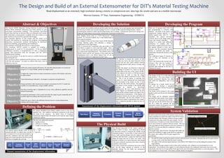
Abstract & Objectives
Read displacement at an extremely high resolution during a tensile or compression test, data logs the results and acts as a mobile microscope
Present transmission of the displacement information
Objective 1 Define the systems present deficiencies, the operation and procedure of a tensile test
using D.I.T’s Lloyd LR30K, and the test samples used.
Objective 2 Compare the contact and non-contact extensometer systems on the market, and assess
an ideal solution
Objective 3 Upon determining an alternative, investigate its properties and applications.
Objective 4 Design and build a fully functional non-contact extensometer for D.I.T’s tensile test
machine at a reasonable price, using available software.
Objective 5 Develop an interface that is comprehensive to use, with a calibration capability and user
defined functionality.
Objective 6 Evaluate the performance of the system and refine the output to gain comparable and if
possible improved readings than the present system.
Objective 7 Enable the user to observe the difference between the new systems displacement
readings and Nexygen output.
Test
Piece
Holding
Apparatus
Cross
bar
Twin
Drive
Screws
Servo
Motor
Drive
Belt
Encoder
Disc
Nexygen
Software
Defining the Problem
The project benefitted from having regular access to the D.I.T
Materials Lab. This enabled a continuous assessment of the needs
and wants of the customer. An initial ‘Voice of Customer’
questionnaire helped define the problem and continual input helped
to define the solution.
The internal optical decoder works on the
standard principle of a digital rotary encoder.
It is mounted in its own unit and rotated by a
belt drive attached to the main shaft of the
large servo motor that drives the twin screws
that lower or heighten the cross bar.
The Lloyds LR30K Materials Testing Machine located in DIT
Bolton Street materials laboratory has been proven to give
inaccurate extensometer readings. This generates inaccurate
strain data that has an adverse effect on materials tests results.
The alternative extensometers available from the vendor or on
the market are beyond the materials labs budget.
The principle objective of this project and the report is to
resolve this problem by analysing the problem, investigating
alternative extensometer systems, developing an alternative
and then building, programming and installing it.
This solution would take the form of a vision system.
The resulting ‘MTVS’ system is capable of reading a
displacement as small as 1.8 micrometres. It has an inbuilt
calibration function, a comprehensive UI and a comparison
graph that represents both the Nexygen and the MTVS
displacement readings.
As an extra feature, it can also be used as a mobile microscopic
measuring device.
The system has been validated and the primary user is satisfied
with the end product. In order to achieve this end, a list of
objectives was set:
The imaging device used is a TE70 Microscopic USB
camera. It is the best available way to read displacement to
the required resolution.
It is clamped to the cross bar of the Lloyds LR30k Materials
Testing Machine gantry and translates a change in
displacement of the target image.
This is converted into a numerical value and written to file
and drawn to graph as a stress and strain graph. There is
also a mobile microscope interface function that can be used
as a microscopic measuring device. The software used is NI
IMAQ Vision and the core function of the system for the
displacement tests is the IMAQ Optical Flow VI, set to
track the movement of a single pixel on the Y axis.
The decision to mount the camera on the
crossbar was vital to the entire direction of the
project, and the only viable solution without
purchasing purpose built cameras, housing and
lenses.
Initially the project was directed at observing
the change in position of a mark on the test
subject held in the jaws of the Lloyds LR30K.
If the camera to be used is a USB Microscopic
camera then in order to keep the image
onscreen, the camera would have to move with
it. This is not an option, so directing the
camera at a static background and measuring
the movement of the camera on the Y axis
became the only viable solution. By mounting
the camera on the crossbar of the LR30K and
reading an upward or downward
displacement, the user could determine with
fewer degrees of separation between the test
piece and the software output (see Firgure.18) a
displacement in micrometres. If the degrees of
separation between the test piece and software
are diminished, and the extra element of no
mechanical contact is introduced to the system,
then it should be possible to reduce an error in
reading.
The research into available solutions and the results from the customer survey and ongoing input indicated that
the best way to attain more accurate readings for D.I.T’s Lloyds LR30K materials testing machine, without
purchasing the expensive vendor specific plug and play unit, or another extensometer system was to design and
build a PC based optical vision system extensometer to determine displacement.
Transmission of the displacement information with MTVS System
Test Piece
Holding
Apparatus
Crossbar
Camera
Clamp
Camera
MTVS
Software
The Physical Build
The physical placement of the camera required a
clamp to hold it in place. This clamp had to absorb
the maximum amount of vibration the LR30K would
commonly produce. As the field of vision would only
cover 1mm², and the distance from the subject image
would be 3mm maximum, a slight jolt could knock the
image off target and out of focus very easily. The
moment of fracture of a typical dog bone steel sample
is the most commonly occurring event where vibration
would be a real concern.
Tests where carried out to determine the extent of this
jolt, but the image retained its position, so the
materials chosen for the build are inexpensive
overcompensation.
With over 24 purpose built SUB VI’s
the programming is extensive and
detailed. The heart of the tensile and
compression testing function is the
IMAQ Optical Flow LKP VI. This
calculates the optical movement
(velocity flow) in the image using the
Lucas and Kanede algorithm. The
method is a widely used differential
calculation to estimate that the
movement is equal in the pixels close to
the particle selected to track, and it
assumes that the movement between
frames is consistent and steady. It
statistically estimates the location of the
particle.
The Calibration Gauge VI function is
one of many sub structures in the
program .
This is the function that overlays the 5
reference lines that are overlaid in
proportion to the 100 micrometre
graticule slide markings by the user to
calibrate the system.
Building the UI
The design of the UI is both functional
and intuitive. The extra feature of the
mobile microscope function was added
and fulfils the adaptability brief of the
project.
To operate for a simple tensile test the
user will run through a designated
sequence in tandem with the Nexygen test
set-up procedure.
The results will be defined in the output
graphs on the next tab and user designated
text files.
The image can be calibrated remotely
provided the same model of the camera is
used as the one mounted on the LR30K
The user can run the MTVS from any of
the PC’s within the materials lab and
potentially transfer the program to any PC
with the required LabVIEW software.
The particle
starts here
Change in displacement
The image
moves in an
upward
direction
Nexygen Load vs Displacement
Nexygen Load vs Displacement
System Validation
In order to prove the success of the project a series of tests
where undertaken to match the output of the MTVS system
with the output of the Nexygen system by doing 6 simple
compression test using exactly the same settings. The test
selected was a ‘Compress to Limit General Purpose Test’,
set to move 0.5mm at a speed of 3mm per second. This very
slow and slight movement helped to prove the resolution of
the MTVS system and offered a comparative reference
between systems.
The graph image, taken from the ‘Document and Graph’ tab
shows the variability in signal of the MTVS as opposed to
the steady state reading of the Nexygen suggests two
possibilities:
1. The MTVS system is giving far greater accuracy and precision in its reading, indicating that the Nexygen software
is acting solely on the basis that the motor is turning.
2. The nature of the statistical approximations of the IMAQ LKP Optical Flow are fluctuating the position of the
target particle.
But if the linear Nexygen output is correct, then at this resolution, why vibration is not accounted for or even
represented. The similarity in the signals is a clear indication that they are reading the same result, but in two areas
specifically (the first rise of load and the final signal at the end of the displacement) there is a clear discrepancy. This
was repeated in 5 of the 6 tests. This clearly warrants further investigation.