Downloaded 18 times


![P1730 A/T INTERLOCK ................................. 233
.
TCM ................................................................. 256
.
Description ............................................................233
.
DTC Logic .............................................................233
.
Judgment of A/T Interlock .....................................233
.
Diagnosis Procedure ............................................234
.
Reference Value .................................................. 256
.
Wiring Diagram - A/T CONTROL SYSTEM - ....... 263
.
Fail-Safe ............................................................... 266
.
Protection Control ................................................ 269
.
DTC Inspection Priority Chart .............................. 270
.
DTC Index ............................................................ 270
.
P1734 A/T 7TH GEAR FUNCTION ................ 235
.
Description ............................................................235
.
DTC Logic .............................................................235
.
Diagnosis Procedure ............................................236
.
SYMPTOM DIAGNOSIS ........................... 272
P1815 MANUAL MODE SWITCH .................. 237
.
Symptom Table .................................................... 272
.
Description ............................................................237
.
DTC Logic .............................................................237
.
Diagnosis Procedure ............................................237
.
Component Inspection (Manual Mode Switch) .....241
.
Component Inspection [Paddle Shifter (Shift-up)]..241
Component Inspection [Paddle Shifter (Shiftdown)] ...................................................................241
.
P2713 HIGH AND LOW REVERSE CLUTCH
SOLENOID VALVE ......................................... 243
.
Description ............................................................243
.
DTC Logic .............................................................243
.
Diagnosis Procedure ............................................243
.
P2722 LOW BRAKE SOLENOID VALVE ...... 244
.
Description ............................................................244
.
DTC Logic .............................................................244
.
Diagnosis Procedure ............................................244
.
P2731 2346 BRAKE SOLENOID VALVE ...... 245
.
SYSTEM SYMPTOM ....................................... 272
.
PRECAUTION ........................................... 277
PRECAUTIONS ............................................... 277
.
Precaution for Supplemental Restraint System
(SRS) "AIR BAG" and "SEAT BELT PRE-TENSIONER" .............................................................. 277
.
General Precautions ............................................ 277
.
Service Notice or Precaution ............................... 278
.
PREPARATION ......................................... 279
PREPARATION ............................................... 279
.
Commercial Service Tool ..................................... 279
.
ON-VEHICLE MAINTENANCE ................. 280
A/T FLUID ........................................................ 280
.
Changing .............................................................. 280
.
Adjustment ........................................................... 281
.
Description ............................................................245
.
DTC Logic .............................................................245
.
Diagnosis Procedure ............................................245
.
A/T FLUID COOLER ....................................... 282
.
P2807 DIRECT CLUTCH SOLENOID VALVE. 246
STALL TEST ................................................... 285
.
Description ............................................................246
.
DTC Logic .............................................................246
.
Diagnosis Procedure ............................................246
.
Cleaning ............................................................... 282
.
Inspection ............................................................. 284
.
Inspection and Judgment ..................................... 285
.
A/T POSITION ................................................. 286
.
Inspection and Adjustment ................................... 286
.
MAIN POWER SUPPLY AND GROUND CIRCUIT ................................................................ 247
.
ON-VEHICLE REPAIR .............................. 287
Description ............................................................247
.
Diagnosis Procedure ............................................247
.
CONTROL DEVICE ......................................... 287
.
SHIFT POSITION INDICATOR CIRCUIT ....... 249
.
Description ............................................................249
.
Component Function Check .................................249
.
Diagnosis Procedure ............................................249
.
SHIFT LOCK SYSTEM ................................... 250
.
Exploded View ..................................................... 287
.
Removal and Installation ...................................... 288
.
Disassembly and Assembly ................................. 288
.
Inspection and Adjustment ................................... 289
.
CONTROL ROD .............................................. 290
.
Exploded View ..................................................... 290
.
Removal and Installation ...................................... 290
.
Inspection and Adjustment ................................... 290
.
Description ............................................................250
.
Wiring Diagram - A/T SHIFT LOCK SYSTEM - ....250
.
Component Function Check .................................251
.
Diagnosis Procedure ............................................252
.
Component Inspection (Shift Lock Unit) ...............254
.
Component Inspection (Stop Lamp Switch) .........254
.
PADDLE SHIFTER .......................................... 291
.
ECU DIAGNOSIS ...................................... 256
.
OIL PAN ........................................................... 292
.
Revision: 2008 October
Exploded View ..................................................... 291
.
Removal and Installation ...................................... 291
.
Exploded View ..................................................... 292
.
TM-4
2009 370Z](https://image.slidesharecdn.com/tm-140302061414-phpapp01/85/Tm-4-320.jpg)

![M/T SYSTEM
[6MT: FS6R31A]
< FUNCTION DIAGNOSIS >
FUNCTION DIAGNOSIS
M/T SYSTEM
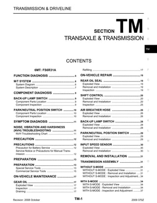
System Diagram
INFOID:0000000004684743
CROSS-SECTIONAL VIEW
Without S-MODE
JPDIC0027ZZ
1.
Front cover
2.
Main drive gear
3.
Counter shaft
4.
6th counter gear
5.
2nd counter gear
6.
1st counter gear
7.
3rd counter gear
8.
3rd-4th synchronizer hub
9.
3rd-4th coupling sleeve
10. 4th counter gear
11. Adapter plate
12. Reverse idler gear
13. Reverse idler shaft
14. Reverse counter gear
15. Mainshaft
16. Rear extension
17. Striking rod
18. Reverse synchronizer hub
19. Reverse coupling sleeve
20. Reverse main gear
21. 4th main gear
22. 3rd main gear
23. 1st main gear
24. 1st-2nd coupling sleeve
25. 1st-2nd synchronizer hub
26. 2nd main gear
27. 6th main gear
28. Transmission case
29. 5th-6th coupling sleeve
30. 5th-6th synchronizer hub
Revision: 2008 October
TM-6
2009 370Z](https://image.slidesharecdn.com/tm-140302061414-phpapp01/85/Tm-6-320.jpg)
![M/T SYSTEM
[6MT: FS6R31A]
< FUNCTION DIAGNOSIS >
With S-MODE
A
B
C
TM
E
F
G
H
I
JPDIC0521ZZ
1.
Front cover
2.
Main drive gear
3.
Counter shaft
4.
6th counter gear
5.
2nd counter gear
6.
1st counter gear
7.
3rd counter gear
8.
3rd-4th synchronizer hub
9.
3rd-4th coupling sleeve
J
10. 4th counter gear
11. Adapter plate
12. Reverse idler gear
13. Reverse idler shaft
14. Reverse counter gear
15. Mainshaft
16. Rear extension
17. Striking rod
18. Reverse synchronizer hub
19. Reverse coupling sleeve
20. Gear lever position sensor
21. Gear lever position sensor magnet
22. Reverse main gear
23. 4th main gear
24. 3rd main gear
25. 1st main gear
26. 1st-2nd coupling sleeve
27. 1st-2nd synchronizer hub
28. 2nd main gear
29. 6th main gear
30. Transmission case
31. 5th-6th coupling sleeve
32. 5th-6th synchronizer hub
System Description
K
L
M
INFOID:0000000004684744
N
DOUBLE-CONE SYNCHRONIZER
The 4th gear is equipped with a double-cone synchronizer to reduce the operating force of the control lever.
O
TRIPLE-CONE SYNCHRONIZER
P
Revision: 2008 October
TM-7
2009 370Z](https://image.slidesharecdn.com/tm-140302061414-phpapp01/85/Tm-7-320.jpg)
![M/T SYSTEM
< FUNCTION DIAGNOSIS >
The 1st, 2nd, and 3rd gears are equipped with a triple-cone synchronizer to reduce the operating force of the control lever.
[6MT: FS6R31A]
PCIB1432E
REVERSE GEAR NOISE PREVENTION FUNCTION
Reverse gear noise prevention makes smooth operation possible and restrains the gear's grating noise by
stopping the rotation of each gear when gear is shifted to reverse position.
Revision: 2008 October
TM-8
2009 370Z](https://image.slidesharecdn.com/tm-140302061414-phpapp01/85/Tm-8-320.jpg)
![BACK-UP LAMP SWITCH
[6MT: FS6R31A]
< COMPONENT DIAGNOSIS >
COMPONENT DIAGNOSIS
A
BACK-UP LAMP SWITCH
Component Parts Location
1
INFOID:0000000004684745
B
C
: Back-up lamp switch
TM
E
JPDIC0588ZZ
Component Inspection
INFOID:0000000004684746
F
1.CHECK BACK-UP LAMP SWITCH
1.
2.
G
Disconnect back-up lamp switch connector. Refer to TM-28, "Removal and Installation".
Check continuity between back-up lamp switch terminals.
Terminal
1
2
Condition
H
Continuity
Reverse gear position
Existed
Except reverse gear position
Not existed
I
Is the inspection result normal?
YES >> INSPECTION END
NO
>> Replace back-up lamp switch. Refer to TM-28, "Removal and Installation".
J
K
L
M
N
O
P
Revision: 2008 October
TM-9
2009 370Z](https://image.slidesharecdn.com/tm-140302061414-phpapp01/85/Tm-9-320.jpg)
![PARK/NEUTRAL POSITION SWITCH
[6MT: FS6R31A]
< COMPONENT DIAGNOSIS >
PARK/NEUTRAL POSITION SWITCH
Component Parts Location
1
INFOID:0000000004684747
: Park/Neutral position (PNP) switch
JPDIC0589ZZ
Component Inspection
INFOID:0000000004684748
1.CHECK PARK/NEUTRAL POSITION (PNP) SWITCH
1.
2.
Disconnect park/neutral position (PNP) switch connector. Refer to TM-29, "Removal and Installation".
Check continuity between park/neutral position (PNP) switch terminals.
Terminal
1
2
Condition
Continuity
Neutral position
Existed
Except neutral position
Not existed
Is the inspection result normal?
YES >> INSPECTION END
NO
>> Replace park/neutral position (PNP) switch. Refer to TM-29, "Removal and Installation".
Revision: 2008 October
TM-10
2009 370Z](https://image.slidesharecdn.com/tm-140302061414-phpapp01/85/Tm-10-320.jpg)
![NOISE, VIBRATION AND HARSHNESS (NVH) TROUBLESHOOTING
[6MT: FS6R31A]
< SYMPTOM DIAGNOSIS >
SYMPTOM DIAGNOSIS
A
NOISE, VIBRATION AND HARSHNESS (NVH) TROUBLESHOOTING
NVH Troubleshooting Chart
INFOID:0000000004684749
Symptoms
1
1
Hard to shift or will not shift
1
1
Jumps out of gear
2
INSERT SPRING (Damaged)
BAULK RING (Worn or damaged)
BEARING (Worn or damaged)
GEAR (Worn or damaged)
H
I
J
K
L
M
N
O
3
P
2
2
1
TM-11
G
TM-43 (Without S-MODE) or TM-75 (With S-MODE)
SHIFT FORK (Worn)
CHECK PLUG RETURN SPRING AND CHECK BALL (Worn or damaged)
F
3
3
Revision: 2008 October
E
2
Oil leakage
C
TM
TM-20
TM-17
Reference
Noise
OIL SEAL (Worn or damaged)
TM-43 (Without S-MODE) or TM-75 (With S-MODE)
GASKET (Damaged)
OIL (Oil level is high)
OIL (Wrong oil)
OIL (Oil level is low)
SUSPECTED PARTS
(Possible cause)
SHIFT CONTROL LINKAGE (Worn)
Use the chart below to find the cause of the symptom. The numbers indicate the order of the inspection. If necessary, repair or replace these parts.
B
2
1
2
2
2
2009 370Z](https://image.slidesharecdn.com/tm-140302061414-phpapp01/85/Tm-11-320.jpg)
![PRECAUTIONS
[6MT: FS6R31A]
< PRECAUTION >
PRECAUTION
PRECAUTIONS
Precaution for Battery Service
INFOID:0000000004778863
Before disconnecting the battery, lower both the driver and passenger windows. This will prevent any interference between the window edge and the vehicle when the door is opened/closed. During normal operation, the
window slightly raises and lowers automatically to prevent any window to vehicle interference. The automatic
window function will not work with the battery disconnected.
Service Notice or Precautions for Manual Transmission
INFOID:0000000004684750
CAUTION:
• Never reuse CSC (Concentric Slave Cylinder) body and CSC tube. Because CSC slides back to the
original position every time when removing transmission assembly. At this timing, dust on the sliding parts may damage a seal of CSC and may cause clutch fluid leakage. Refer to CL-16, "Removal
and Installation".
• Never reuse drained gear oil.
• Check the oil level or replace oil with vehicle on level ground.
• During removal or installation, keep inside of transmission clear of dust or dirt.
• Check for the correct installation status prior to removal or disassembly. If matching marks are
required, be certain they never interfere with the function of the parts they are applied.
• In principle, tighten bolts or nuts gradually in several steps working diagonally from inside to outside. If tightening sequence is specified, observe it.
• Never damage sliding surfaces and mating surfaces.
• Never hold control lever housing to prevent the bushing of control lever housing from deformation
when moving transmission assembly.
• Never touch lip of oil seal.
Revision: 2008 October
TM-12
2009 370Z](https://image.slidesharecdn.com/tm-140302061414-phpapp01/85/Tm-12-320.jpg)
![PREPARATION
[6MT: FS6R31A]
< PREPARATION >
PREPARATION
A
PREPARATION
Special Service Tools
INFOID:0000000004684751
B
The actual shapes of Kent-Moore tools may differ from those of special service tools illustrated here.
Tool number
(Kent-Moore No.)
Tool name
C
Description
Removing rear oil seal
KV381054S0
(J-34286)
Puller
TM
E
ZZA0601D
F
Installing rear oil seal
ST33400001
(J-26082)
Drift
a: 60 mm (2.36 in) dia.
b: 47 mm (1.85 in) dia.
G
H
ZZA0814D
Holding an adapter plate
ST22490000
(-)
Adapter setting plate
a: 156 mm (6.14 in)
b: 220 mm (8.66 in)
I
J
S-NT407
Installing counter rear bearing
ST33200000
(J-26082)
Drift
a: 60 mm (2.36 in) dia.
b: 44.5 mm (1.752 in) dia.
K
L
ZZA1002D
M
Installing reverse synchronizer hub assembly
KV32103300
(J-46529)
Press plate
a: 73 mm (2.87 in)
N
O
PCIB0165J
Installing reverse synchronizer hub assembly
ST01530000
(-)
Drift
a: 50 mm (1.97 in) dia.
b: 41 mm (1.61 in) dia.
P
ZZA0534D
Revision: 2008 October
TM-13
2009 370Z](https://image.slidesharecdn.com/tm-140302061414-phpapp01/85/Tm-13-320.jpg)
![PREPARATION
[6MT: FS6R31A]
< PREPARATION >
Tool number
(Kent-Moore No.)
Tool name
Description
Installing reverse counter gear
ST23860000
(-)
Drift
a: 38 mm (1.50 in) dia.
b: 33 mm (1.30 in) dia.
ZZA0534D
Installing front oil seal
KV38102100
(J-25803-01)
Drift
a: 44 mm (1.73 in) dia.
b: 36 mm (1.42 in) dia.
c: 24.5 mm (0.965 in) dia.
ZZA1046D
Installing striking rod oil seal
ST33061000
(J-8107-2)
Drift
a: 28.5 mm (1.122 in) dia.
b: 38 mm (1.50 in) dia.
ZZA1023D
Installing main drive gear bearing
KV32102700
(-)
Drift
a: 48.6 mm (1.913 in) dia.
b: 41.6 mm (1.638 in) dia.
ZZA0534D
• Installing 5th-6th synchronizer hub assembly
• Installing mainshaft bearing
• Installing reverse main gear bushing
• Installing 3rd gear bushing
• Installing 3rd-4th synchronizer hub assembly
ST30911000
(-)
Inserter
a: 98 mm (3.86 in) dia.
b: 40.5 mm (1.594 in) dia.
ZZA0920D
• Installing 1st-2nd synchronizer hub assembly
• Installing 1st gear bushing
ST27861000
(-)
Support ring
a: 62 mm (2.44 in) dia.
b: 52 mm (2.05 in) dia.
ZZA0832D
• Installing 3rd main gear
• Installing 4th main gear
ST30022000
(-)
Inserter
a: 110 mm (4.33 in) dia.
b: 46 mm (1.81 in) dia.
ZZA0920D
Revision: 2008 October
TM-14
2009 370Z](https://image.slidesharecdn.com/tm-140302061414-phpapp01/85/Tm-14-320.jpg)
![PREPARATION
[6MT: FS6R31A]
< PREPARATION >
Tool number
(Kent-Moore No.)
Tool name
A
Description
Installing 4th counter gear thrust washer
KV40100630
(J-26092)
Inserter
a: 67.5 mm (2.657 in) dia.
b: 38.5 mm (1.516 in) dia.
B
C
ZZA0920D
Installing counter rear bearing inner race
ST30032000
(J-26010-01)
Inserter
a: 80 mm (3.15 in) dia.
b: 31 mm (1.22 in) dia.
TM
E
F
ZZA0920D
Measuring wear of inner baulk ring
ST30031000
(J-22912-01)
Puller
G
H
ZZA0537D
Commercial Service Tools
INFOID:0000000004684752
Tool name
Description
Puller
• Removing reverse main gear
• Removing reverse synchronizer hub
• Removing reverse counter gear
I
J
K
L
NT077
Puller
Removing each bearing, gear, and bushing
M
N
ZZB0823D
O
P
Revision: 2008 October
TM-15
2009 370Z](https://image.slidesharecdn.com/tm-140302061414-phpapp01/85/Tm-15-320.jpg)
![PREPARATION
[6MT: FS6R31A]
< PREPARATION >
Tool name
Description
Pin punch
a: 6 mm (0.24 in) dia.
Removing and installing each retaining pin
NT410
Power tool
Loosening bolts and nuts
PBIC0190E
Revision: 2008 October
TM-16
2009 370Z](https://image.slidesharecdn.com/tm-140302061414-phpapp01/85/Tm-16-320.jpg)
![GEAR OIL
[6MT: FS6R31A]
< ON-VEHICLE MAINTENANCE >
ON-VEHICLE MAINTENANCE
A
GEAR OIL
Exploded View
INFOID:0000000004684838
Refer to TM-43, "WITHOUT S-MODE : Exploded View" (Without S-MODE) or TM-75, "WITH S-MODE :
Exploded View" (With S-MODE).
Inspection
B
C
INFOID:0000000004684756
OIL LEAKAGE
TM
Make sure that gear oil is not leaking from transmission or around it.
OIL LEVEL
1.
2.
3.
4.
Remove filler plug (1) and gasket from transmission case.
Check the oil level from filler plug mounting hole as shown in the
figure.
CAUTION:
Never start engine while checking oil level.
Set a gasket on filler plug and then install it to transmission
case.
CAUTION:
Never reuse gasket.
Tighten filler plug to the specified torque. Refer to TM-43,
"WITHOUT S-MODE : Exploded View" (Without S-MODE) or
TM-75, "WITH S-MODE : Exploded View" (With S-MODE).
Draining
1.
2.
3.
4.
5.
G
H
JPDIC0590ZZ
Start the engine and let it run to warm up transmission.
Stop the engine.
Remove drain plug and gasket from transmission case and then drain gear oil.
Set a gasket on drain plug and install it to transmission case.
CAUTION:
Never reuse gasket.
Tighten drain plug to the specified torque. Refer to TM-43, "WITHOUT S-MODE : Exploded View" (Without S-MODE) or TM-75, "WITH S-MODE : Exploded View" (With S-MODE).
Oil capacity
J
K
L
M
: Refer to MA-14, "FOR NORTH AMERICA
: Fluids and Lubricants" (For North
America) or MA-15, "EXCEPT FOR
NORTH AMERICA : Fluids and Lubricants" (Except for North America).
: Refer to TM-135, "General Specification".
N
O
JPDIC0590ZZ
CAUTION:
Never reuse drained gear oil.
After refilling gear oil, check the oil level. Refer to TM-17, "Inspection".
Set a gasket on filler plug and then install it to transmission case.
CAUTION:
Never reuse gasket.
Revision: 2008 October
I
INFOID:0000000004684755
Remove filler plug (1) and gasket from transmission case.
Fill with new gear oil to transmission as shown in the figure.
Oil grade and
viscosity
3.
4.
F
INFOID:0000000004684754
Refilling
1.
2.
E
TM-17
2009 370Z
P](https://image.slidesharecdn.com/tm-140302061414-phpapp01/85/Tm-17-320.jpg)
![GEAR OIL
[6MT: FS6R31A]
< ON-VEHICLE MAINTENANCE >
5. Tighten filler plug to the specified torque. Refer to TM-43, "WITHOUT S-MODE : Exploded View" (Without
S-MODE) or TM-75, "WITH S-MODE : Exploded View" (With S-MODE).
Revision: 2008 October
TM-18
2009 370Z](https://image.slidesharecdn.com/tm-140302061414-phpapp01/85/Tm-18-320.jpg)
![REAR OIL SEAL
[6MT: FS6R31A]
< ON-VEHICLE REPAIR >
ON-VEHICLE REPAIR
A
REAR OIL SEAL
Exploded View
INFOID:0000000004684839
Refer to TM-43, "WITHOUT S-MODE : Exploded View" (Without S-MODE) or TM-75, "WITH S-MODE :
Exploded View" (With S-MODE).
Removal and Installation
C
INFOID:0000000004684758
REMOVAL
1.
2.
B
TM
Separate propeller shaft assembly. Refer to DLN-7, "Removal and Installation".
Remove rear oil seal from rear extension using the puller [SST:
KV381054S0 (J-34286)].
CAUTION:
Never damage rear extension.
E
F
G
PCIB0194E
H
INSTALLATION
1.
Install rear oil seal (1) to rear extension using the drift [SST:
ST33400001 (J-26082)].
Dimension “H”
2.
I
: 1.2 – 2.2 mm (0.047 – 0.087 in)
CAUTION:
Never incline rear oil seal.
Install propeller shaft assembly. Refer to DLN-7, "Removal and
Installation".
J
K
JPDIC0587ZZ
Inspection
INFOID:0000000004684759
L
INSPECTION AFTER INSTALLATION
M
Check the oil level. Refer to TM-17, "Inspection".
N
O
P
Revision: 2008 October
TM-19
2009 370Z](https://image.slidesharecdn.com/tm-140302061414-phpapp01/85/Tm-19-320.jpg)
![SHIFT CONTROL
[6MT: FS6R31A]
< ON-VEHICLE REPAIR >
SHIFT CONTROL
Exploded View
INFOID:0000000004684760
JPDIC0495GB
1.
Shift knob
2.
Insulator
3.
4.
Console finisher assembly
5.
Hole cover
6.
Control lever boot B
7.
Hole insulator
8.
Control lever boot A
9.
Guide plate
10. Control lever
11. Control lever spring
13. Control rod
Seat
14. Control rod boot
12. Control lever housing
: Apply multi-purpose grease.
: Apply Genuine Medium Strength Thread Locking Sealant or an equivalent. Refer to GI-17, "Recommended Chemical Products and Sealants".
Refer to GI-4, "Components" for symbols not described on the above.
Removal and Installation
INFOID:0000000004684761
REMOVAL
1.
a.
Remove shift knob with the following procedure.
Release metal clips on console finisher assembly. Refer to IP-23, "Removal and Installation".
Revision: 2008 October
TM-20
2009 370Z](https://image.slidesharecdn.com/tm-140302061414-phpapp01/85/Tm-20-320.jpg)
![SHIFT CONTROL
< ON-VEHICLE REPAIR >
b. Lift console finisher assembly and then set suitable pliers to control lever.
CAUTION:
Put waste cloth (A) between a suitable pliers and control
lever to avoid damaging control lever.
[6MT: FS6R31A]
A
B
C
JPDIC0611ZZ
TM
c.
d.
e.
f.
2.
3.
4.
5.
Set suitable pliers to shift knob.
CAUTION:
Put waste cloth (A) between a suitable pliers and shift knob
to avoid damaging shift knob.
Keeping control lever in place with a suitable pliers, loosen shift
knob with a suitable pliers.
NOTE:
Remove shift knob from control lever keeping a suitable pliers in
place because a certain power to turn shift knob is still necessary even after adhesive is peeled.
Remove shift knob from control lever.
Remove insulator from shift knob.
Remove seat from control lever.
CAUTION:
Never lose seat.
Remove console finisher assembly.
Release control rod boot from control lever housing.
Remove mounting bolt (
control rod.
E
F
G
JPDIC0612ZZ
H
I
) and then separate control lever and
J
K
L
SCIA2561J
M
6.
Remove clips (
) from hole cover.
N
O
P
JPDIC0614ZZ
Revision: 2008 October
TM-21
2009 370Z](https://image.slidesharecdn.com/tm-140302061414-phpapp01/85/Tm-21-320.jpg)
![SHIFT CONTROL
[6MT: FS6R31A]
< ON-VEHICLE REPAIR >
7.
8.
Remove mounting bolts ( ) and then remove hole cover.
CAUTION:
Never damage center console assembly.
Remove control lever boot B, hole insulator, and control lever
boot A.
JPDIC0613ZZ
9. Remove mounting bolts ( ) while holding guide plate.
10. Remove guide plate, control lever, and control lever spring from
control lever housing.
JPDIC0615ZZ
INSTALLATION
1.
2.
3.
4.
5.
Apply multi-purpose grease to sliding surface of control lever.
Install control lever spring, control lever, and guide plate to control lever housing.
Temporarily tighten guide plate mounting bolts while holding guide plate.
Install control lever to control rod and then tighten mounting bolt
( ) to the specified torque.
Install control rod boot to control lever housing.
CAUTION:
Fit control rod boot to the groove on control lever housing.
SCIA2561J
6.
Install guide plate with the following procedure.
Revision: 2008 October
TM-22
2009 370Z](https://image.slidesharecdn.com/tm-140302061414-phpapp01/85/Tm-22-320.jpg)
![SHIFT CONTROL
< ON-VEHICLE REPAIR >
a. Shift the control lever to 6th gear position (A).
b. Lightly shift control lever to the reverse gear direction until it
stops, and keep control lever in this position.
c. Set guide plate so that guide plate portion (B) contacts control
lever portion (C).
d. Temporarily tighten mounting bolt (D).
[6MT: FS6R31A]
A
B
C
TM
E
F
G
JPDIC0625ZZ
e.
f.
g.
h.
i.
Shift the control lever to 5th gear position (A).
Lightly shift control lever to the reverse gear direction until it
stops, and keep control lever in this position.
Set guide plate so that guide plate portion (B) contacts control
lever portion (C).
Tighten mounting bolt (D) to the specified torque.
Tighten mounting bolts (E) and (F) to the specified torque.
H
I
J
K
L
M
N
JPDIC0626ZZ
7.
8.
Install control lever boot A (1) to control lever (2).
CAUTION:
• Check that groove of control lever boot A is engaged to
guide plate (3).
• Be careful that control lever boot A is installed according
to the specified location ( ).
Install hole insulator and control lever boot B.
CAUTION:
Be careful with the orientation of hole insulator and control
lever boot B.
O
P
JPDIC0624ZZ
Revision: 2008 October
TM-23
2009 370Z](https://image.slidesharecdn.com/tm-140302061414-phpapp01/85/Tm-23-320.jpg)
![SHIFT CONTROL
[6MT: FS6R31A]
< ON-VEHICLE REPAIR >
9.
Install hole cover and then tighten mounting bolts (
specified torque.
CAUTION:
• Never damage center console assembly.
• Be careful with the orientation of hole cover.
) to the
JPDIC0613ZZ
10. Install clips ( ) to hole cover.
11. Install console finisher assembly. Refer to IP-23, "Removal and
Installation".
JPDIC0614ZZ
12. Install seat (1) and insulator (2) to control lever (3).
CAUTION:
• Be careful with the orientation of seat.
• Never lose seat.
13. Apply thread locking sealant to control lever threads and then
install shift knob to control lever.
• Use Genuine Medium Strength Thread Locking Sealant or
an equivalent. Refer to GI-17, "Recommended Chemical
Products and Sealants".
CAUTION:
Remove the remaining adhesive on control lever and shift
knob threads.
14. Set shift knob in the correct position with the following procedure.
Revision: 2008 October
TM-24
JPDIC0627ZZ
2009 370Z](https://image.slidesharecdn.com/tm-140302061414-phpapp01/85/Tm-24-320.jpg)
![SHIFT CONTROL
< ON-VEHICLE REPAIR >
a. When tightening shift knob, if shift knob comes to the proper
position within 1/2 turn from the position at which resistance
begins to be felt, tighten it 1 more turn to set it in the proper position.
[6MT: FS6R31A]
A
B
: Vehicle front
A
b.
: Proper position
B
: Start position on reaction force
C
If it takes more than 1/2 turn from the position at which resistance begins to be felt, tighten it to set it in the proper position.
CAUTION:
• Never adjust shift knob with loosing.
• After adjusting to the proper position, until 30 minutes
pass, never operate the shift knob intensely such as
screwing or turning shift knob to opposite direction since
a locking sealant becomes stiff.
TM
E
F
G
JPDIC0525ZZ
Inspection
INFOID:0000000004684762
H
INSPECTION AFTER INSTALLATION
Control Lever
• When control lever is shifted to each gear position, check that there is no interference or boot disengagement.
• When control lever is shifted to each gear position, check that there is no binding, noise, or backlash that
disturbs shifting.
• When control lever is shifted to the 5th or 6th gear position by being pressed in the right side direction without being pressed downward, check that there is no binding or poor gear engagement.
• When control lever is shifted to the 1st-2nd side and released, check that control lever returns smoothly to
the neutral position.
• When control lever is shifted to the 5th-6th side and released, check that control lever returns smoothly to
the neutral position.
• When control lever is in a position other than the reverse gear position, check that control lever can be
pressed downward.
• When control lever is pressed and held downward, check that control lever can be shifted to the reverse
gear position.
• When control lever is shifted from the reverse gear position to the neutral position, check that control lever
returns smoothly to the neutral position with spring power.
• When control lever is not pressed downward, check that control lever cannot be shifted to the reverse gear
position.
Shift Knob
Check that there is no shift knob dislocation.
I
J
K
L
M
N
O
Boot
Check that there is no damage, twist, or dislocation of boot.
P
Revision: 2008 October
TM-25
2009 370Z](https://image.slidesharecdn.com/tm-140302061414-phpapp01/85/Tm-25-320.jpg)
![AIR BREATHER HOSE
[6MT: FS6R31A]
< ON-VEHICLE REPAIR >
AIR BREATHER HOSE
Exploded View
INFOID:0000000004684763
JPDIC0638ZZ
1.
Air breather tube
2.
Breather tube
3.
Air breather hose
: Refer to “INSTALLATION” in TM-31, "WITHOUT S-MODE : Removal and Installation" (Without S-MODE) or TM-34, "WITH SMODE : Removal and Installation" (With S-MODE) for the tightening torque.
Removal and Installation
INFOID:0000000004684764
REMOVAL
Refer to TM-26, "Exploded View" for removal procedure.
INSTALLATION
Note the following, and refer to TM-26, "Exploded View" for installation procedure.
CAUTION:
• Make sure there are no pinched or restricted areas on the air breather hose caused by bending or
winding when installing it.
• Be sure to insert air breather hose into breather tube until
hose end reaches the tube's base.
SCIA2663J
Revision: 2008 October
TM-26
2009 370Z](https://image.slidesharecdn.com/tm-140302061414-phpapp01/85/Tm-26-320.jpg)
![AIR BREATHER HOSE
< ON-VEHICLE REPAIR >
• Be sure to insert air breather hose into air breather tube until
hose end reaches the radius curve end.
[6MT: FS6R31A]
A
B
C
JPDIC0469ZZ
TM
E
F
G
H
I
J
K
L
M
N
O
P
Revision: 2008 October
TM-27
2009 370Z](https://image.slidesharecdn.com/tm-140302061414-phpapp01/85/Tm-27-320.jpg)
![BACK-UP LAMP SWITCH
[6MT: FS6R31A]
< ON-VEHICLE REPAIR >
BACK-UP LAMP SWITCH
Exploded View
INFOID:0000000004684842
Refer to TM-43, "WITHOUT S-MODE : Exploded View" (Without S-MODE) or TM-75, "WITH S-MODE :
Exploded View" (With S-MODE).
Removal and Installation
INFOID:0000000004684766
REMOVAL
1.
2.
Disconnect the battery cable from the negative terminal.
Disconnect clip (A) from bracket (1).
: Vehicle front
3.
4.
Remove bracket from rear extension.
Disconnect back-up lamp switch connector.
JPDIC0522ZZ
5.
Remove back-up lamp switch from rear extension.
: Vehicle front
JPDIC0523ZZ
INSTALLATION
1.
2.
Temporarily tighten back-up lamp switch onto rear extension by
rotating once or twice.
CAUTION:
Remove old sealant and oil adhering to threads.
Apply recommended sealant to threads of back-up lamp switch
as shown in the figure.
• Use Genuine Silicone RTV or an equivalent. Refer to GI17, "Recommended Chemical Products and Sealants".
JPDIC0526ZZ
3.
Tighten back-up lamp switch to the specified torque.
: Vehicle front
4.
For the next step and after, install in the reverse order of
removal.
JPDIC0523ZZ
Revision: 2008 October
TM-28
2009 370Z](https://image.slidesharecdn.com/tm-140302061414-phpapp01/85/Tm-28-320.jpg)
![PARK/NEUTRAL POSITION SWITCH
[6MT: FS6R31A]
< ON-VEHICLE REPAIR >
PARK/NEUTRAL POSITION SWITCH
Exploded View
A
INFOID:0000000004684843
Refer to TM-43, "WITHOUT S-MODE : Exploded View" (Without S-MODE) or TM-75, "WITH S-MODE :
Exploded View" (With S-MODE).
Removal and Installation
B
INFOID:0000000004684768
C
REMOVAL
1.
2.
3.
Disconnect the battery cable from the negative terminal.
Disconnect park/neutral position (PNP) switch connector.
Remove park/neutral position (PNP) switch and plunger from
rear extension.
TM
E
: Vehicle front
F
G
JPDIC0524ZZ
INSTALLATION
1.
H
Install plunger to rear extension.
CAUTION:
Be careful with orientation of plunger.
I
: Park/Neutral position (PNP) switch side
J
K
JPDIC0568ZZ
2.
3.
4.
5.
Temporarily tighten back-up lamp switch onto rear extension by
rotating once or twice.
CAUTION:
Remove old sealant and oil adhering to threads.
Apply recommended sealant to threads of park/neutral position
(PNP) switch as shown in the figure.
• Use Genuine Silicone RTV or an equivalent. Refer to GI17, "Recommended Chemical Products and Sealants".
Tighten park/neutral position (PNP) switch to the specified
torque.
For the next step and after, install in the reverse order of
removal.
Revision: 2008 October
TM-29
L
M
N
O
JPDIC0526ZZ
P
2009 370Z](https://image.slidesharecdn.com/tm-140302061414-phpapp01/85/Tm-29-320.jpg)
![INPUT SPEED SENSOR
[6MT: FS6R31A]
< ON-VEHICLE REPAIR >
INPUT SPEED SENSOR
Exploded View
INFOID:0000000004684769
Refer to TM-75, "WITH S-MODE : Exploded View".
Removal and Installation
INFOID:0000000004684770
REMOVAL
1.
2.
3.
4.
Disconnect the battery cable from the negative terminal.
Disconnect input speed sensor connector.
Remove input speed sensor from rear extension.
CAUTION:
• Never disassemble input speed sensor.
• Never impact input speed sensor by dropping or others.
• Never place input speed sensor near magnetic materials.
Remove O-ring from input speed sensor.
INSTALLATION
1.
2.
3.
4.
Apply gear oil to O-ring.
CAUTION:
Never reuse O-ring.
Install O-ring to input speed sensor.
Install input speed sensor to rear extension.
CAUTION:
• Never disassemble input speed sensor.
• Never impact input speed sensor by dropping or others.
• Never place input speed sensor near magnetic materials.
• Never allow foreign matter on input speed sensor.
For the next step and after, install in the reverse order of removal.
Revision: 2008 October
TM-30
2009 370Z](https://image.slidesharecdn.com/tm-140302061414-phpapp01/85/Tm-30-320.jpg)
![TRANSMISSION ASSEMBLY
[6MT: FS6R31A]
< REMOVAL AND INSTALLATION >
REMOVAL AND INSTALLATION
A
TRANSMISSION ASSEMBLY
WITHOUT S-MODE
B
WITHOUT S-MODE : Exploded View
INFOID:0000000004684771
C
TM
E
F
G
H
JPDIC0496ZZ
1.
Transmission assembly
: Refer to "INSTALLATION" in TM-31, "WITHOUT S-MODE : Removal and Installation" for the locations and tightening torque.
WITHOUT S-MODE : Removal and Installation
I
INFOID:0000000004684772
J
CAUTION:
Never reuse CSC (Concentric Slave Cylinder) body and CSC tube. Because CSC slides back to the
original position every time when removing transmission assembly. At this timing, dust on the sliding
parts may damage a seal of CSC and may cause clutch fluid leakage. Refer to CL-16, "Removal and
Installation".
K
REMOVAL
L
1.
2.
3.
Disconnect the battery cable from the negative terminal.
Remove engine cover (front) and engine cover (rear). Refer to EM-25, "Removal and Installation".
Remove control lever with the following procedure.
M
a.
Remove mounting bolt (
control rod.
) and then separate control lever from
N
O
P
SCIA2561J
Revision: 2008 October
TM-31
2009 370Z](https://image.slidesharecdn.com/tm-140302061414-phpapp01/85/Tm-31-320.jpg)
![TRANSMISSION ASSEMBLY
< REMOVAL AND INSTALLATION >
b. Remove console finisher assembly as shown in the figure. Refer
to IP-23, "Removal and Installation".
[6MT: FS6R31A]
JPDIC0617ZZ
c.
Remove clips (
) from hole cover.
JPDIC0618ZZ
d.
e.
Remove mounting bolts ( ) and then remove hole cover.
CAUTION:
Never damage center console assembly.
Remove control lever boot B, hole insulator, and control lever
boot A.
JPDIC0619ZZ
f.
g.
4.
5.
6.
7.
Remove mounting bolts ( ) while holding guide plate.
Remove guide plate, control lever, and control lever spring from
control lever housing.
Remove exhaust front tube and center muffler. Refer to EX-6,
"Removal and Installation".
Separate propeller shaft assembly. Refer to DLN-7, "Removal
and Installation".
NOTE:
Insert a suitable plug to rear oil seal of transmission assembly
after removing propeller shaft assembly.
Remove exhaust mounting bracket. Refer to EX-6, "Removal
and Installation".
Remove suspension member stay. Refer to FSU-18, "Removal and Installation".
Revision: 2008 October
TM-32
JPDIC0620ZZ
2009 370Z](https://image.slidesharecdn.com/tm-140302061414-phpapp01/85/Tm-32-320.jpg)
![TRANSMISSION ASSEMBLY
< REMOVAL AND INSTALLATION >
8. Remove clutch tube (1), clutch hose (2), and lock plate (3).
Refer to CL-15, "Removal and Installation".
[6MT: FS6R31A]
A
: Vehicle front
9.
10.
11.
12.
13.
14.
15.
16.
17.
18.
19.
20.
21.
B
CAUTION:
• Keep painted surface on the body or other parts free of
clutch fluid. If it spills, wipe up immediately and wash the
affected area with water.
C
• Never depress clutch pedal during removal procedure.
NOTE:
JPDIC0026ZZ
Insert a suitable plug to clutch hose and CSC tube after removTM
ing clutch tube.
Remove crankshaft position sensor. Refer to EM-68, "Removal and Installation".
Remove starter motor. Refer to STR-18, "M/T : Removal and Installation".
E
Remove rear plate cover. Refer to EM-44, "Removal and Installation".
Disconnect park/neutral position (PNP) switch connector.
Disconnect heated oxygen sensor 2 (bank 1) and heated oxygen sensor 2 (bank 2) connectors. Refer to F
EX-6, "Removal and Installation".
Set a suitable jack to the transmission assembly.
CAUTION:
G
When setting a suitable jack, be careful so that it does not contact with the wire harness.
NOTE:
By placing wooden block between oil pan (upper) and front suspension member, the removal of transmisH
sion assembly from engine becomes easier.
Remove engine mounting insulator (rear) mounting nuts. Refer to EM-68, "Removal and Installation".
Remove rear engine mounting member. Refer to EM-68, "Removal and Installation".
I
Remove engine and transmission mounting bolts using a power tool [Commercial service tool].
Lower a suitable jack to the position where the back-up lamp switch connector can be disconnect. Then
disconnect back-up lamp switch connector.
J
Remove harness and harness brackets and then temporarily secure it to a position where it will not inhibit
work.
Remove transmission assembly from the engine.
K
CAUTION:
• Secure transmission assembly to a suitable jack while removing it.
• The transmission assembly must not interfere with the three way catalyst (right bank) and three
way catalyst (left bank).
L
• The transmission assembly must not interfere with the wire harnesses and clutch hose.
• The main drive gear must not interfere with the clutch cover.
• Never hold control lever housing to prevent the bushing of control lever housing from deformaM
tion when moving transmission assembly.
Remove CSC body and CSC tube. Refer to CL-16, "Removal and Installation".
INSTALLATION
N
Note the following, and install in the reverse order of removal.
CAUTION:
• Secure transmission assembly to a suitable jack while installing it.
• The transmission assembly must not interfere with the three way catalyst (right bank) and three way
catalyst (left bank).
• The transmission assembly must not interfere with the wire harnesses and clutch hose.
• The main drive gear must not interfere with the clutch cover.
• Never hold control lever housing to prevent the bushing of control lever housing from deformation
when moving transmission assembly.
Revision: 2008 October
TM-33
2009 370Z
O
P](https://image.slidesharecdn.com/tm-140302061414-phpapp01/85/Tm-33-320.jpg)
![TRANSMISSION ASSEMBLY
< REMOVAL AND INSTALLATION >
• Tighten transmission assembly mounting bolts to the specified
torque. The figure is the view from the vehicle forward.
Bolt symbol
Insertion direction
A
B
Transmission to engine
Engine to transmission
8
4
65 (2.56)
35 (1.38)
75 (7.7, 55)
[6MT: FS6R31A]
46.6 (4.8, 34)
Number of bolts
Bolt length
mm (in)
Tightening torque
N·m (kg-m, ft-lb)
JPDIC0639ZZ
*: Tightening the bolt with air breather tube.
• If flywheel is removed, align dowel pin with the smallest hole of flywheel. Refer to EM-113, "Disassembly and
Assembly".
WITHOUT S-MODE : Inspection and Adjustment
INFOID:0000000004684773
INSPECTION AFTER INSTALLATION
• Check the shift control. Refer to TM-25, "Inspection".
• Check the oil leakage and oil level. Refer to TM-17, "Inspection".
• Check the fluid level and fluid leakage. Refer to CL-6, "Inspection".
ADJUSTMENT AFTER INSTALLATION
Perform the air bleeding. Refer to CL-6, "Air Bleeding Procedure".
WITH S-MODE
WITH S-MODE : Exploded View
INFOID:0000000004684828
JPDIC0496ZZ
1.
Transmission assembly
: Refer to "INSTALLATION" in TM-34, "WITH S-MODE : Removal and Installation" for the locations and tightening torque.
WITH S-MODE : Removal and Installation
INFOID:0000000004684775
CAUTION:
Never reuse CSC (Concentric Slave Cylinder) body and CSC tube. Because CSC slides back to the
original position every time when removing transmission assembly. At this timing, dust on the sliding
parts may damage a seal of CSC and may cause clutch fluid leakage. Refer to CL-16, "Removal and
Installation".
REMOVAL
Revision: 2008 October
TM-34
2009 370Z](https://image.slidesharecdn.com/tm-140302061414-phpapp01/85/Tm-34-320.jpg)
![TRANSMISSION ASSEMBLY
[6MT: FS6R31A]
< REMOVAL AND INSTALLATION >
1. Disconnect the battery cable from the negative terminal.
2. Remove engine cover (front) and engine cover (rear). Refer to EM-25, "Removal and Installation".
3. Remove control lever with the following procedure.
a. Remove mounting bolt ( ) and then separate control lever from
control rod.
A
B
C
TM
SCIA2561J
b.
E
Remove console finisher assembly as shown in the figure. Refer
to IP-23, "Removal and Installation".
F
G
H
JPDIC0617ZZ
c.
Remove clips (
) from hole cover.
I
J
K
JPDIC0618ZZ
d.
e.
Remove mounting bolts ( ) and then remove hole cover.
CAUTION:
Never damage center console assembly.
Remove control lever boot B, hole insulator, and control lever
boot A.
L
M
N
O
JPDIC0619ZZ
P
Revision: 2008 October
TM-35
2009 370Z](https://image.slidesharecdn.com/tm-140302061414-phpapp01/85/Tm-35-320.jpg)
![TRANSMISSION ASSEMBLY
[6MT: FS6R31A]
< REMOVAL AND INSTALLATION >
f.
g.
4.
5.
6.
7.
8.
Remove mounting bolts ( ) while holding guide plate.
Remove guide plate, control lever, and control lever spring from
control lever housing.
Remove exhaust front tube and center muffler. Refer to EX-6,
"Removal and Installation".
Separate propeller shaft assembly. Refer to DLN-7, "Removal
and Installation".
NOTE:
Insert a suitable plug to rear oil seal of transmission assembly
after removing propeller shaft assembly.
Remove exhaust mounting bracket. Refer to EX-6, "Removal
and Installation".
Remove suspension member stay. Refer to FSU-18, "Removal and Installation".
Remove clutch tube (1), clutch hose (2), and lock plate (3).
Refer to CL-15, "Removal and Installation".
JPDIC0620ZZ
: Vehicle front
9.
10.
11.
12.
13.
CAUTION:
• Keep painted surface on the body or other parts free of
clutch fluid. If it spills, wipe up immediately and wash the
affected area with water.
• Never depress clutch pedal during removal procedure.
NOTE:
Insert a suitable plug to clutch hose and CSC tube after removing clutch tube.
Remove crankshaft position sensor. Refer to EM-68, "Removal and Installation".
Remove starter motor. Refer to STR-18, "M/T : Removal and Installation".
Remove rear plate cover. Refer to EM-44, "Removal and Installation".
Disconnect park/neutral position (PNP) switch connector.
Disconnect gear lever position sensor connector (A).
1
14.
15.
16.
17.
18.
19.
20.
21.
22.
JPDIC0026ZZ
: Gear lever position sensor
CAUTION:
Never remove connector (B).
Disconnect input speed sensor connector.
Disconnect heated oxygen sensor 2 (bank 1) and heated oxygen sensor 2 (bank 2) connectors. Refer to EX-6, "Removal and
Installation".
Set a suitable jack to the transmission assembly.
JPDIC0616ZZ
CAUTION:
When setting a suitable jack, be careful so that it does not contact with the wire harness.
NOTE:
By placing wooden block between oil pan (upper) and front suspension member, the removal of transmission assembly from engine becomes easier.
Remove engine mounting insulator (rear) mounting nuts. Refer to EM-68, "Removal and Installation".
Remove rear engine mounting member. Refer to EM-68, "Removal and Installation".
Remove engine and transmission mounting bolts using a power tool [Commercial service tool].
Lower a suitable jack to the position where the back-up lamp switch connector can be disconnect. Then
disconnect back-up lamp switch connector.
Remove harness and harness brackets and then temporarily secure it to a position where it will not inhibit
work.
Remove transmission assembly from the engine.
CAUTION:
• Secure transmission assembly to a suitable jack while removing it.
Revision: 2008 October
TM-36
2009 370Z](https://image.slidesharecdn.com/tm-140302061414-phpapp01/85/Tm-36-320.jpg)
![TRANSMISSION ASSEMBLY
[6MT: FS6R31A]
< REMOVAL AND INSTALLATION >
• The transmission assembly must not interfere with the three way catalyst (right bank) and three
way catalyst (left bank).
• The transmission assembly must not interfere with the wire harnesses and clutch hose.
• The main drive gear must not interfere with the clutch cover.
• Never hold control lever housing to prevent the bushing of control lever housing from deformation when moving transmission assembly.
23. Remove CSC body and CSC tube. Refer to CL-16, "Removal and Installation".
A
B
INSTALLATION
C
Note the following, and install in the reverse order of removal.
CAUTION:
• Secure transmission assembly to a suitable jack while installing it.
TM
• The transmission assembly must not interfere with the three way catalyst (right bank) and three way
catalyst (left bank).
• The transmission assembly must not interfere with the wire harnesses and clutch hose.
E
• The main drive gear must not interfere with the clutch cover.
• Never hold control lever housing to prevent the bushing of control lever housing from deformation
when moving transmission assembly.
• Tighten transmission assembly mounting bolts to the specified
F
torque. The figure is the view from the vehicle forward.
Bolt symbol
Insertion direction
A
B
Transmission to engine
Engine to transmission
8
4
65 (2.56)
35 (1.38)
75 (7.7, 55)
46.6 (4.8, 34)
Number of bolts
Bolt length
mm (in)
Tightening torque
N·m (kg-m, ft-lb)
G
H
JPDIC0639ZZ
I
*: Tightening the bolt with air breather tube.
• If flywheel is removed, align dowel pin with the smallest hole of flywheel. Refer to EM-113, "Disassembly and
Assembly".
WITH S-MODE : Inspection and Adjustment
J
INFOID:0000000004779102
INSPECTION AFTER INSTALLATION
K
• Check the shift control. Refer to TM-25, "Inspection".
• Check the oil leakage and oil level. Refer to TM-17, "Inspection".
• Check the fluid level and fluid leakage. Refer to CL-6, "Inspection".
L
ADJUSTMENT AFTER INSTALLATION
• Perform the air bleeding. Refer to CL-6, "Air Bleeding Procedure".
• When replacing the gear lever position sensor, perform the M/T neutral position learning. Refer to EC-23,
"M/T NEUTRAL POSITION LEARNING : Special Repair Requirement".
M
N
O
P
Revision: 2008 October
TM-37
2009 370Z](https://image.slidesharecdn.com/tm-140302061414-phpapp01/85/Tm-37-320.jpg)
![FRONT OIL SEAL
[6MT: FS6R31A]
< REMOVAL AND INSTALLATION >
FRONT OIL SEAL
Exploded View
INFOID:0000000004684846
Refer to TM-43, "WITHOUT S-MODE : Exploded View" (Without S-MODE) or TM-75, "WITH S-MODE :
Exploded View" (With S-MODE).
Removal and Installation
INFOID:0000000004684778
REMOVAL
1.
2.
Drain gear oil. Refer to TM-17, "Draining".
Remove transmission assembly. Refer to TM-31, "WITHOUT S-MODE : Removal and Installation" (Without S-MODE) or TM-34, "WITH S-MODE : Removal and Installation" (With S-MODE).
3.
4.
Remove mounting bolts ( ) and sealing bolts (1).
Remove front cover and front cover gasket from transmission
case.
JPDIC0343ZZ
5.
Remove front oil seal from front cover using a flat-bladed screwdriver.
CAUTION:
Never damage front cover.
SCIA1399E
INSTALLATION
Revision: 2008 October
TM-38
2009 370Z](https://image.slidesharecdn.com/tm-140302061414-phpapp01/85/Tm-38-320.jpg)
![FRONT OIL SEAL
< REMOVAL AND INSTALLATION >
1. Install front oil seal (1) to front cover using the drift (A) [SST:
KV38102100 (J-25803-01)].
Dimension “H”
2.
[6MT: FS6R31A]
A
: 8.55 – 9.55 mm (0.3366 – 0.3760 in)
B
CAUTION:
Never incline front oil seal.
Install front cover gasket and front cover to transmission case.
CAUTION:
• Never reuse front cover gasket.
• Never damage front oil seal.
• Remove any moisture, oil, or foreign material adhering to
both mating surfaces.
C
TM
E
F
G
JPDIC0586ZZ
3.
Temporarily tighten mounting bolt (
) and sealing bolt (1).
H
I
J
JPDIC0344ZZ
4.
Temporarily tighten mounting bolts (
K
) and sealing bolts (1).
L
M
N
JPDIC0343ZZ
5.
6.
7.
Tighten mounting bolts ( ) and sealing bolts (1) to the specified
torque in the numerical order as shown in the figure.
Install transmission assembly. Refer to TM-31, "WITHOUT SMODE : Removal and Installation" (Without S-MODE) or TM-34,
"WITH S-MODE : Removal and Installation" (With S-MODE).
Refill gear oil. Refer to TM-17, "Refilling".
O
P
JPDIC0345ZZ
Revision: 2008 October
TM-39
2009 370Z](https://image.slidesharecdn.com/tm-140302061414-phpapp01/85/Tm-39-320.jpg)
![FRONT OIL SEAL
[6MT: FS6R31A]
< REMOVAL AND INSTALLATION >
Inspection
INFOID:0000000004684779
INSPECTION AFTER INSTALLATION
Check the oil leakage and oil level. Refer to TM-17, "Inspection".
Revision: 2008 October
TM-40
2009 370Z](https://image.slidesharecdn.com/tm-140302061414-phpapp01/85/Tm-40-320.jpg)
![GEAR LEVER POSITION SENSOR
[6MT: FS6R31A]
< REMOVAL AND INSTALLATION >
GEAR LEVER POSITION SENSOR
Exploded View
A
INFOID:0000000004684845
Refer to TM-75, "WITH S-MODE : Exploded View".
Removal and Installation
B
INFOID:0000000004684781
C
REMOVAL
1.
2.
3.
4.
Remove transmission assembly. Refer to TM-34, "WITH S-MODE : Removal and Installation".
Remove clips (1) from gear lever position sensor (2) harness
and bracket.
Remove gear lever position sensor harness from bracket.
Remove gear lever position sensor from rear extension upper
cover.
TM
E
F
JPDIC0504ZZ
G
INSTALLATION
1.
Install gear lever position sensor (1) to rear extension upper
cover.
CAUTION:
• Never disassemble gear lever position sensor.
• Never impact gear lever position sensor by dropping or
others.
• Never place gear lever position sensor near magnetic
materials.
• Never remove connector (A).
H
I
J
JPDIC0572ZZ
K
• Never allow foreign matter on gear lever position sensor
magnet (1) and gear lever position sensor (2).
L
M
N
JPDIC0573ZZ
2.
3.
4.
5.
O
Tighten mounting bolts ( ) to the specified torque in the numerical order as shown in the figure.
Install clips to gear lever position sensor harness.
CAUTION:
Never reuse clip.
Install gear lever position sensor harness to bracket.
Install transmission assembly. Refer to TM-34, "WITH S-MODE :
Removal and Installation".
P
JPDIC0553ZZ
Revision: 2008 October
TM-41
2009 370Z](https://image.slidesharecdn.com/tm-140302061414-phpapp01/85/Tm-41-320.jpg)
![GEAR LEVER POSITION SENSOR
[6MT: FS6R31A]
< REMOVAL AND INSTALLATION >
Inspection and Adjustment
INFOID:0000000004684782
INSPECTION AFTER INSTALLATION
Check the oil leakage and oil level. Refer to TM-17, "Inspection".
ADJUSTMENT AFTER INSTALLATION
Perform the M/T neutral position learning. Refer to EC-23, "M/T NEUTRAL POSITION LEARNING : Special
Repair Requirement".
Revision: 2008 October
TM-42
2009 370Z](https://image.slidesharecdn.com/tm-140302061414-phpapp01/85/Tm-42-320.jpg)
![TRANSMISSION ASSEMBLY
[6MT: FS6R31A]
< DISASSEMBLY AND ASSEMBLY >
DISASSEMBLY AND ASSEMBLY
A
TRANSMISSION ASSEMBLY
WITHOUT S-MODE
B
WITHOUT S-MODE : Exploded View
INFOID:0000000004684783
CASE AND EXTENSION
C
TM
E
F
G
H
I
J
K
L
M
JPDIC0486GB
N
1.
Breather tube
2.
Bracket
3.
Gasket
4.
Filler plug
5.
Front oil seal
6.
Sealing bolt
7.
Front cover
8.
Front cover gasket
9.
Transmission case
10. Drain plug
11. Baffle plate
13. Magnet
14. Bearing retainer
O
12. Oil gutter
15. Adapter plate
P
: Apply Genuine Silicone RTV or an equivalent. Refer to GI-17, "Recommended Chemical Products and Sealants".
: Apply Genuine Medium Strength Thread Locking Sealant or an equivalent. Refer to GI-17, "Recommended Chemical
Products and Sealants".
: Refer to "CASE AND EXTENSION" in TM-57, "WITHOUT S-MODE : Assembly" for the locations.
Refer to GI-4, "Components" for symbols not described on the above.
Revision: 2008 October
TM-43
2009 370Z](https://image.slidesharecdn.com/tm-140302061414-phpapp01/85/Tm-43-320.jpg)
![TRANSMISSION ASSEMBLY
[6MT: FS6R31A]
< DISASSEMBLY AND ASSEMBLY >
JPDIC0488GB
1.
Rear extension upper cover
2.
Rear extension upper cover gasket
3.
Bracket
4.
Rear extension
5.
Plunger
6.
Park/Neutral position (PNP) switch
7.
Oil gutter
8.
Cap
9.
Back-up lamp switch
10. Rear oil seal
11. Dust cover
13. Check ball
14. Check select spring
12. Striking rod oil seal
: Apply gear oil.
: Apply Genuine Silicone RTV or an equivalent. Refer to GI-17, "Recommended Chemical Products and Sealants".
Refer to GI-4, "Components" for symbols not described on the above.
SHAFT AND GEAR
Revision: 2008 October
TM-44
2009 370Z](https://image.slidesharecdn.com/tm-140302061414-phpapp01/85/Tm-44-320.jpg)
![TRANSMISSION ASSEMBLY
[6MT: FS6R31A]
< DISASSEMBLY AND ASSEMBLY >
A
B
C
TM
E
F
G
H
I
JPDIC0492ZZ
1.
Snap ring
2.
Main drive gear bearing
3.
Main drive gear
4.
Main pilot bearing
5.
Pilot bearing spacer
6.
5th baulk ring
7.
5th-6th spread spring
8.
5th-6th shifting insert
9.
5th-6th synchronizer hub
10. 5th-6th coupling sleeve
11. 6th baulk ring
12. 6th main gear
13. 6th needle bearing
14. Mainshaft
J
15. 2nd main gear
16. 2nd needle bearing
17. 2nd inner baulk ring
18. 2nd synchronizer cone
19. 2nd outer baulk ring
20. 1st-2nd spread spring
21. 1st-2nd synchronizer hub
22. 1st-2nd shifting insert
23. 1st-2nd coupling sleeve
K
24. 1st outer baulk ring
L
25. 1st synchronizer cone
26. 1st inner baulk ring
27. 1st main gear
28. 1st needle bearing
29. 1st gear bushing
30. 3rd main gear
31. 3rd-4th main spacer
32. 4th main gear
33. Mainshaft bearing
34. Reverse main gear
35. Reverse needle bearing
36. Reverse main gear bushing
37. Reverse baulk ring
38. Reverse spread spring
39. Reverse synchronizer hub
40. Reverse shifting insert
41. Reverse coupling sleeve
M
N
: Replace the parts as a set.
O
: Apply gear oil.
Refer to GI-4, "Components" for symbols not described on the above.
• Apply gear oil to gears, shafts, synchronizers, and bearings when assembling.
Revision: 2008 October
TM-45
P
2009 370Z](https://image.slidesharecdn.com/tm-140302061414-phpapp01/85/Tm-45-320.jpg)
![TRANSMISSION ASSEMBLY
[6MT: FS6R31A]
< DISASSEMBLY AND ASSEMBLY >
JPDIC0493ZZ
1.
Counter front bearing
2.
Counter shaft
3.
3rd gear bushing
4.
3rd needle bearing
5.
3rd counter gear
6.
3rd inner baulk ring
7.
3rd synchronizer cone
8.
3rd outer baulk ring
9.
3rd-4th spread spring
10. 3rd-4th shifting insert
11. 3rd-4th synchronizer hub
12. 3rd-4th coupling sleeve
13. 4th outer baulk ring
14. 4th synchronizer cone
15. 4th inner baulk ring
16. 4th gear bushing
17. 4th needle bearing
18. 4th counter gear
19. 4th counter gear thrust washer
20. Counter rear bearing inner race
21. Counter rear bearing
22. Counter rear bearing spacer
23. Reverse counter gear
24. Snap ring
25. Reverse idler shaft
26. Reverse idler needle bearing
27. Reverse idler gear
28. Reverse idler thrust washer
: Replace the parts as a set.
: Apply gear oil.
: Apply lithium-based grease including molybdenum disulphide.
Refer to GI-4, "Components" for symbols not described on the above.
• Apply gear oil to gears, shafts, synchronizers, and bearings when assembling.
SHIFT FORK AND FORK ROD
Revision: 2008 October
TM-46
2009 370Z](https://image.slidesharecdn.com/tm-140302061414-phpapp01/85/Tm-46-320.jpg)
![TRANSMISSION ASSEMBLY
[6MT: FS6R31A]
< DISASSEMBLY AND ASSEMBLY >
A
B
C
TM
E
F
G
H
I
JPDIC0490GB
1.
Check ball plug
2.
Check ball spring
3.
Check ball
4.
Interlock pin
5.
Interlock plunger
6.
Retaining pin
7.
3rd-4th fork rod bracket
8.
3rd-4th fork rod
9.
1st-2nd fork rod
10. 1st-2nd shift fork
11. 3rd-4th fork rod (reversal side)
12. 3rd-4th shift fork
13. 5th-6th shift fork
14. 5th-6th fork rod (reversal side)
15. 5th-6th fork rod bracket
16. 5th-6th fork rod
17. 3rd-4th control lever
18. Shifter cap
19. 5th-6th control lever
J
20. Adapter plate
K
L
: Apply gear oil.
: Apply lithium-based grease including molybdenum disulphide.
M
: Apply Genuine Silicone RTV or an equivalent. Refer to GI-17, "Recommended Chemical Products and Sealants".
Refer to GI-4, "Components" for symbols not described on the above.
N
O
P
Revision: 2008 October
TM-47
2009 370Z](https://image.slidesharecdn.com/tm-140302061414-phpapp01/85/Tm-47-320.jpg)
![TRANSMISSION ASSEMBLY
[6MT: FS6R31A]
< DISASSEMBLY AND ASSEMBLY >
JPDIC0529ZZ
1.
Striking lever
2.
Retaining pin
3.
Striking rod
4.
Adapter plate
5.
Stopper ring
6.
Low/high control lever
7.
Reverse fork rod
8.
Reverse shift fork
Refer to GI-4, "Components" for the symbols in the figure.
Revision: 2008 October
TM-48
2009 370Z](https://image.slidesharecdn.com/tm-140302061414-phpapp01/85/Tm-48-320.jpg)
![TRANSMISSION ASSEMBLY
[6MT: FS6R31A]
< DISASSEMBLY AND ASSEMBLY >
A
B
C
TM
E
F
G
H
I
JPDIC0494GB
1.
Control lever housing
2.
Check shift pin
3.
Control bracket
4.
Return spring plug
5.
Return spring plunger
6.
Return spring
7.
Rear extension
8.
Boot
9.
Control rod
10. Retaining pin
J
11. Control rod boot
K
: Apply gear oil.
: Apply Genuine Silicone RTV or an equivalent. Refer to GI-17, "Recommended Chemical Products and Sealants".
L
Refer to GI-4, "Components" for symbols not described on the above.
WITHOUT S-MODE : Disassembly
INFOID:0000000004684784
M
CASE AND EXTENSION
1.
2.
3.
a.
b.
Remove drain plug and gasket from transmission case and then drain gear oil.
Remove filler plug and gasket from transmission case.
Remove rear extension upper cover with the following procedure.
Remove rear extension upper cover mounting bolts while holding rear extension upper cover.
Remove rear extension upper cover and rear extension upper cover gasket from rear extension.
N
O
P
Revision: 2008 October
TM-49
2009 370Z](https://image.slidesharecdn.com/tm-140302061414-phpapp01/85/Tm-49-320.jpg)
![TRANSMISSION ASSEMBLY
< DISASSEMBLY AND ASSEMBLY >
4. Remove check select spring and check ball from rear extension.
CAUTION:
Never drop check ball.
5. Remove control rod with the following procedure.
a. Remove control rod boot from control rod.
[6MT: FS6R31A]
PCIB1344E
b.
Remove boot (1) from control rod as shown in the figure.
c.
Remove retaining pin ( ) from control rod using a pin punch
[Commercial service tool] and then remove control rod from
striking rod.
Remove boot from striking rod oil seal.
Remove park/neutral position (PNP) switch and plunger from
rear extension.
Remove back-up lamp switch from rear extension.
d.
6.
7.
JPDIC0506ZZ
8.
Remove mounting bolts (
from rear extension.
) and then remove control bracket
PCIB1346E
9.
Remove return spring plungers (1), return springs (2), and return
spring plugs (3) from rear extension.
CAUTION:
Return spring and return spring plunger have different
lengths for right and left sides. Identify right and left side
and then store.
JPDIC0508ZZ
10. Remove rear oil seal from rear extension using the puller [SST:
KV381054S0 (J-34286)].
CAUTION:
Never damage rear extension.
11. Remove brackets from rear extension.
12. Remove control lever housing from rear extension.
CAUTION:
Never hold control lever housing to prevent the bushing of
control lever housing from deformation when moving transmission assembly.
13. Remove rear extension from adapter plate using a soft hammer.
Revision: 2008 October
TM-50
PCIB1348E
2009 370Z](https://image.slidesharecdn.com/tm-140302061414-phpapp01/85/Tm-50-320.jpg)
![TRANSMISSION ASSEMBLY
< DISASSEMBLY AND ASSEMBLY >
CAUTION:
Never drop reverse idler thrust washer.
14. Remove striking rod oil seal from rear extension.
CAUTION:
Never damage rear extension.
15. Remove dust cover from rear extension.
CAUTION:
Never damage rear extension.
16. Remove oil gutter with the following procedure.
a. Remove oil gutter from rear extension.
b. Remove cap from oil gutter.
17. Remove reverse idler shaft assembly ( ) from adapter plate.
[6MT: FS6R31A]
A
B
C
TM
E
F
G
PCIB0152E
18. Remove front cover with the following procedure.
a.
b.
H
Remove mounting bolts ( ) and sealing bolts (1).
Remove front cover and front cover gasket from transmission
case.
I
J
K
JPDIC0343ZZ
c.
Remove front oil seal from front cover using a flat-bladed screwdriver.
CAUTION:
Never damage front cover.
L
M
N
SCIA1399E
O
19. Remove transmission case with the following procedure.
P
Revision: 2008 October
TM-51
2009 370Z](https://image.slidesharecdn.com/tm-140302061414-phpapp01/85/Tm-51-320.jpg)
![TRANSMISSION ASSEMBLY
[6MT: FS6R31A]
< DISASSEMBLY AND ASSEMBLY >
a.
Remove mounting nut (
) from transmission case.
SCIA1443E
b.
Remove snap ring from main drive gear bearing using snap ring
pliers.
SCIA1532E
c.
Carefully tap transmission case using a soft hammer (A) and
then separate adapter plate and transmission case.
CAUTION:
Never drop counter front bearing.
JSDIA0560ZZ
20. Remove counter front bearing (1) from transmission case.
21. Remove breather tube from transmission case.
CAUTION:
Never damage transmission case.
22. Remove bracket from transmission case.
JSDIA0561ZZ
SHIFT FORK AND FORK ROD
Revision: 2008 October
TM-52
2009 370Z](https://image.slidesharecdn.com/tm-140302061414-phpapp01/85/Tm-52-320.jpg)
![TRANSMISSION ASSEMBLY
< DISASSEMBLY AND ASSEMBLY >
1. Install adapter setting plate (A) [SST: ST22490000 ( - )] to
adapter plate and then fixing in adapter setting plate using a
vise.
CAUTION:
Never directly secure the surface in a vise.
2. Remove baffle plate and oil gutter from adapter plate.
3. Remove magnet from adapter plate.
[6MT: FS6R31A]
A
B
C
JPDIC0509ZZ
TM
4.
Remove check balls (1), check ball springs (2), and check ball
plugs (3) from adapter plate.
CAUTION:
Never drop check ball.
E
F
G
JPDIC0510ZZ
5.
Remove 3rd-4th control lever (1) and shifter cap (2) from
adapter plate.
CAUTION:
Never lose shifter cap.
H
I
J
JPDIC0530ZZ
6.
Remove retaining pin ( ) using a pin punch [Commercial service tool] and then remove striking lever (1) and striking rod (2).
K
L
M
N
JPDIC0513ZZ
7.
O
Remove retaining pin ( ) using a pin punch [Commercial service tool] and then remove 3rd-4th shift fork (1) and 3rd-4th fork
rod (reversal side) (2).
P
JPDIC0516ZZ
Revision: 2008 October
TM-53
2009 370Z](https://image.slidesharecdn.com/tm-140302061414-phpapp01/85/Tm-53-320.jpg)
![TRANSMISSION ASSEMBLY
[6MT: FS6R31A]
< DISASSEMBLY AND ASSEMBLY >
8.
Remove retaining pin ( ) using a pin punch [Commercial service tool] and then remove 3rd-4th fork rod (1) and 3rd-4th fork
rod bracket (2).
PCIB2046E
9.
Remove check balls (1) from adapter plate.
A : View from transmission rear side
CAUTION:
Never drop check ball.
10. Remove interlock pin (2) from 1st-2nd fork rod.
CAUTION:
Never drop interlock pin.
JPDIC0595ZZ
11. Remove retaining pin ( ) using a pin punch [Commercial service tool] and then remove 1st-2nd shift fork (1) and 1st-2nd fork
rod (2).
JPDIC0514ZZ
12. Remove interlock plunger (1) from adapter plate.
A : View from transmission rear side
13. Remove interlock pin (2) from reverse fork rod.
CAUTION:
Never drop interlock pin.
JPDIC0594ZZ
14. Remove retaining pin ( ) using a pin punch [Commercial service tool] and then remove reverse shift fork (1) and reverse fork
rod (2).
CAUTION:
Never drop reverse coupling sleeve.
JPDIC0517ZZ
Revision: 2008 October
TM-54
2009 370Z](https://image.slidesharecdn.com/tm-140302061414-phpapp01/85/Tm-54-320.jpg)
![TRANSMISSION ASSEMBLY
[6MT: FS6R31A]
< DISASSEMBLY AND ASSEMBLY >
15. Remove check balls (1) from adapter plate.
A
A : View from transmission rear side
CAUTION:
Never drop check ball.
B
C
JPDIC0591ZZ
16. Remove retaining pin ( ) using a pin punch [Commercial service tool] and then remove 5th-6th fork rod bracket (1) and 5th6th fork rod (2).
TM
E
F
G
JPDIC0519ZZ
17. Remove 5th-6th control lever from adapter plate.
H
A : Projection
I
J
JPDIC0518ZZ
18. Remove retaining pin ( ) using a pin punch [Commercial service tool] and then remove 5th-6th shift fork (1) and 5th-6th fork
rod (reversal side) (2).
K
L
M
N
JPDIC0520ZZ
SHAFT AND GEAR
O
1.
a.
b.
c.
P
Remove reverse synchronizer hub with the following procedure.
Remove snap ring from mainshaft.
Remove snap ring from reverse synchronizer hub.
Remove reverse spread spring, reverse shifting inserts, and reverse coupling sleeve from reverse synchronizer hub.
Revision: 2008 October
TM-55
2009 370Z](https://image.slidesharecdn.com/tm-140302061414-phpapp01/85/Tm-55-320.jpg)
![TRANSMISSION ASSEMBLY
< DISASSEMBLY AND ASSEMBLY >
d. Set a puller [Commercial service tool] to reverse main gear.
e. Remove reverse synchronizer hub together with reverse main
gear, reverse baulk ring, and reverse spread spring from mainshaft using a puller [Commercial service tool].
2. Remove reverse needle bearing from mainshaft.
3. Remove reverse counter gear with the following procedure.
a. Remove snap ring from counter shaft.
[6MT: FS6R31A]
SCIA1683E
b.
4.
Remove reverse counter gear from counter shaft using a puller
[Commercial service tool].
Remove counter rear bearing spacer from counter shaft.
SCIA1682E
5.
Remove mounting bolts (
from adapter plate.
) and then remove bearing retainer
PCIB1238E
6.
Remove snap ring from mainshaft bearing.
SCIA1691E
7.
Carefully tap mainshaft with a plastic hammer and then remove
mainshaft assembly, main drive gear assembly, and counter
shaft assembly combined in one unit from adapter plate.
SCIA1456E
Revision: 2008 October
TM-56
2009 370Z](https://image.slidesharecdn.com/tm-140302061414-phpapp01/85/Tm-56-320.jpg)
![TRANSMISSION ASSEMBLY
[6MT: FS6R31A]
< DISASSEMBLY AND ASSEMBLY >
8.
9.
Remove counter rear bearing (1) from adapter plate.
Remove adapter plate from adapter setting plate [SST:
ST22490000 ( - )].
A
B
C
JSDIA0565ZZ
WITHOUT S-MODE : Assembly
SHAFT AND GEAR
1.
TM
INFOID:0000000004684785
E
Install main drive gear assembly, mainshaft assembly, and
counter shaft assembly combined in one unit to adapter plate
using a brass bar.
F
G
H
PCIB0151E
2.
Install the adapter setting plate [SST] to adapter plate and then
fixing in adapter setting plate using a vise.
CAUTION:
Never directly secure the surface in a vise.
I
J
K
PCIB1266E
3.
4.
Install snap ring to mainshaft bearing.
CAUTION:
Never reuse snap ring.
Apply recommended grease to roller of counter rear bearing.
L
M
N
O
SCIA1691E
P
Revision: 2008 October
TM-57
2009 370Z](https://image.slidesharecdn.com/tm-140302061414-phpapp01/85/Tm-57-320.jpg)
![TRANSMISSION ASSEMBLY
< DISASSEMBLY AND ASSEMBLY >
5. Install counter rear bearing to adapter plate using the drift [SST].
CAUTION:
Replace counter rear bearing inner race, counter rear bearing, and counter rear bearing spacer as a set.
6. Install bearing retainer with the following procedure.
a. Apply thread locking sealant to the end of bearing retainer
mounting bolts (first 3 to 4 threads).
• Use Genuine Medium Strength Thread Locking Sealant or
an equivalent. Refer to GI-17, "Recommended Chemical
Products and Sealants".
CAUTION:
Remove old sealant and oil adhering to threads.
b.
7.
a.
[6MT: FS6R31A]
PCIB1375E
Install bearing retainer to adapter plate and then tighten mounting bolts ( ) to the specified torque.
Install reverse synchronizer hub with the following procedure.
Install reverse coupling sleeve and reverse shifting inserts to
reverse synchronizer hub.
PCIB1238E
CAUTION:
• Be careful with the orientation of reverse coupling sleeve.
: Reverse main gear side
• Never reuse reverse coupling sleeve and reverse synchronizer hub.
• Replace reverse coupling sleeve and reverse synchronizer hub as a set.
JPDIC0569ZZ
• Be careful with the orientation of reverse synchronizer
hub.
A
: Reverse main gear side
B
: Snap ring side
JPDIC0570ZZ
Revision: 2008 October
TM-58
2009 370Z](https://image.slidesharecdn.com/tm-140302061414-phpapp01/85/Tm-58-320.jpg)
![TRANSMISSION ASSEMBLY
< DISASSEMBLY AND ASSEMBLY >
• Be careful with the shape of reverse shifting insert.
[6MT: FS6R31A]
A
B
C
PCIB0608E
TM
b.
Install reverse spread springs to reverse shifting inserts.
CAUTION:
Never install reverse spread spring hook onto the same
reverse shifting insert.
E
F
G
SCIA1600E
c.
Install snap ring to reverse synchronizer hub.
CAUTION:
• Never reuse snap ring.
• Never align snap ring notch ( ) with synchronizer hub
groove when assembling.
H
I
J
K
L
PCIB1237E
M
N
O
P
Revision: 2008 October
TM-59
2009 370Z](https://image.slidesharecdn.com/tm-140302061414-phpapp01/85/Tm-59-320.jpg)
![TRANSMISSION ASSEMBLY
< DISASSEMBLY AND ASSEMBLY >
8. Install reverse synchronizer hub assembly (1) with the following
procedure.
2
: Collar of mainshaft
3
: 6th main gear
4
b.
c.
: 2nd main gear
B
a.
[6MT: FS6R31A]
: Drift [SST: ST01530000 ( - )]
Set the press plate (A) [SST: KV32103300 (J-46529)] to mainshaft as shown in the figure.
Apply gear oil to reverse needle bearing and reverse baulk ring.
Install reverse needle bearing, reverse main gear, and reverse
baulk ring to mainshaft.
JPDIC0571ZZ
d.
NOTE:
Reverse baulk ring has three spaces that two gear teeth are
missing, and each space has small ditch for identification as
shown in the figure.
Install reverse synchronizer hub assembly to mainshaft with a
pressing machine using the drift [SST: ST01530000 ( - )].
PCIB0168E
CAUTION:
Be careful with the orientation of reverse coupling sleeve.
: Reverse main gear side
JPDIC0569ZZ
Revision: 2008 October
TM-60
2009 370Z](https://image.slidesharecdn.com/tm-140302061414-phpapp01/85/Tm-60-320.jpg)
![TRANSMISSION ASSEMBLY
< DISASSEMBLY AND ASSEMBLY >
9. Select and install snap ring (1) so that the end play “L” of mainshaft is adjusted to the standard value.
2
[6MT: FS6R31A]
A
: Reverse synchronizer hub
B
End play “L”
: Refer to TM-136, "End Play".
C
JPDIC0527ZZ
TM
10. Install reverse counter gear with the following procedure.
a. Install counter rear bearing spacer to counter shaft.
CAUTION:
• Be careful with the orientation of counter rear bearing
spacer.
E
F
: Counter rear bearing side
• Replace counter rear bearing inner race, counter rear
bearing, and counter rear bearing spacer as a set.
G
H
JPDIC0577ZZ
b.
Install reverse counter gear (1) to counter shaft with a pressing
machine using the drift (A) [SST: ST23860000 ( - )].
CAUTION:
• Never reuse reverse counter gear.
I
J
K
JSDIA0573ZZ
L
• Be careful with the orientation of reverse counter gear.
M
: Counter rear bearing side
N
O
JPDIC0585ZZ
P
Revision: 2008 October
TM-61
2009 370Z](https://image.slidesharecdn.com/tm-140302061414-phpapp01/85/Tm-61-320.jpg)
![TRANSMISSION ASSEMBLY
< DISASSEMBLY AND ASSEMBLY >
11. Select and install snap ring (1) so that the end play “L” of counter
shaft is adjusted to the standard value.
2
[6MT: FS6R31A]
: Reverse counter gear
End play “L”
: Refer to TM-136, "End Play".
JPDIC0528ZZ
SHIFT FORK AND FORK ROD
1.
Install 5th-6th shift fork (1) and 5th-6th fork rod (reversal side)
(2) and then install retaining pin ( ) to 5th-6th shift fork using a
pin punch [Commercial service tool].
CAUTION:
• Never reuse retaining pin.
• Be careful with the orientation of 5th-6th shift fork and
5th-6th fork rod (reversal side).
• Assemble retaining pin from the direction shown by the
arrow in the figure until it becomes flush with the end surface of 5th-6th shift fork.
JPDIC0520ZZ
2.
Install 5th-6th control lever to adapter plate and then tighten
mounting bolts to the specified torque.
CAUTION:
Set the projection (A) upward.
JPDIC0518ZZ
3.
Install 5th-6th fork rod bracket (1) and 5th-6th fork rod (2) and
then install retaining pin ( ) to 5th-6th fork rod bracket using a
pin punch [Commercial service tool].
CAUTION:
• Never reuse retaining pin.
• Be careful with the orientation of 5th-6th fork rod bracket
and 5th-6th fork rod.
• Assemble retaining pin from the direction shown by the
arrow in the figure until it becomes flush with the end surface of 5th-6th fork rod bracket.
JPDIC0519ZZ
Revision: 2008 October
TM-62
2009 370Z](https://image.slidesharecdn.com/tm-140302061414-phpapp01/85/Tm-62-320.jpg)
![TRANSMISSION ASSEMBLY
< DISASSEMBLY AND ASSEMBLY >
4. Apply recommended grease to check balls (1) and then install
its to adapter plate.
[6MT: FS6R31A]
A
A : View from transmission rear side
5.
CAUTION:
Never drop check ball.
Apply recommended grease to interlock pin and then install it to
reverse fork rod.
CAUTION:
Never drop interlock pin.
B
C
JPDIC0591ZZ
TM
6.
7.
Install reverse shift fork (1) and reverse fork rod (2) and then
install retaining pin ( ) to reverse shift fork using a pin punch
[Commercial service tool].
CAUTION:
• Never reuse retaining pin.
• Be careful with the orientation of reverse shift fork and
reverse fork rod.
• Assemble retaining pin from the direction shown by the
arrow in the figure until it becomes flush with the end surface of reverse shift fork.
• Never drop reverse coupling sleeve.
E
F
G
JPDIC0517ZZ
Apply recommended grease to interlock plunger (1) and then
install it to adapter plate.
H
A : View from transmission rear side
8.
I
Apply recommended grease to interlock pin and then install it to
1st-2nd fork rod.
CAUTION:
Never drop interlock pin.
J
JPDIC0535ZZ
9.
Install 1st-2nd shift fork (1) and 1st-2nd fork rod (2) and then
install retaining pin ( ) to 1st-2nd shift fork using a pin punch
[Commercial service tool].
CAUTION:
• Never reuse retaining pin.
• Be careful with the orientation of 1st-2nd shift fork and
1st-2nd fork rod.
• Assemble retaining pin from the direction shown by the
arrow in the figure until it becomes flush with the end surface of 1st-2nd shift fork.
K
L
M
N
JPDIC0514ZZ
O
10. Apply recommended grease to check balls (1) and then install
its to adapter plate.
A : View from transmission rear side
P
CAUTION:
Never drop check ball.
JPDIC0536ZZ
Revision: 2008 October
TM-63
2009 370Z](https://image.slidesharecdn.com/tm-140302061414-phpapp01/85/Tm-63-320.jpg)
![TRANSMISSION ASSEMBLY
[6MT: FS6R31A]
< DISASSEMBLY AND ASSEMBLY >
11. Install 3rd-4th fork rod bracket (1) and 3rd-4th fork rod (2) and
then install retaining pin ( ) to 3rd-4th fork rod bracket using a
pin punch [Commercial service tool].
CAUTION:
• Never reuse retaining pin.
• Be careful with the orientation of 3rd-4th fork rod bracket.
• Assemble retaining pin from the direction shown by the
arrow in the figure until it becomes flush with the end surface of 3rd-4th fork rod bracket.
JPDIC0515ZZ
• Be careful with the orientation of 3rd-4th fork rod.
: Transmission front
A
: View from transmission top side
JPDIC0579ZZ
12. Install 3rd-4th shift fork (1) and 3rd-4th fork rod (reversal side)
(2) and then install retaining pin ( ) to 3rd-4th shift fork using a
pin punch [Commercial service tool].
CAUTION:
• Never reuse retaining pin.
• Be careful with the orientation of 3rd-4th shift fork.
• Assemble retaining pin from the direction shown by the
arrow in the figure until it becomes flush with the end surface of 3rd-4th shift fork.
JPDIC0516ZZ
• Be careful with the orientation of 3rd-4th fork rod (reversal
side).
: Transmission front
A
: Short
B
: Long
JPDIC0581ZZ
13. Install 3rd-4th control lever (1) and shifter cap (2) to adapter
plate and then tighten mounting bolts to the specified torque.
CAUTION:
• Be careful with the orientation of 3rd-4th control lever.
• Never lose shifter cap.
JPDIC0530ZZ
Revision: 2008 October
TM-64
2009 370Z](https://image.slidesharecdn.com/tm-140302061414-phpapp01/85/Tm-64-320.jpg)
![TRANSMISSION ASSEMBLY
[6MT: FS6R31A]
< DISASSEMBLY AND ASSEMBLY >
14. Install striking lever (1) and striking rod (2) and then install
retaining pin ( ) to striking lever using a pin punch [Commercial
service tool].
CAUTION:
• Never reuse retaining pin.
• Be careful with the orientation of striking lever and striking rod.
• Assemble retaining pin from the direction shown by the
arrow in the figure until it becomes flush with the end surface of striking lever.
A
B
C
JPDIC0513ZZ
15. Apply gear oil to check balls (1) and then install check balls and
check ball springs (2) to adapter plate.
CAUTION:
Never drop check ball.
16. Apply recommended sealant to threads of check ball plugs (3)
and then tighten its to the specified torque.
• Use Genuine Silicone RTV or an equivalent. Refer to GI17, "Recommended Chemical Products and Sealants".
CAUTION:
Remove old sealant and oil adhering to threads.
TM
E
F
G
JPDIC0510ZZ
17. Install baffle plate with the following procedure.
a. Insert baffle plate (1) until its projection contacts groove (A) of oil
gutter (2).
H
I
J
K
JPDIC0538ZZ
b.
Align baffle plate hole to adapter plate dowel pin (
).
L
M
N
JPDIC0540ZZ
O
P
Revision: 2008 October
TM-65
2009 370Z](https://image.slidesharecdn.com/tm-140302061414-phpapp01/85/Tm-65-320.jpg)
![TRANSMISSION ASSEMBLY
[6MT: FS6R31A]
< DISASSEMBLY AND ASSEMBLY >
c.
Install mounting bolt ( ) to adapter plate and then tighten
mounting bolt to the specified torque.
JPDIC0539ZZ
d.
Install mounting bolt ( ) to adapter plate and then tighten
mounting bolt to the specified torque.
JPDIC0537ZZ
CASE AND EXTENSION
1.
Install breather tube (1) to transmission case.
Dimension “L”
: 2 mm (0.08 in) or less
CAUTION:
Never bend breather tube.
JPDIC0542ZZ
2.
a.
b.
Install transmission case with the following procedure.
Install counter front bearing (1) to transmission case.
Apply recommended grease to roller of counter front bearing.
JSDIA0561ZZ
Revision: 2008 October
TM-66
2009 370Z](https://image.slidesharecdn.com/tm-140302061414-phpapp01/85/Tm-66-320.jpg)
![TRANSMISSION ASSEMBLY
< DISASSEMBLY AND ASSEMBLY >
c. Apply recommended sealant to mating surface of transmission
case as shown in the figure.
[6MT: FS6R31A]
A
A : Start and finish point shall be in the center of two bolts.
B
Dimension “B”
Sealant width “C”
Sealant height “C”
d.
: 3 – 5 mm (0.12 – 0.20 in)
: 1 – 2 mm (0.04 – 0.08 in)
: 0.4 – 1 mm (0.016 – 0.04 in)
C
• Use Genuine Silicone RTV or an equivalent. Refer to GI17, "Recommended Chemical Products and Sealants".
CAUTION:
• Remove old sealant adhering to the mounting surfaces.
Also remove any moisture, oil, or foreign material adhering to both mounting surfaces.
• Apply sealant so as not to break the bead.
Install magnet to adapter plate.
TM
E
F
G
JPDIC0543ZZ
e.
Install transmission case to adapter plate.
CAUTION:
• Check for baffle plate weld bolt location while installing.
• Check that magnet is within the specified area of adapter
plate while installing.
• Never drop counter front bearing.
NOTE:
Apply grease to magnet if it is difficult to keep magnet within the
specified area of adapter plate.
H
I
J
JPDIC0548ZZ
f.
Install snap ring to main drive gear bearing using snap ring pliers.
CAUTION:
Never reuse snap ring.
K
L
M
N
SCIA1532E
g.
Tighten mounting nut (
) to the specified torque.
O
P
SCIA1443E
Revision: 2008 October
TM-67
2009 370Z](https://image.slidesharecdn.com/tm-140302061414-phpapp01/85/Tm-67-320.jpg)
![TRANSMISSION ASSEMBLY
< DISASSEMBLY AND ASSEMBLY >
3. Install front cover with the following procedure.
a. Install front oil seal (1) to front cover using the drift (A) [SST:
KV38102100 (J-25803-01)].
Dimension “H”
b.
[6MT: FS6R31A]
: 8.55 – 9.55 mm (0.3366 – 0.3760 in)
CAUTION:
Never incline front oil seal.
Install front cover gasket and front cover to transmission case.
CAUTION:
• Never reuse front cover gasket.
• Never damage front oil seal.
• Remove any moisture, oil, or foreign material adhering to
both mating surfaces.
JPDIC0586ZZ
c.
Temporarily tighten mounting bolt (
) and sealing bolt (1).
JPDIC0344ZZ
d.
Temporarily tighten mounting bolts (
) and sealing bolts (1).
JPDIC0343ZZ
Revision: 2008 October
TM-68
2009 370Z](https://image.slidesharecdn.com/tm-140302061414-phpapp01/85/Tm-68-320.jpg)
![TRANSMISSION ASSEMBLY
[6MT: FS6R31A]
< DISASSEMBLY AND ASSEMBLY >
e.
Tighten mounting bolts ( ) and sealing bolts (1) to the specified
torque in the numerical order as shown in the figure.
A
B
C
JPDIC0345ZZ
TM
4.
5.
a.
i.
Install reverse idler shaft assembly ( ) to adapter plate.
Install rear extension with the following procedure.
Install oil gutter with the following procedure.
Seat the prong of oil gutter in the groove on cap.
E
F
G
PCIB0152E
ii.
Install oil gutter (1) to rear extension and then tighten mounting
bolt to the specified torque.
H
I
J
JPDIC0547ZZ
b.
c.
Install striking rod oil seal to rear extension using the drift [SST:
ST33061000 (J-8107-2)].
CAUTION:
• Never reuse striking rod oil seal.
• Never incline striking rod oil seal.
Install dust cover to rear extension.
K
L
M
N
PCIB0213E
d.
O
Install rear oil seal (1) to rear extension using the drift [SST:
ST33400001 (J-26082)].
Dimension “H”
: 1.2 – 2.2 mm (0.047 – 0.087 in)
P
CAUTION:
Never incline rear oil seal.
JPDIC0587ZZ
Revision: 2008 October
TM-69
2009 370Z](https://image.slidesharecdn.com/tm-140302061414-phpapp01/85/Tm-69-320.jpg)
![TRANSMISSION ASSEMBLY
[6MT: FS6R31A]
< DISASSEMBLY AND ASSEMBLY >
e.
Apply recommended sealant to mating surface of rear extension
as shown in the figure.
A : Start and finish point shall be in the center of two bolts.
Dimension “B”
Sealant width “C”
Sealant height “C”
: 3 – 5 mm (0.12 – 0.20 in)
: 1 – 2 mm (0.04 – 0.08 in)
: 0.4 – 1 mm (0.016 – 0.04 in)
• Use Genuine Silicone RTV or an equivalent. Refer to GI17, "Recommended Chemical Products and Sealants".
CAUTION:
• Remove old sealant adhering to the mounting surfaces.
Also remove any moisture, oil, or foreign material adhering to both mounting surfaces.
• Apply sealant so as not to break the bead.
JPDIC0544ZZ
f.
6.
7.
a.
b.
Install rear extension to adapter plate and then tighten mounting
bolts ( ) to the specified torque in the numerical order as
shown in the figure.
CAUTION:
Never damage rear oil seal and striking rod oil seal.
Install control lever housing to rear extension and then tighten
mounting bolts to the specified torque.
CAUTION:
Never hold control lever housing to prevent the bushing of
control lever housing from deformation when moving transmission assembly.
Install return spring plug with the following procedure.
Apply gear oil to return spring plungers (1).
Install return spring plungers and return springs (2) to rear
extension.
Region
Return spring identification mark
Plunger groove
RH
Brown
Without
LH
c.
JPDIC0575ZZ
Blue
With
CAUTION:
The right and left return springs and return spring plungers
JPDIC0508ZZ
are different, so make sure they are installed correctly.
Apply recommended sealant to threads of return spring plugs (3) and then tighten its to the specified
torque.
• Use Genuine Silicone RTV or an equivalent. Refer to GI-17, "Recommended Chemical Products
and Sealants".
CAUTION:
Remove old sealant and oil adhering to threads.
Revision: 2008 October
TM-70
2009 370Z](https://image.slidesharecdn.com/tm-140302061414-phpapp01/85/Tm-70-320.jpg)
![TRANSMISSION ASSEMBLY
< DISASSEMBLY AND ASSEMBLY >
8. Install control bracket to rear extension and then tighten mounting bolts ( ) to the specified torque.
[6MT: FS6R31A]
A
B
C
PCIB1346E
TM
9.
a.
Install park/neutral position (PNP) switch with the following procedure.
Install plunger to rear extension.
CAUTION:
Be careful with orientation of plunger.
E
: Park/Neutral position (PNP) switch side
F
G
H
JPDIC0568ZZ
b.
c.
d.
Temporarily tighten back-up lamp switch onto rear extension by
rotating once or twice.
CAUTION:
Remove old sealant and oil adhering to threads.
Apply recommended sealant to threads of park/neutral position
(PNP) switch as shown in the figure.
• Use Genuine Silicone RTV or an equivalent. Refer to GI17, "Recommended Chemical Products and Sealants".
Tighten park/neutral position (PNP) switch to the specified
torque.
I
J
K
JPDIC0526ZZ
L
10. Install back-up lamp switch with the following procedure.
a. Temporarily tighten back-up lamp switch onto rear extension by
rotating once or twice.
CAUTION:
Remove old sealant and oil adhering to threads.
b. Apply recommended sealant to threads of back-up lamp switch
as shown in the figure.
• Use Genuine Silicone RTV or an equivalent. Refer to GI17, "Recommended Chemical Products and Sealants".
c. Tighten back-up lamp switch to the specified torque.
11. Install control rod with the following procedure.
a. Install boot to striking rod oil seal and then install control rod to
striking rod.
CAUTION:
Revision: 2008 October
TM-71
M
N
O
JPDIC0526ZZ
P
2009 370Z](https://image.slidesharecdn.com/tm-140302061414-phpapp01/85/Tm-71-320.jpg)
![TRANSMISSION ASSEMBLY
< DISASSEMBLY AND ASSEMBLY >
• Be careful with the orientation of control rod.
[6MT: FS6R31A]
: Transmission front
A
: View from transmission top side
JPDIC0596ZZ
• Be careful with the orientation of boot (1).
: Transmission front
2
: Striking rod oil seal
JPDIC0629ZZ
b.
Install retaining pin (
mercial service tool].
1
) to control rod using a pin punch [Com-
: Boot
CAUTION:
• Never reuse retaining pin.
• Assemble retaining pin from the direction shown by the
arrow in the figure until it becomes flush with the end surface of control rod.
JPDIC0506ZZ
c.
Install boot to control rod.
CAUTION:
• Be careful with the orientation of boot.
A
d.
: View from transmission rear side
• Fit control rod boot to the groove on control rod.
Install control rod boot to control rod.
CAUTION:
Fit control rod boot to the groove on control rod.
JPDIC0597ZZ
12. Install brackets with the following procedure.
Revision: 2008 October
TM-72
2009 370Z](https://image.slidesharecdn.com/tm-140302061414-phpapp01/85/Tm-72-320.jpg)
![TRANSMISSION ASSEMBLY
< DISASSEMBLY AND ASSEMBLY >
a. Install bracket (1) so that it contacts transmission case rib (A)
and then tighten mounting bolt to the specified torque.
CAUTION:
Be careful with orientation of bracket.
b. Install bracket (2) so that it contacts the projection (B) of rear
extension and then tighten mounting bolt to the specified torque.
c. Install bracket (3) to rear extension and then tighten mounting
bolt to the specified torque.
d. Install bracket to rear extension and then tighten mounting bolt
to the specified torque.
13. Install rear extension upper cover with the following procedure.
a. Apply gear oil to check ball.
CAUTION:
Never drop check ball.
b. Install check ball and check select spring to rear extension.
c. Install rear extension upper cover gasket and rear extension
upper cover to rear extension.
CAUTION:
• Never reuse rear extension upper cover gasket.
• Remove any moisture, oil, or foreign material adhering to
both mating surfaces.
d. Temporarily tighten rear extension upper cover mounting bolts
while holding rear extension upper cover.
CAUTION:
Avoid tangling check select spring.
Tighten mounting bolts ( ) to the specified torque in the numerical order as shown in the figure.
14. Install drain plug with the following procedure.
a. Install gasket to drain plug and then install it to transmission
case.
CAUTION:
Never reuse gasket.
b. Tighten drain plug to the specified torque.
15. Install filler plug with the following procedure.
a. Install gasket to filler plug and then install it to transmission
case.
CAUTION:
Never reuse gasket.
b. Tighten filler plug to the specified torque.
CAUTION:
After gear oil is filled, tighten filler plug to the specified torque.
[6MT: FS6R31A]
A
B
C
JPDIC0545ZZ
TM
E
F
G
H
PCIB1344E
e.
WITHOUT S-MODE : Inspection
I
J
K
JPDIC0555ZZ
M
INFOID:0000000004684786
INSPECTION BEFORE DISASSEMBLY
N
O
Shaft
Before disassembly, measure the end play “L” for each position. If the end play is outside the standard value,
disassemble and inspect.
Revision: 2008 October
L
TM-73
2009 370Z
P](https://image.slidesharecdn.com/tm-140302061414-phpapp01/85/Tm-73-320.jpg)
![TRANSMISSION ASSEMBLY
[6MT: FS6R31A]
< DISASSEMBLY AND ASSEMBLY >
• Mainshaft
1
: Snap ring
2
: Reverse synchronizer hub
End play “L”
: Refer to TM-136, "End Play".
JPDIC0527ZZ
• Counter shaft
1
: Snap ring
2
: Reverse counter gear
End play “L”
: Refer to TM-136, "End Play".
JPDIC0528ZZ
INSPECTION AFTER DISASSEMBLY
Case and Plate
• Check the bearing mounting surface for wear, cracks, and damages. Replace if necessary.
• Check the mating surface for wear, cracks, and damages. Replace if necessary.
Extension and Cover
• Check the oil seal mounting surface for wear, cracks, and damages. Replace if necessary.
• Check the mating surface for wear, cracks, and damages. Replace if necessary.
Gear
Check the gears for any damage, scaling, or uneven wear. Replace if necessary.
Synchronizer Hub and Coupling Sleeve
• Check the contact surface of the coupling sleeve, synchronizer
hub, and shifting inserts for damage and uneven wear. Replace if
necessary.
• The coupling sleeve and synchronizer hub moves smoothly.
SMT387A
Baulk Ring and Spread Spring
Revision: 2008 October
TM-74
2009 370Z](https://image.slidesharecdn.com/tm-140302061414-phpapp01/85/Tm-74-320.jpg)
![TRANSMISSION ASSEMBLY
< DISASSEMBLY AND ASSEMBLY >
• Check the cam surface and contact surface of the baulk ring for
damage and uneven wear. Replace if necessary.
• Check the spread springs for damage. Replace if necessary.
[6MT: FS6R31A]
A
B
C
SCIA0608J
TM
Baulk Ring Clearance for Single Cone Synchronizer (Reverse)
Measure the clearance “A” when pressing the baulk ring (1) against
the cone (B) of clutch gear by hands at 2 points or more on the opposite side using a feeler gauge (C), and then calculate the mean
value. Replace if outside the limit value.
Clearance “A”
E
: Refer to TM-136, "Baulk Ring Clearance".
F
G
JPDIC0605ZZ
Bearing
Check the bearing for damage and unsmooth rotation. Replace if necessary.
H
WITH S-MODE
I
WITH S-MODE : Exploded View
INFOID:0000000004684787
CASE AND EXTENSION
J
K
L
M
N
O
P
Revision: 2008 October
TM-75
2009 370Z](https://image.slidesharecdn.com/tm-140302061414-phpapp01/85/Tm-75-320.jpg)
![TRANSMISSION ASSEMBLY
[6MT: FS6R31A]
< DISASSEMBLY AND ASSEMBLY >
JPDIC0487GB
1.
Breather tube
2.
Bracket
3.
Gasket
4.
Filler plug
5.
Front oil seal
6.
Sealing bolt
7.
Front cover
8.
Front cover gasket
9.
Transmission case
10. Drain plug
11. Baffle plate
12. Oil gutter
13. Magnet
14. Bearing retainer
15. Adapter plate
: Apply Genuine Silicone RTV or an equivalent. Refer to GI-17, "Recommended Chemical Products and Sealants".
: Apply Genuine Medium Strength Thread Locking Sealant or an equivalent. Refer to GI-17, "Recommended Chemical
Products and Sealants".
: Refer to "CASE AND EXTENSION" in TM-90, "WITH S-MODE : Assembly" for the locations.
Refer to GI-4, "Components" for symbols not described on the above.
Revision: 2008 October
TM-76
2009 370Z](https://image.slidesharecdn.com/tm-140302061414-phpapp01/85/Tm-76-320.jpg)
![TRANSMISSION ASSEMBLY
[6MT: FS6R31A]
< DISASSEMBLY AND ASSEMBLY >
A
B
C
TM
E
F
G
H
I
J
JPDIC0489GB
1.
Gear lever position sensor
2.
Rear extension upper cover
3.
4.
Bracket
5.
Rear extension
6.
Plunger
7.
Park/Neutral position (PNP) switch
8.
Oil gutter
9.
K
Rear extension upper cover gasket
Cap
10. O-ring
11. Input speed sensor
12. Back-up lamp switch
13. Rear oil seal
14. Dust cover
15. Striking rod oil seal
16. Check ball
L
17. Check select spring
M
: Apply gear oil.
N
: Apply Genuine Silicone RTV or an equivalent. Refer to GI-17, "Recommended Chemical Products and Sealants".
Refer to GI-4, "Components" for symbols not described on the above.
O
SHAFT AND GEAR
P
Revision: 2008 October
TM-77
2009 370Z](https://image.slidesharecdn.com/tm-140302061414-phpapp01/85/Tm-77-320.jpg)
![TRANSMISSION ASSEMBLY
[6MT: FS6R31A]
< DISASSEMBLY AND ASSEMBLY >
JPDIC0492ZZ
1.
Snap ring
2.
Main drive gear bearing
3.
Main drive gear
4.
Main pilot bearing
5.
Pilot bearing spacer
6.
5th baulk ring
7.
5th-6th spread spring
8.
5th-6th shifting insert
9.
5th-6th synchronizer hub
10. 5th-6th coupling sleeve
11. 6th baulk ring
12. 6th main gear
13. 6th needle bearing
14. Mainshaft
15. 2nd main gear
16. 2nd needle bearing
17. 2nd inner baulk ring
18. 2nd synchronizer cone
19. 2nd outer baulk ring
20. 1st-2nd spread spring
21. 1st-2nd synchronizer hub
22. 1st-2nd shifting insert
23. 1st-2nd coupling sleeve
24. 1st outer baulk ring
25. 1st synchronizer cone
26. 1st inner baulk ring
27. 1st main gear
28. 1st needle bearing
29. 1st gear bushing
30. 3rd main gear
31. 3rd-4th main spacer
32. 4th main gear
33. Mainshaft bearing
34. Reverse main gear
35. Reverse needle bearing
36. Reverse main gear bushing
37. Reverse baulk ring
38. Reverse spread spring
39. Reverse synchronizer hub
40. Reverse shifting insert
41. Reverse coupling sleeve
: Replace the parts as a set.
: Apply gear oil.
Refer to GI-4, "Components" for symbols not described on the above.
• Apply gear oil to gears, shafts, synchronizers, and bearings when assembling.
Revision: 2008 October
TM-78
2009 370Z](https://image.slidesharecdn.com/tm-140302061414-phpapp01/85/Tm-78-320.jpg)
![TRANSMISSION ASSEMBLY
[6MT: FS6R31A]
< DISASSEMBLY AND ASSEMBLY >
A
B
C
TM
E
F
G
H
I
JPDIC0493ZZ
1.
Counter front bearing
2.
Counter shaft
3.
3rd gear bushing
4.
3rd needle bearing
5.
3rd counter gear
6.
3rd inner baulk ring
7.
3rd synchronizer cone
8.
3rd outer baulk ring
9.
3rd-4th spread spring
10. 3rd-4th shifting insert
11. 3rd-4th synchronizer hub
12. 3rd-4th coupling sleeve
13. 4th outer baulk ring
14. 4th synchronizer cone
J
15. 4th inner baulk ring
16. 4th gear bushing
17. 4th needle bearing
18. 4th counter gear
19. 4th counter gear thrust washer
20. Counter rear bearing inner race
21. Counter rear bearing
22. Counter rear bearing spacer
23. Reverse counter gear
24. Snap ring
25. Reverse idler shaft
26. Reverse idler needle bearing
K
27. Reverse idler gear
L
28. Reverse idler thrust washer
M
: Replace the parts as a set.
: Apply gear oil.
N
: Apply lithium-based grease including molybdenum disulphide.
Refer to GI-4, "Components" for symbols not described on the above.
• Apply gear oil to gears, shafts, synchronizers, and bearings when assembling.
O
SHIFT FORK AND FORK ROD
P
Revision: 2008 October
TM-79
2009 370Z](https://image.slidesharecdn.com/tm-140302061414-phpapp01/85/Tm-79-320.jpg)
![TRANSMISSION ASSEMBLY
[6MT: FS6R31A]
< DISASSEMBLY AND ASSEMBLY >
JPDIC0490GB
1.
Check ball plug
2.
Check ball spring
3.
Check ball
4.
Interlock pin
5.
Interlock plunger
6.
Retaining pin
7.
3rd-4th fork rod bracket
8.
3rd-4th fork rod
9.
1st-2nd fork rod
10. 1st-2nd shift fork
11. 3rd-4th fork rod (reversal side)
12. 3rd-4th shift fork
13. 5th-6th shift fork
14. 5th-6th fork rod (reversal side)
15. 5th-6th fork rod bracket
16. 5th-6th fork rod
17. 3rd-4th control lever
18. Shifter cap
19. 5th-6th control lever
20. Adapter plate
: Apply gear oil.
: Apply lithium-based grease including molybdenum disulphide.
: Apply Genuine Silicone RTV or an equivalent. Refer to GI-17, "Recommended Chemical Products and Sealants".
Refer to GI-4, "Components" for symbols not described on the above.
Revision: 2008 October
TM-80
2009 370Z](https://image.slidesharecdn.com/tm-140302061414-phpapp01/85/Tm-80-320.jpg)
![TRANSMISSION ASSEMBLY
[6MT: FS6R31A]
< DISASSEMBLY AND ASSEMBLY >
A
B
C
TM
E
F
G
H
I
JPDIC0491GB
1.
Striking lever
2.
Retaining pin
3.
Striking rod
4.
Gear lever position sensor magnet
5.
Adapter plate
6.
Stopper ring
7.
Low/high control lever
8.
Reverse fork rod
9.
Reverse shift fork
J
Refer to GI-4, "Components" for the symbols in the figure.
K
L
M
N
O
P
Revision: 2008 October
TM-81
2009 370Z](https://image.slidesharecdn.com/tm-140302061414-phpapp01/85/Tm-81-320.jpg)
![TRANSMISSION ASSEMBLY
[6MT: FS6R31A]
< DISASSEMBLY AND ASSEMBLY >
JPDIC0494GB
1.
Control lever housing
2.
Check shift pin
3.
Control bracket
4.
Return spring plug
5.
Return spring plunger
6.
Return spring
7.
Rear extension
8.
Boot
9.
Control rod
10. Retaining pin
11. Control rod boot
: Apply gear oil.
: Apply Genuine Silicone RTV or an equivalent. Refer to GI-17, "Recommended Chemical Products and Sealants".
Refer to GI-4, "Components" for symbols not described on the above.
WITH S-MODE : Disassembly
INFOID:0000000004684788
CASE AND EXTENSION
1.
2.
3.
a.
b.
c.
Remove drain plug and gasket from transmission case and then drain gear oil.
Remove filler plug and gasket from transmission case.
Remove gear lever position sensor with the following procedure.
Remove clips (1) from gear lever position sensor (2) harness
and bracket.
Remove gear lever position sensor harness from bracket.
Remove gear lever position sensor from rear extension upper
cover.
JPDIC0504ZZ
Revision: 2008 October
TM-82
2009 370Z](https://image.slidesharecdn.com/tm-140302061414-phpapp01/85/Tm-82-320.jpg)
![TRANSMISSION ASSEMBLY
< DISASSEMBLY AND ASSEMBLY >
4. Remove gear lever position sensor magnet (1) from striking rod.
5. Remove rear extension upper cover with the following procedure.
a. Remove rear extension upper cover mounting bolts while holding rear extension upper cover.
b. Remove rear extension upper cover and rear extension upper
cover gasket from rear extension.
[6MT: FS6R31A]
A
B
C
JPDIC0505ZZ
TM
6.
7.
a.
Remove check select spring and check ball from rear extension.
CAUTION:
Never drop check ball.
Remove control rod with the following procedure.
Remove control rod boot from control rod.
E
F
G
PCIB1344E
b.
Remove boot (1) from control rod as shown in the figure.
c.
Remove retaining pin ( ) from control rod using a pin punch
[Commercial service tool] and then remove control rod from
striking rod.
Remove boot from striking rod oil seal.
Remove park/neutral position (PNP) switch and plunger from
rear extension.
Remove back-up lamp switch from rear extension.
d.
8.
9.
H
I
J
JPDIC0506ZZ
10. Remove mounting bolts (
from rear extension.
K
) and then remove control bracket
L
M
N
PCIB1346E
11. Remove return spring plungers (1), return springs (2), and return
spring plugs (3) from rear extension.
CAUTION:
Return spring and return spring plunger have different
lengths for right and left sides. Identify right and left side
and then store.
12. Remove input speed sensor with the following procedure.
a. Remove input speed sensor from rear extension.
CAUTION:
• Never disassemble input speed sensor.
• Never impact input speed sensor by dropping or others.
Revision: 2008 October
TM-83
O
P
JPDIC0508ZZ
2009 370Z](https://image.slidesharecdn.com/tm-140302061414-phpapp01/85/Tm-83-320.jpg)
![TRANSMISSION ASSEMBLY
< DISASSEMBLY AND ASSEMBLY >
• Never place input speed sensor near magnetic materials.
b. Remove O-ring from input speed sensor.
13. Remove rear oil seal from rear extension using the puller [SST:
KV381054S0 (J-34286)].
CAUTION:
Never damage rear extension.
14. Remove brackets from rear extension.
15. Remove control lever housing from rear extension.
CAUTION:
Never hold control lever housing to prevent the bushing of
control lever housing from deformation when moving transmission assembly.
16. Remove rear extension from adapter plate using a soft hammer.
CAUTION:
Never drop reverse idler thrust washer.
17. Remove striking rod oil seal from rear extension.
CAUTION:
Never damage rear extension.
18. Remove dust cover from rear extension.
CAUTION:
Never damage rear extension.
19. Remove oil gutter with the following procedure.
a. Remove oil gutter from rear extension.
b. Remove cap from oil gutter.
20. Remove reverse idler shaft assembly ( ) from adapter plate.
[6MT: FS6R31A]
PCIB1348E
PCIB0152E
21. Remove front cover with the following procedure.
a.
b.
Remove mounting bolts ( ) and sealing bolts (1).
Remove front cover and front cover gasket from transmission
case.
JPDIC0343ZZ
Revision: 2008 October
TM-84
2009 370Z](https://image.slidesharecdn.com/tm-140302061414-phpapp01/85/Tm-84-320.jpg)
![TRANSMISSION ASSEMBLY
< DISASSEMBLY AND ASSEMBLY >
c. Remove front oil seal from front cover using a flat-bladed screwdriver.
CAUTION:
Never damage front cover.
[6MT: FS6R31A]
A
B
C
SCIA1399E
TM
22. Remove transmission case with the following procedure.
a.
Remove mounting nut (
) from transmission case.
E
F
G
SCIA1443E
b.
H
Remove snap ring from main drive gear bearing using snap ring
pliers.
I
J
K
SCIA1532E
c.
Carefully tap transmission case using a soft hammer (A) and
then separate adapter plate and transmission case.
CAUTION:
Never drop counter front bearing.
L
M
N
JSDIA0560ZZ
O
P
Revision: 2008 October
TM-85
2009 370Z](https://image.slidesharecdn.com/tm-140302061414-phpapp01/85/Tm-85-320.jpg)
![TRANSMISSION ASSEMBLY
< DISASSEMBLY AND ASSEMBLY >
23. Remove counter front bearing (1) from transmission case.
24. Remove breather tube from transmission case.
CAUTION:
Never damage transmission case.
25. Remove bracket from transmission case.
[6MT: FS6R31A]
JSDIA0561ZZ
SHIFT FORK AND FORK ROD
1.
2.
3.
4.
Install adapter setting plate (A) [SST: ST22490000 ( - )] to
adapter plate and then fixing in adapter setting plate using a
vise.
CAUTION:
Never directly secure the surface in a vise.
Remove baffle plate and oil gutter from adapter plate.
Remove magnets from baffle plate.
Remove magnet from adapter plate.
JPDIC0509ZZ
5.
Remove check balls (1), check ball springs (2), and check ball
plugs (3) from adapter plate.
CAUTION:
Never drop check ball.
JPDIC0510ZZ
6.
Remove 3rd-4th control lever (1) and shifter cap (2) from
adapter plate.
CAUTION:
Never lose shifter cap.
JPDIC0530ZZ
Revision: 2008 October
TM-86
2009 370Z](https://image.slidesharecdn.com/tm-140302061414-phpapp01/85/Tm-86-320.jpg)
![TRANSMISSION ASSEMBLY
[6MT: FS6R31A]
< DISASSEMBLY AND ASSEMBLY >
7.
Remove retaining pin ( ) using a pin punch [Commercial service tool] and then remove striking lever (1) and striking rod (2).
A
B
C
JPDIC0513ZZ
TM
8.
Remove retaining pin ( ) using a pin punch [Commercial service tool] and then remove 3rd-4th shift fork (1) and 3rd-4th fork
rod (reversal side) (2).
E
F
G
JPDIC0516ZZ
9.
Remove retaining pin ( ) using a pin punch [Commercial service tool] and then remove 3rd-4th fork rod (1) and 3rd-4th fork
rod bracket (2).
H
I
J
PCIB2046E
K
10. Remove check balls (1) from adapter plate.
L
A : View from transmission rear side
CAUTION:
Never drop check ball.
11. Remove interlock pin (2) from 1st-2nd fork rod.
CAUTION:
Never drop interlock pin.
M
N
JPDIC0595ZZ
O
12. Remove retaining pin ( ) using a pin punch [Commercial service tool] and then remove 1st-2nd shift fork (1) and 1st-2nd fork
rod (2).
P
JPDIC0514ZZ
Revision: 2008 October
TM-87
2009 370Z](https://image.slidesharecdn.com/tm-140302061414-phpapp01/85/Tm-87-320.jpg)
![TRANSMISSION ASSEMBLY
[6MT: FS6R31A]
< DISASSEMBLY AND ASSEMBLY >
13. Remove interlock plunger (1) from adapter plate.
A : View from transmission rear side
14. Remove interlock pin (2) from reverse fork rod.
CAUTION:
Never drop interlock pin.
JPDIC0594ZZ
15. Remove retaining pin ( ) using a pin punch [Commercial service tool] and then remove reverse shift fork (1) and reverse fork
rod (2).
CAUTION:
Never drop reverse coupling sleeve.
JPDIC0517ZZ
16. Remove check balls (1) from adapter plate.
A : View from transmission rear side
CAUTION:
Never drop check ball.
JPDIC0591ZZ
17. Remove retaining pin ( ) using a pin punch [Commercial service tool] and then remove 5th-6th fork rod bracket (1) and 5th6th fork rod (2).
JPDIC0519ZZ
18. Remove 5th-6th control lever from adapter plate.
A : Projection
JPDIC0518ZZ
Revision: 2008 October
TM-88
2009 370Z](https://image.slidesharecdn.com/tm-140302061414-phpapp01/85/Tm-88-320.jpg)
![TRANSMISSION ASSEMBLY
[6MT: FS6R31A]
< DISASSEMBLY AND ASSEMBLY >
19. Remove retaining pin ( ) using a pin punch [Commercial service tool] and then remove 5th-6th shift fork (1) and 5th-6th fork
rod (reversal side) (2).
A
B
C
JPDIC0520ZZ
TM
SHAFT AND GEAR
1.
a.
b.
c.
d.
e.
2.
3.
a.
Remove reverse synchronizer hub with the following procedure.
Remove snap ring from mainshaft.
Remove snap ring from reverse synchronizer hub.
Remove reverse spread spring, reverse shifting inserts, and reverse coupling sleeve from reverse synchronizer hub.
Set a puller [Commercial service tool] to reverse main gear.
Remove reverse synchronizer hub together with reverse main
gear, reverse baulk ring, and reverse spread spring from mainshaft using a puller [Commercial service tool].
Remove reverse needle bearing from mainshaft.
Remove reverse counter gear with the following procedure.
Remove snap ring from counter shaft.
E
F
G
H
I
SCIA1683E
b.
4.
J
Remove reverse counter gear from counter shaft using a puller
[Commercial service tool].
Remove counter rear bearing spacer from counter shaft.
K
L
M
SCIA1682E
5.
Remove mounting bolts (
from adapter plate.
) and then remove bearing retainer
N
O
P
PCIB1238E
Revision: 2008 October
TM-89
2009 370Z](https://image.slidesharecdn.com/tm-140302061414-phpapp01/85/Tm-89-320.jpg)
![TRANSMISSION ASSEMBLY
[6MT: FS6R31A]
< DISASSEMBLY AND ASSEMBLY >
6. Remove snap ring from mainshaft bearing.
SCIA1691E
7.
Carefully tap mainshaft with a plastic hammer and then remove
mainshaft assembly, main drive gear assembly, and counter
shaft assembly combined in one unit from adapter plate.
SCIA1456E
8.
9.
Remove counter rear bearing (1) from adapter plate.
Remove adapter plate from adapter setting plate [SST:
ST22490000 ( - )].
JSDIA0565ZZ
WITH S-MODE : Assembly
INFOID:0000000004684789
SHAFT AND GEAR
1.
Install main drive gear assembly, mainshaft assembly, and
counter shaft assembly combined in one unit to adapter plate
using a brass bar.
PCIB0151E
Revision: 2008 October
TM-90
2009 370Z](https://image.slidesharecdn.com/tm-140302061414-phpapp01/85/Tm-90-320.jpg)
![TRANSMISSION ASSEMBLY
< DISASSEMBLY AND ASSEMBLY >
2. Install the adapter setting plate [SST] to adapter plate and then
fixing in adapter setting plate using a vise.
CAUTION:
Never directly secure the surface in a vise.
[6MT: FS6R31A]
A
B
C
PCIB1266E
TM
3.
4.
Install snap ring to mainshaft bearing.
CAUTION:
Never reuse snap ring.
Apply recommended grease to roller of counter rear bearing.
E
F
G
SCIA1691E
5.
6.
a.
b.
7.
a.
Install counter rear bearing to adapter plate using the drift [SST].
CAUTION:
Replace counter rear bearing inner race, counter rear bearing, and counter rear bearing spacer as a set.
Install bearing retainer with the following procedure.
Apply thread locking sealant to the end of bearing retainer
mounting bolts (first 3 to 4 threads).
• Use Genuine Medium Strength Thread Locking Sealant or
an equivalent. Refer to GI-17, "Recommended Chemical
Products and Sealants".
CAUTION:
Remove old sealant and oil adhering to threads.
H
I
J
PCIB1375E
Install bearing retainer to adapter plate and then tighten mounting bolts ( ) to the specified torque.
Install reverse synchronizer hub with the following procedure.
Install reverse coupling sleeve and reverse shifting inserts to
reverse synchronizer hub.
K
L
M
N
PCIB1238E
O
CAUTION:
P
Revision: 2008 October
TM-91
2009 370Z](https://image.slidesharecdn.com/tm-140302061414-phpapp01/85/Tm-91-320.jpg)
![TRANSMISSION ASSEMBLY
< DISASSEMBLY AND ASSEMBLY >
• Be careful with the orientation of reverse coupling sleeve.
[6MT: FS6R31A]
: Reverse main gear side
• Never reuse reverse coupling sleeve and reverse synchronizer hub.
• Replace reverse coupling sleeve and reverse synchronizer hub as a set.
JPDIC0569ZZ
• Be careful with the orientation of reverse synchronizer
hub.
A
: Reverse main gear side
B
: Snap ring side
JPDIC0570ZZ
• Be careful with the shape of reverse shifting insert.
PCIB0608E
b.
Install reverse spread springs to reverse shifting inserts.
CAUTION:
Never install reverse spread spring hook onto the same
reverse shifting insert.
SCIA1600E
c.
Install snap ring to reverse synchronizer hub.
CAUTION:
• Never reuse snap ring.
Revision: 2008 October
TM-92
2009 370Z](https://image.slidesharecdn.com/tm-140302061414-phpapp01/85/Tm-92-320.jpg)
![TRANSMISSION ASSEMBLY
[6MT: FS6R31A]
< DISASSEMBLY AND ASSEMBLY >
• Never align snap ring notch (
groove when assembling.
) with synchronizer hub
A
B
C
PCIB1237E
TM
8.
Install reverse synchronizer hub assembly (1) with the following
procedure.
2
3
b.
c.
: 2nd main gear
B
a.
: 6th main gear
4
E
: Collar of mainshaft
: Drift [SST: ST01530000 ( - )]
F
Set the press plate (A) [SST: KV32103300 (J-46529)] to mainshaft as shown in the figure.
Apply gear oil to reverse needle bearing and reverse baulk ring.
Install reverse needle bearing, reverse main gear, and reverse
baulk ring to mainshaft.
G
H
I
J
JPDIC0571ZZ
d.
NOTE:
Reverse baulk ring has three spaces that two gear teeth are
missing, and each space has small ditch for identification as
shown in the figure.
Install reverse synchronizer hub assembly to mainshaft with a
pressing machine using the drift [SST: ST01530000 ( - )].
K
L
M
N
PCIB0168E
O
CAUTION:
P
Revision: 2008 October
TM-93
2009 370Z](https://image.slidesharecdn.com/tm-140302061414-phpapp01/85/Tm-93-320.jpg)
![TRANSMISSION ASSEMBLY
< DISASSEMBLY AND ASSEMBLY >
Be careful with the orientation of reverse coupling sleeve.
[6MT: FS6R31A]
: Reverse main gear side
JPDIC0569ZZ
9.
Select and install snap ring (1) so that the end play “L” of mainshaft is adjusted to the standard value.
2
: Reverse synchronizer hub
End play “L”
: Refer to TM-136, "End Play".
JPDIC0527ZZ
10. Install reverse counter gear with the following procedure.
a. Install counter rear bearing spacer to counter shaft.
CAUTION:
• Be careful with the orientation of counter rear bearing
spacer.
: Counter rear bearing side
• Replace counter rear bearing inner race, counter rear
bearing, and counter rear bearing spacer as a set.
JPDIC0577ZZ
b.
Install reverse counter gear (1) to counter shaft with a pressing
machine using the drift (A) [SST: ST23860000 ( - )].
CAUTION:
• Never reuse reverse counter gear.
JSDIA0573ZZ
Revision: 2008 October
TM-94
2009 370Z](https://image.slidesharecdn.com/tm-140302061414-phpapp01/85/Tm-94-320.jpg)
![TRANSMISSION ASSEMBLY
< DISASSEMBLY AND ASSEMBLY >
• Be careful with the orientation of reverse counter gear.
[6MT: FS6R31A]
A
: Counter rear bearing side
B
C
JPDIC0585ZZ
TM
11. Select and install snap ring (1) so that the end play “L” of counter
shaft is adjusted to the standard value.
2
E
: Reverse counter gear
End play “L”
: Refer to TM-136, "End Play".
F
G
JPDIC0528ZZ
SHIFT FORK AND FORK ROD
1.
H
Install 5th-6th shift fork (1) and 5th-6th fork rod (reversal side)
(2) and then install retaining pin ( ) to 5th-6th shift fork using a
pin punch [Commercial service tool].
CAUTION:
• Never reuse retaining pin.
• Be careful with the orientation of 5th-6th shift fork and
5th-6th fork rod (reversal side).
• Assemble retaining pin from the direction shown by the
arrow in the figure until it becomes flush with the end surface of 5th-6th shift fork.
I
J
JPDIC0520ZZ
2.
Install 5th-6th control lever to adapter plate and then tighten
mounting bolts to the specified torque.
CAUTION:
Set the projection (A) upward.
K
L
M
N
JPDIC0518ZZ
O
P
Revision: 2008 October
TM-95
2009 370Z](https://image.slidesharecdn.com/tm-140302061414-phpapp01/85/Tm-95-320.jpg)
![TRANSMISSION ASSEMBLY
< DISASSEMBLY AND ASSEMBLY >
3. Install 5th-6th fork rod bracket (1) and 5th-6th fork rod (2) and
then install retaining pin ( ) to 5th-6th fork rod bracket using a
pin punch [Commercial service tool].
CAUTION:
• Never reuse retaining pin.
• Be careful with the orientation of 5th-6th fork rod bracket
and 5th-6th fork rod.
• Assemble retaining pin from the direction shown by the
arrow in the figure until it becomes flush with the end surface of 5th-6th fork rod bracket.
[6MT: FS6R31A]
JPDIC0519ZZ
4.
Apply recommended grease to check balls (1) and then install
its to adapter plate.
A : View from transmission rear side
5.
CAUTION:
Never drop check ball.
Apply recommended grease to interlock pin and then install it to
reverse fork rod.
CAUTION:
Never drop interlock pin.
JPDIC0591ZZ
6.
7.
Install reverse shift fork (1) and reverse fork rod (2) and then
install retaining pin ( ) to reverse shift fork using a pin punch
[Commercial service tool].
CAUTION:
• Never reuse retaining pin.
• Be careful with the orientation of reverse shift fork and
reverse fork rod.
• Assemble retaining pin from the direction shown by the
arrow in the figure until it becomes flush with the end surface of reverse shift fork.
• Never drop reverse coupling sleeve.
JPDIC0517ZZ
Apply recommended grease to interlock plunger (1) and then
install it to adapter plate.
A : View from transmission rear side
8.
Apply recommended grease to interlock pin and then install it to
1st-2nd fork rod.
CAUTION:
Never drop interlock pin.
JPDIC0535ZZ
9.
Install 1st-2nd shift fork (1) and 1st-2nd fork rod (2) and then
install retaining pin ( ) to 1st-2nd shift fork using a pin punch
[Commercial service tool].
CAUTION:
• Never reuse retaining pin.
• Be careful with the orientation of 1st-2nd shift fork and
1st-2nd fork rod.
• Assemble retaining pin from the direction shown by the
arrow in the figure until it becomes flush with the end surface of 1st-2nd shift fork.
JPDIC0514ZZ
Revision: 2008 October
TM-96
2009 370Z](https://image.slidesharecdn.com/tm-140302061414-phpapp01/85/Tm-96-320.jpg)
![TRANSMISSION ASSEMBLY
[6MT: FS6R31A]
< DISASSEMBLY AND ASSEMBLY >
10. Apply recommended grease to check balls (1) and then install
its to adapter plate.
A
A : View from transmission rear side
B
CAUTION:
Never drop check ball.
C
JPDIC0536ZZ
11. Install 3rd-4th fork rod bracket (1) and 3rd-4th fork rod (2) and
then install retaining pin ( ) to 3rd-4th fork rod bracket using a
pin punch [Commercial service tool].
CAUTION:
• Never reuse retaining pin.
• Be careful with the orientation of 3rd-4th fork rod bracket.
• Assemble retaining pin from the direction shown by the
arrow in the figure until it becomes flush with the end surface of 3rd-4th fork rod bracket.
TM
E
F
G
JPDIC0515ZZ
H
• Be careful with the orientation of 3rd-4th fork rod.
: Transmission front
A
I
: View from transmission top side
J
JPDIC0579ZZ
12. Install 3rd-4th shift fork (1) and 3rd-4th fork rod (reversal side)
(2) and then install retaining pin ( ) to 3rd-4th shift fork using a
pin punch [Commercial service tool].
CAUTION:
• Never reuse retaining pin.
• Be careful with the orientation of 3rd-4th shift fork.
• Assemble retaining pin from the direction shown by the
arrow in the figure until it becomes flush with the end surface of 3rd-4th shift fork.
K
L
M
N
JPDIC0516ZZ
O
P
Revision: 2008 October
TM-97
2009 370Z](https://image.slidesharecdn.com/tm-140302061414-phpapp01/85/Tm-97-320.jpg)
![TRANSMISSION ASSEMBLY
< DISASSEMBLY AND ASSEMBLY >
• Be careful with the orientation of 3rd-4th fork rod (reversal
side).
[6MT: FS6R31A]
: Transmission front
A
: Short
B
: Long
JPDIC0581ZZ
13. Install 3rd-4th control lever (1) and shifter cap (2) to adapter
plate and then tighten mounting bolts to the specified torque.
CAUTION:
• Be careful with the orientation of 3rd-4th control lever.
• Never lose shifter cap.
JPDIC0530ZZ
14. Install striking lever (1) and striking rod (2) and then install
retaining pin ( ) to striking lever using a pin punch [Commercial
service tool].
CAUTION:
• Never reuse retaining pin.
• Be careful with the orientation of striking lever and striking rod.
• Assemble retaining pin from the direction shown by the
arrow in the figure until it becomes flush with the end surface of striking lever.
JPDIC0513ZZ
15. Apply gear oil to check balls (1) and then install check balls and
check ball springs (2) to adapter plate.
CAUTION:
Never drop check ball.
16. Apply recommended sealant to threads of check ball plugs (3)
and then tighten its to the specified torque.
• Use Genuine Silicone RTV or an equivalent. Refer to GI17, "Recommended Chemical Products and Sealants".
CAUTION:
Remove old sealant and oil adhering to threads.
JPDIC0510ZZ
17. Install baffle plate with the following procedure.
Revision: 2008 October
TM-98
2009 370Z](https://image.slidesharecdn.com/tm-140302061414-phpapp01/85/Tm-98-320.jpg)
![TRANSMISSION ASSEMBLY
< DISASSEMBLY AND ASSEMBLY >
a. Insert baffle plate (1) until its projection contacts groove (A) of oil
gutter (2).
[6MT: FS6R31A]
A
B
C
JPDIC0538ZZ
TM
b.
Align baffle plate hole to adapter plate dowel pin (
).
E
F
G
JPDIC0540ZZ
c.
Install mounting bolt ( ) to adapter plate and then tighten
mounting bolt to the specified torque.
H
I
J
JPDIC0539ZZ
Install mounting bolt ( ) to adapter plate and then tighten
mounting bolt to the specified torque.
18. Install magnets to baffle plate.
K
d.
L
M
N
JPDIC0537ZZ
CASE AND EXTENSION
O
P
Revision: 2008 October
TM-99
2009 370Z](https://image.slidesharecdn.com/tm-140302061414-phpapp01/85/Tm-99-320.jpg)
![TRANSMISSION ASSEMBLY
[6MT: FS6R31A]
< DISASSEMBLY AND ASSEMBLY >
1. Install breather tube (1) to transmission case.
Dimension “L”
: 2 mm (0.08 in) or less
CAUTION:
Never bend breather tube.
JPDIC0542ZZ
2.
a.
b.
Install transmission case with the following procedure.
Install counter front bearing (1) to transmission case.
Apply recommended grease to roller of counter front bearing.
JSDIA0561ZZ
c.
Apply recommended sealant to mating surface of transmission
case as shown in the figure.
A : Start and finish point shall be in the center of two bolts.
Dimension “B”
Sealant width “C”
Sealant height “C”
d.
: 3 – 5 mm (0.12 – 0.20 in)
: 1 – 2 mm (0.04 – 0.08 in)
: 0.4 – 1 mm (0.016 – 0.04 in)
• Use Genuine Silicone RTV or an equivalent. Refer to GI17, "Recommended Chemical Products and Sealants".
CAUTION:
• Remove old sealant adhering to the mounting surfaces.
Also remove any moisture, oil, or foreign material adhering to both mounting surfaces.
• Apply sealant so as not to break the bead.
Install magnet to adapter plate.
JPDIC0543ZZ
Revision: 2008 October
TM-100
2009 370Z](https://image.slidesharecdn.com/tm-140302061414-phpapp01/85/Tm-100-320.jpg)
![TRANSMISSION ASSEMBLY
< DISASSEMBLY AND ASSEMBLY >
e. Install transmission case to adapter plate.
CAUTION:
• Check for baffle plate weld bolt location while installing.
• Check that magnet is within the specified area of adapter
plate while installing.
• Never drop counter front bearing.
NOTE:
Apply grease to magnet if it is difficult to keep magnet within the
specified area of adapter plate.
[6MT: FS6R31A]
A
B
C
JPDIC0548ZZ
TM
f.
Install snap ring to main drive gear bearing using snap ring pliers.
CAUTION:
Never reuse snap ring.
E
F
G
SCIA1532E
g.
Tighten mounting nut (
) to the specified torque.
H
I
J
SCIA1443E
3.
K
Install front cover with the following procedure.
L
M
N
O
P
Revision: 2008 October
TM-101
2009 370Z](https://image.slidesharecdn.com/tm-140302061414-phpapp01/85/Tm-101-320.jpg)
![TRANSMISSION ASSEMBLY
< DISASSEMBLY AND ASSEMBLY >
a. Install front oil seal (1) to front cover using the drift (A) [SST:
KV38102100 (J-25803-01)].
Dimension “H”
b.
[6MT: FS6R31A]
: 8.55 – 9.55 mm (0.3366 – 0.3760 in)
CAUTION:
Never incline front oil seal.
Install front cover gasket and front cover to transmission case.
CAUTION:
• Never reuse front cover gasket.
• Never damage front oil seal.
• Remove any moisture, oil, or foreign material adhering to
both mating surfaces.
JPDIC0586ZZ
c.
Temporarily tighten mounting bolt (
) and sealing bolt (1).
JPDIC0344ZZ
d.
Temporarily tighten mounting bolts (
) and sealing bolts (1).
JPDIC0343ZZ
e.
Tighten mounting bolts ( ) and sealing bolts (1) to the specified
torque in the numerical order as shown in the figure.
JPDIC0345ZZ
Revision: 2008 October
TM-102
2009 370Z](https://image.slidesharecdn.com/tm-140302061414-phpapp01/85/Tm-102-320.jpg)
![TRANSMISSION ASSEMBLY
[6MT: FS6R31A]
< DISASSEMBLY AND ASSEMBLY >
4.
Install reverse idler shaft assembly (
) to adapter plate.
A
B
C
PCIB0152E
TM
5.
Install gear lever position sensor magnet (1) to striking rod.
CAUTION:
• Replace gear lever position sensor magnet when it is
dropped.
• Never place gear lever position sensor magnet near magnetic materials.
E
F
G
JPDIC0641ZZ
6.
a.
i.
• Never allow foreign matter on striking rod (1) mounting
surface and gear lever position sensor magnet (2).
Install rear extension with the following procedure.
Install oil gutter with the following procedure.
Seat the prong of oil gutter in the groove on cap.
H
I
J
JPDIC0642ZZ
ii.
Install oil gutter (1) to rear extension and then tighten mounting
bolt to the specified torque.
K
L
M
N
JPDIC0547ZZ
b.
c.
O
Install striking rod oil seal to rear extension using the drift [SST:
ST33061000 (J-8107-2)].
CAUTION:
• Never reuse striking rod oil seal.
• Never incline striking rod oil seal.
Install dust cover to rear extension.
P
PCIB0213E
Revision: 2008 October
TM-103
2009 370Z](https://image.slidesharecdn.com/tm-140302061414-phpapp01/85/Tm-103-320.jpg)
![TRANSMISSION ASSEMBLY
[6MT: FS6R31A]
< DISASSEMBLY AND ASSEMBLY >
d.
Install rear oil seal (1) to rear extension using the drift [SST:
ST33400001 (J-26082)].
Dimension “H”
: 1.2 – 2.2 mm (0.047 – 0.087 in)
CAUTION:
Never incline rear oil seal.
JPDIC0587ZZ
e.
Apply recommended sealant to mating surface of rear extension
as shown in the figure.
A : Start and finish point shall be in the center of two bolts.
Dimension “B”
Sealant width “C”
Sealant height “C”
: 3 – 5 mm (0.12 – 0.20 in)
: 1 – 2 mm (0.04 – 0.08 in)
: 0.4 – 1 mm (0.016 – 0.04 in)
• Use Genuine Silicone RTV or an equivalent. Refer to GI17, "Recommended Chemical Products and Sealants".
CAUTION:
• Remove old sealant adhering to the mounting surfaces.
Also remove any moisture, oil, or foreign material adhering to both mounting surfaces.
• Apply sealant so as not to break the bead.
JPDIC0544ZZ
f.
7.
8.
Install rear extension to adapter plate and then tighten mounting
bolts ( ) to the specified torque in the numerical order as
shown in the figure.
CAUTION:
• Never impact rear oil seal and striking rod oil seal.
• Never damage rear oil seal and striking rod oil seal.
Install control lever housing to rear extension and then tighten
mounting bolts to the specified torque.
CAUTION:
Never hold control lever housing to prevent the bushing of
control lever housing from deformation when moving transmission assembly.
JPDIC0575ZZ
Install return spring plug with the following procedure.
Revision: 2008 October
TM-104
2009 370Z](https://image.slidesharecdn.com/tm-140302061414-phpapp01/85/Tm-104-320.jpg)
![TRANSMISSION ASSEMBLY
< DISASSEMBLY AND ASSEMBLY >
a. Apply gear oil to return spring plungers (1).
b. Install return spring plungers and return springs (2) to rear
extension.
Region
Blue
B
Without
LH
9.
Brown
A
Plunger groove
RH
c.
Return spring identification mark
[6MT: FS6R31A]
With
C
CAUTION:
The right and left return springs and return spring plungers
JPDIC0508ZZ
are different, so make sure they are installed correctly.
TM
Apply recommended sealant to threads of return spring plugs (3) and then tighten its to the specified
torque.
• Use Genuine Silicone RTV or an equivalent. Refer to GI-17, "Recommended Chemical Products
E
and Sealants".
CAUTION:
Remove old sealant and oil adhering to threads.
F
Install control bracket to rear extension and then tighten mounting bolts ( ) to the specified torque.
G
H
I
PCIB1346E
10. Install park/neutral position (PNP) switch with the following procedure.
a. Install plunger to rear extension.
CAUTION:
Be careful with orientation of plunger.
J
K
: Park/Neutral position (PNP) switch side
L
M
JPDIC0568ZZ
N
b.
c.
d.
Temporarily tighten back-up lamp switch onto rear extension by
rotating once or twice.
CAUTION:
Remove old sealant and oil adhering to threads.
Apply recommended sealant to threads of park/neutral position
(PNP) switch as shown in the figure.
• Use Genuine Silicone RTV or an equivalent. Refer to GI17, "Recommended Chemical Products and Sealants".
Tighten park/neutral position (PNP) switch to the specified
torque.
O
P
JPDIC0526ZZ
11. Install back-up lamp switch with the following procedure.
Revision: 2008 October
TM-105
2009 370Z](https://image.slidesharecdn.com/tm-140302061414-phpapp01/85/Tm-105-320.jpg)
![TRANSMISSION ASSEMBLY
< DISASSEMBLY AND ASSEMBLY >
a. Temporarily tighten back-up lamp switch onto rear extension by
rotating once or twice.
CAUTION:
Remove old sealant and oil adhering to threads.
b. Apply recommended sealant to threads of back-up lamp switch
as shown in the figure.
• Use Genuine Silicone RTV or an equivalent. Refer to GI17, "Recommended Chemical Products and Sealants".
c. Tighten back-up lamp switch to the specified torque.
12. Install control rod with the following procedure.
a. Install boot to striking rod oil seal and then install control rod to
striking rod.
CAUTION:
• Be careful with the orientation of control rod.
[6MT: FS6R31A]
JPDIC0526ZZ
: Transmission front
A
: View from transmission top side
JPDIC0596ZZ
• Be careful with the orientation of boot (1).
: Transmission front
2
: Striking rod oil seal
JPDIC0629ZZ
b.
Install retaining pin (
mercial service tool].
1
) to control rod using a pin punch [Com-
: Boot
CAUTION:
• Never reuse retaining pin.
• Assemble retaining pin from the direction shown by the
arrow in the figure until it becomes flush with the end surface of control rod.
JPDIC0506ZZ
c.
Install boot to control rod.
CAUTION:
Revision: 2008 October
TM-106
2009 370Z](https://image.slidesharecdn.com/tm-140302061414-phpapp01/85/Tm-106-320.jpg)
![TRANSMISSION ASSEMBLY
[6MT: FS6R31A]
< DISASSEMBLY AND ASSEMBLY >
• Be careful with the orientation of boot.
A
A
d.
: View from transmission rear side
• Fit control rod boot to the groove on control rod.
Install control rod boot to control rod.
CAUTION:
Fit control rod boot to the groove on control rod.
B
C
JPDIC0597ZZ
TM
13. Install brackets with the following procedure.
a. Install bracket (1) so that it contacts transmission case rib (A)
and then tighten mounting bolt to the specified torque.
CAUTION:
Be careful with orientation of bracket.
b. Install bracket (2) so that it contacts the projection (B) of rear
extension and then tighten mounting bolt to the specified torque.
c. Install bracket (3) to rear extension and then tighten mounting
bolt to the specified torque.
d. Install bracket to rear extension and then tighten mounting bolt
to the specified torque.
e. Install bracket (4) so that it contacts the projection (C) of rear
extension and then tighten bracket mounting bolt to the specified torque.
14. Install rear extension upper cover with the following procedure.
a. Apply gear oil to check ball.
CAUTION:
Never drop check ball.
b. Install check ball and check select spring to rear extension.
c. Install rear extension upper cover gasket and rear extension
upper cover to rear extension.
CAUTION:
• Never reuse rear extension upper cover gasket.
• Remove any moisture, oil, or foreign material adhering to
both mating surfaces.
d. Temporarily tighten rear extension upper cover mounting bolts
while holding rear extension upper cover.
CAUTION:
Avoid tangling check select spring.
e.
E
F
G
JPDIC0546ZZ
H
I
J
K
L
PCIB1344E
M
Tighten mounting bolts ( ) to the specified torque in the numerical order as shown in the figure.
N
O
P
JPDIC0552ZZ
15. Install gear lever position sensor with the following procedure.
Revision: 2008 October
TM-107
2009 370Z](https://image.slidesharecdn.com/tm-140302061414-phpapp01/85/Tm-107-320.jpg)
![TRANSMISSION ASSEMBLY
< DISASSEMBLY AND ASSEMBLY >
a. Install gear lever position sensor (1) to rear extension upper
cover.
CAUTION:
• Never disassemble gear lever position sensor.
• Never impact gear lever position sensor by dropping or
others.
• Never place gear lever position sensor near magnetic
materials.
• Never remove connector (A).
[6MT: FS6R31A]
JPDIC0572ZZ
• Never allow foreign matter on gear lever position sensor
magnet (1) and gear lever position sensor (2).
JPDIC0573ZZ
b.
Tighten mounting bolts ( ) to the specified torque in the numerical order as shown in the figure.
c. Install clips to gear lever position sensor harness.
CAUTION:
Never reuse clip.
d. Install gear lever position sensor harness to bracket.
16. Install input speed sensor with the following procedure.
a. Apply gear oil to O-ring.
CAUTION:
Never reuse O-ring.
b. Install O-ring to input speed sensor.
c. Install input speed sensor to rear extension.
CAUTION:
• Never disassemble input speed sensor.
• Never impact input speed sensor by dropping or others.
• Never place input speed sensor near magnetic materials.
• Never allow foreign matter on input speed sensor.
17. Install drain plug with the following procedure.
a. Install gasket to drain plug and then install it to transmission case.
CAUTION:
Never reuse gasket.
b. Tighten drain plug to the specified torque.
18. Install filler plug with the following procedure.
a. Install gasket to filler plug and then install it to transmission case.
CAUTION:
Never reuse gasket.
b. Tighten filler plug to the specified torque.
CAUTION:
After gear oil is filled, tighten filler plug to the specified torque.
WITH S-MODE : Inspection and Adjustment
JPDIC0553ZZ
INFOID:0000000004684790
INSPECTION BEFORE DISASSEMBLY
Revision: 2008 October
TM-108
2009 370Z](https://image.slidesharecdn.com/tm-140302061414-phpapp01/85/Tm-108-320.jpg)
![TRANSMISSION ASSEMBLY
[6MT: FS6R31A]
< DISASSEMBLY AND ASSEMBLY >
Shaft
Before disassembly, measure the end play “L” for each position. If the end play is outside the standard value,
disassemble and inspect.
• Mainshaft
A
B
1
: Snap ring
2
: Reverse synchronizer hub
End play “L”
C
: Refer to TM-136, "End Play".
TM
JPDIC0527ZZ
E
• Counter shaft
1
: Snap ring
2
: Reverse counter gear
End play “L”
F
: Refer to TM-136, "End Play".
G
H
JPDIC0528ZZ
INSPECTION AFTER DISASSEMBLY
I
Case and Plate
• Check the bearing mounting surface for wear, cracks, and damages. Replace if necessary.
• Check the mating surface for wear, cracks, and damages. Replace if necessary.
J
Extension and Cover
• Check the oil seal mounting surface for wear, cracks, and damages. Replace if necessary.
• Check the mating surface for wear, cracks, and damages. Replace if necessary.
K
Gear
Check the gears for any damage, scaling, or uneven wear. Replace if necessary.
L
Synchronizer Hub and Coupling Sleeve
• Check the contact surface of the coupling sleeve, synchronizer
hub, and shifting inserts for damage and uneven wear. Replace if
necessary.
• The coupling sleeve and synchronizer hub moves smoothly.
M
N
O
SMT387A
Baulk Ring and Spread Spring
Revision: 2008 October
P
TM-109
2009 370Z](https://image.slidesharecdn.com/tm-140302061414-phpapp01/85/Tm-109-320.jpg)
![TRANSMISSION ASSEMBLY
< DISASSEMBLY AND ASSEMBLY >
• Check the cam surface and contact surface of the baulk ring for
damage and uneven wear. Replace if necessary.
• Check the spread springs for damage. Replace if necessary.
[6MT: FS6R31A]
SCIA0608J
Baulk Ring Clearance for Single Cone Synchronizer (Reverse)
Measure the clearance “A” when pressing the baulk ring (1) against
the cone (B) of clutch gear by hands at 2 points or more on the opposite side using a feeler gauge (C), and then calculate the mean
value. Replace if outside the limit value.
Clearance “A”
: Refer to TM-136, "Baulk Ring Clearance".
JPDIC0605ZZ
Bearing
Check the bearing for damage and unsmooth rotation. Replace if necessary.
ADJUSTMENT AFTER ASSEMBLY
Gear Lever Position Sensor
When replacing the gear lever position sensor, perform the M/T neutral position learning after installing transmission assembly. Refer to EC-23, "M/T NEUTRAL POSITION LEARNING : Special Repair Requirement".
Revision: 2008 October
TM-110
2009 370Z](https://image.slidesharecdn.com/tm-140302061414-phpapp01/85/Tm-110-320.jpg)
![MAIN DRIVE GEAR
[6MT: FS6R31A]
< DISASSEMBLY AND ASSEMBLY >
MAIN DRIVE GEAR
A
Exploded View
INFOID:0000000004684791
Refer to TM-43, "WITHOUT S-MODE : Exploded View" (Without S-MODE) or TM-75, "WITH S-MODE :
Exploded View" (With S-MODE).
Disassembly
B
INFOID:0000000004684792
C
1.
2.
Remove 5th baulk ring, pilot bearing spacer, and main pilot bearing from main drive gear.
Remove snap ring from main drive gear using snap ring pliers.
TM
E
F
SCIA1461E
G
3.
a.
b.
Remove main drive gear bearing with the following procedure.
Set a puller [Commercial service tool] to main drive gear bearing.
Remove main drive gear bearing from main drive gear with a
pressing machine.
CAUTION:
Never drop main drive gear.
H
I
J
SCIA1533E
K
Assembly
1.
INFOID:0000000004684793
Install main drive gear bearing (1) to main drive gear with a
pressing machine using the drift (A) [SST: KV32102700 ( - )].
L
M
N
JPDIC0598ZZ
O
CAUTION:
P
Revision: 2008 October
TM-111
2009 370Z](https://image.slidesharecdn.com/tm-140302061414-phpapp01/85/Tm-111-320.jpg)
![MAIN DRIVE GEAR
< DISASSEMBLY AND ASSEMBLY >
Be careful with the orientation of main drive gear bearing.
[6MT: FS6R31A]
: Snap ring side
JPDIC0599ZZ
2.
Select and install snap ring (1) to main drive gear so that the end
play “L” is adjusted to the standard value.
2
: Main drive gear bearing
End play “L”
3.
: Refer to TM-136, "End Play".
Apply gear oil to main pilot bearing and 5th baulk ring.
JPDIC0550ZZ
4.
Install main pilot bearing, pilot bearing spacer, and 5th baulk ring to main drive gear.
NOTE:
5th and 6th baulk rings have three spaces that four gear teeth
are missing as shown in the figure.
PCIB1309J
Inspection
INFOID:0000000004684794
INSPECTION BEFORE DISASSEMBLY
Gear
Before disassembly, measure the end play “L”. If the end play is outside the standard value, disassemble and inspect.
1
: Snap ring
2
: Main drive gear bearing
End play “L”
: Refer to TM-136, "End Play".
JPDIC0550ZZ
INSPECTION AFTER DISASSEMBLY
Gear
Revision: 2008 October
TM-112
2009 370Z](https://image.slidesharecdn.com/tm-140302061414-phpapp01/85/Tm-112-320.jpg)
![MAIN DRIVE GEAR
< DISASSEMBLY AND ASSEMBLY >
Check the gear for any damage, scaling, or uneven wear. Replace if
necessary.
[6MT: FS6R31A]
A
B
C
JPDIC0029ZZ
TM
Baulk Ring
Check the cam surface and contact surface of the baulk ring for
damage and uneven wear. Replace if necessary.
E
F
G
SCIA0608J
Baulk Ring Clearance for Single Cone Synchronizer (5th)
Measure the clearance “A” when pressing the baulk ring (1) against
the cone (B) of clutch gear by hands at 2 points or more on the opposite side using a feeler gauge (C), and then calculate the mean
value. Replace if outside the limit value.
Clearance “A”
H
I
: Refer to TM-136, "Baulk Ring Clearance".
J
K
JPDIC0605ZZ
Bearing
Check the bearing for damage and unsmooth rotation. Replace if
necessary.
L
M
N
SMT418A
O
P
Revision: 2008 October
TM-113
2009 370Z](https://image.slidesharecdn.com/tm-140302061414-phpapp01/85/Tm-113-320.jpg)
![MAINSHAFT AND GEAR
[6MT: FS6R31A]
< DISASSEMBLY AND ASSEMBLY >
MAINSHAFT AND GEAR
Exploded View
INFOID:0000000004684831
Refer to TM-43, "WITHOUT S-MODE : Exploded View" (Without S-MODE) or TM-75, "WITH S-MODE :
Exploded View" (With S-MODE).
Disassembly
1.
a.
b.
2.
INFOID:0000000004684796
Remove 4th main gear with the following procedure.
Set a puller [Commercial service tool] to 4th main gear.
Remove mainshaft bearing and reverse main gear bushing
together with 4th main gear from mainshaft with a pressing
machine.
CAUTION:
Never drop mainshaft.
Remove 3rd-4th main spacer from mainshaft.
SCIA1386E
3.
a.
b.
4.
Remove 1st main gear with the following procedure.
Set a puller [Commercial service tool] to 1st main gear.
Remove 3rd main gear together with 1st main gear from mainshaft with a pressing machine.
CAUTION:
• Never damage 1st outer baulk ring.
• Never drop mainshaft.
Remove 1st outer baulk ring, 1st synchronizer cone, 1st inner
baulk ring, and 1st needle bearing from mainshaft.
SCIA1458E
5.
a.
b.
6.
7.
Remove 2nd main gear with the following procedure.
Set a puller [Commercial service tool] to 2nd main gear.
CAUTION:
Set V-block in the position where V-block does not contact
with collar of mainshaft.
Remove 1st gear bushing, 1st-2nd synchronizer hub assembly,
2nd outer baulk ring, 2nd synchronizer cone, and 2nd inner
baulk together with 2nd main gear from mainshaft with a pressing machine.
CAUTION:
• Never damage mainshaft.
• Never drop mainshaft.
Remove 1st-2nd spread springs, 1st-2nd shifting inserts, and
1st-2nd coupling sleeve from 1st-2nd synchronizer hub.
Remove 2nd needle bearing from mainshaft.
Revision: 2008 October
TM-114
SCIA1459E
2009 370Z](https://image.slidesharecdn.com/tm-140302061414-phpapp01/85/Tm-114-320.jpg)
![MAINSHAFT AND GEAR
[6MT: FS6R31A]
< DISASSEMBLY AND ASSEMBLY >
8. Remove snap ring from mainshaft.
A
B
C
PCIB1244E
TM
9.
a.
Remove 6th main gear with the following procedure.
Set a puller [Commercial service tool] to 6th main gear.
CAUTION:
Set V-block in the position where V-block does not contact
with collar of mainshaft.
b. Remove 6th baulk ring and 5th-6th synchronizer hub assembly
together with 6th main gear from mainshaft with a pressing
machine.
CAUTION:
• Never damage mainshaft.
• Never drop mainshaft.
10. Remove 5th-6th spread springs, 5th-6th shifting inserts, and 5th6th coupling sleeve from 5th-6th synchronizer hub.
11. Remove 6th needle bearing from mainshaft.
Assembly
1.
2.
E
F
G
SCIA1460E
H
INFOID:0000000004684797
Apply gear oil to 6th needle bearing and 6th baulk ring.
Install 6th needle bearing, 6th main gear, and 6th baulk ring to mainshaft.
NOTE:
5th and 6th baulk rings have three spaces that four gear teeth
are missing as shown in the figure.
I
J
K
L
M
PCIB1309J
3.
a.
Install 5th-6th synchronizer hub assembly with the following procedure.
Install 5th-6th coupling sleeve and 5th-6th shifting inserts to 5th-6th synchronizer hub.
CAUTION:
• Be careful with the orientation of 5th-6th coupling sleeve.
N
O
: 6th main gear side
P
• Never reuse 5th-6th coupling sleeve and 5th-6th synchronizer hub.
• Replace 5th-6th coupling sleeve and 5th-6th synchronizer
hub as a set.
JPDIC0549ZZ
Revision: 2008 October
TM-115
2009 370Z](https://image.slidesharecdn.com/tm-140302061414-phpapp01/85/Tm-115-320.jpg)
![MAINSHAFT AND GEAR
< DISASSEMBLY AND ASSEMBLY >
• Be careful with the orientation of 5th-6th synchronizer
hub.
A
: 5th main gear side
B
[6MT: FS6R31A]
: 6th main gear side
JPDIC0554ZZ
• Be careful with the shape of 5th-6th shifting insert.
PCIB0608E
b.
Install 5th-6th spread springs to 5th-6th shifting inserts.
CAUTION:
Never install 5th-6th spread spring hook onto the same 5th6th shifting insert.
SCIA1600E
c.
Install 5th-6th synchronizer hub assembly to mainshaft with a
pressing machine using the inserter (A) [SST: ST30911000 ( - )].
JPDIC0645ZZ
CAUTION:
Revision: 2008 October
TM-116
2009 370Z](https://image.slidesharecdn.com/tm-140302061414-phpapp01/85/Tm-116-320.jpg)
![MAINSHAFT AND GEAR
< DISASSEMBLY AND ASSEMBLY >
Be careful with the orientation of 5th-6th coupling sleeve.
[6MT: FS6R31A]
A
: 6th main gear side
B
C
JPDIC0549ZZ
4.
2
6.
E
: 5th-6th synchronizer hub
End play “L”
5.
TM
Select and install snap ring (1) to mainshaft so that the end play
“L” of mainshaft is adjusted to the standard value.
: Refer to TM-136, "End Play".
F
Apply gear oil to 2nd needle bearing, 2nd inner baulk ring, 2nd
synchronizer cone, and 2nd outer baulk ring.
CAUTION:
Replace 2nd inner baulk ring, 2nd synchronizer cone, and
JPDIC0556ZZ
2nd outer baulk ring as a set.
Install 2nd needle bearing, 2nd main gear, 2nd inner baulk ring, 2nd synchronizer cone, and 2nd outer
baulk ring to mainshaft.
NOTE:
1st outer baulk ring has three spaces that four gear teeth are
missing and 2nd outer baulk ring has three spaces that two gear
teeth are missing.
A
: 1st outer baulk ring
B
: 2nd outer baulk ring
G
H
I
J
K
JPDIC0600ZZ
7.
a.
L
Install 1st-2nd synchronizer hub assembly with the following procedure.
Install 1st-2nd coupling sleeve and 1st-2nd shifting inserts to 1st-2nd synchronizer hub.
CAUTION:
• Be careful with the orientation of 1st-2nd coupling sleeve.
M
: 2nd main gear side
N
• Never reuse 1st-2nd coupling sleeve and 1st-2nd synchronizer hub.
• Replace 1st-2nd coupling sleeve and 1st-2nd synchronizer hub as a set.
O
P
JPDIC0557ZZ
Revision: 2008 October
TM-117
2009 370Z](https://image.slidesharecdn.com/tm-140302061414-phpapp01/85/Tm-117-320.jpg)
![MAINSHAFT AND GEAR
< DISASSEMBLY AND ASSEMBLY >
• Be careful with the orientation of 1st-2nd synchronizer
hub.
A
: 2nd main gear side
B
[6MT: FS6R31A]
: 1st main gear side
JPDIC0558ZZ
• Be careful with the shape of 1st-2nd shifting insert.
PCIB0608E
b.
Install 1st-2nd spread springs to 1st-2nd shifting inserts.
CAUTION:
Never install 1st-2nd spread spring hook onto the same 1st2nd shifting insert.
SCIA1600E
c.
Install 1st-2nd synchronizer hub assembly (1) to mainshaft with
a pressing machine using the support ring (A) [SST:
ST27861000 ( - )].
2
: 2nd main gear
JPDIC0593ZZ
CAUTION:
Revision: 2008 October
TM-118
2009 370Z](https://image.slidesharecdn.com/tm-140302061414-phpapp01/85/Tm-118-320.jpg)
![MAINSHAFT AND GEAR
< DISASSEMBLY AND ASSEMBLY >
Be careful with the orientation of 1st-2nd coupling sleeve.
[6MT: FS6R31A]
A
: 2nd main gear side
B
C
JPDIC0557ZZ
8.
9.
TM
Install 1st gear bushing (1) to mainshaft with a pressing machine
using the support ring (A) [SST: ST27861000 ( - )].
Apply gear oil to 1st needle bearing, 1st outer baulk ring, 1st
synchronizer cone, and 1st inner baulk ring.
CAUTION:
Replace 1st outer baulk ring, 1st synchronizer cone, and
1st inner baulk ring as a set.
E
F
G
JPDIC0646ZZ
10. Install 1st outer baulk ring, 1st synchronizer cone, 1st inner baulk ring, 1st needle bearing, and 1st main
gear to mainshaft.
NOTE:
1st outer baulk ring has three spaces that four gear teeth are
missing and 2nd outer baulk ring has three spaces that two gear
teeth are missing.
A
: 1st outer baulk ring
B
: 2nd outer baulk ring
H
I
J
K
JPDIC0600ZZ
L
11. Install 3rd main gear (1) to mainshaft with a pressing machine
using the inserter (A) [SST: ST30022000 ( - )].
2
M
: 1st main gear
N
O
JPDIC0561ZZ
CAUTION:
Revision: 2008 October
P
TM-119
2009 370Z](https://image.slidesharecdn.com/tm-140302061414-phpapp01/85/Tm-119-320.jpg)
![MAINSHAFT AND GEAR
< DISASSEMBLY AND ASSEMBLY >
Be careful with the orientation of 3rd main gear.
[6MT: FS6R31A]
: 1st main gear side
JPDIC0560ZZ
12. Install 3rd-4th main spacer (1) to mainshaft.
13. Install 4th main gear (2) to mainshaft with a pressing machine
using the inserter (A) [SST: ST30022000 ( - )].
JPDIC0563ZZ
CAUTION:
Be careful with the orientation of 4th main gear.
: 3rd-4th main spacer side
JPDIC0562ZZ
14. Install mainshaft bearing (1) to mainshaft with a pressing
machine using the inserter (A) [SST: ST30911000 ( - )].
JPDIC0565ZZ
CAUTION:
Revision: 2008 October
TM-120
2009 370Z](https://image.slidesharecdn.com/tm-140302061414-phpapp01/85/Tm-120-320.jpg)
![MAINSHAFT AND GEAR
< DISASSEMBLY AND ASSEMBLY >
Be careful with the orientation of mainshaft bearing.
[6MT: FS6R31A]
A
: 4th main gear side
B
C
JPDIC0564ZZ
TM
15. Install reverse main gear bushing to mainshaft with a pressing
machine using the inserter [SST: ST30911000 ( - )].
E
F
G
PCIB0206E
Inspection
INFOID:0000000004684798
H
INSPECTION BEFORE DISASSEMBLY
Shaft
Before disassembly, measure the end play “L”. If the end play is outside the standard value, disassemble and inspect.
I
J
1
: Snap ring
2
: 5th-6th synchronizer hub
End play “L”
K
: Refer to TM-136, "End Play".
L
JPDIC0556ZZ
INSPECTION AFTER DISASSEMBLY
M
Shaft and Gear
• Check the shaft for damage or bend. Replace if necessary.
• Check the gears for any damage, scaling, or uneven wear.
Replace if necessary.
N
O
P
JPDIC0391ZZ
Synchronizer Hub and Coupling Sleeve
Revision: 2008 October
TM-121
2009 370Z](https://image.slidesharecdn.com/tm-140302061414-phpapp01/85/Tm-121-320.jpg)
![MAINSHAFT AND GEAR
< DISASSEMBLY AND ASSEMBLY >
• Check the contact surface of the coupling sleeve, synchronizer
hub, and shifting inserts for damage and uneven wear. Replace if
necessary.
• The coupling sleeve and synchronizer hub moves smoothly.
[6MT: FS6R31A]
SMT387A
Baulk Ring and Spread Spring
• Check the cam surface and contact surface of the baulk ring for
damage and uneven wear. Replace if necessary.
• Check the spread springs for damage. Replace if necessary.
SCIA0608J
Baulk Ring Clearance for Single Cone Synchronizer (6th)
Measure the clearance “A” when pressing the baulk ring (1) against
the cone (B) of clutch gear by hands at 2 points or more on the opposite side using a feeler gauge (C), and then calculate the mean
value. Replace if outside the limit value.
Clearance “A”
: Refer to TM-136, "Baulk Ring Clearance".
JPDIC0605ZZ
Baulk Ring Clearance for Triple Cone Synchronizer (1st and 2nd)
Measure the clearance of outer baulk ring (1), synchronizer cone (2),
and inner baulk ring (3) with the following procedure.
CAUTION:
The outer baulk ring, synchronizer cone, and inner baulk ring
manage the clearances “A”, “B”, and “C” as a set. Therefore,
replace them as a set if the clearances are outside the limit
value.
JPDIC0308ZZ
Revision: 2008 October
TM-122
2009 370Z](https://image.slidesharecdn.com/tm-140302061414-phpapp01/85/Tm-122-320.jpg)
![MAINSHAFT AND GEAR
< DISASSEMBLY AND ASSEMBLY >
1. Measure the clearance “A” when pressing the outer baulk ring
(1) against the cone (C) of clutch gear by hands at 2 points or
more on the opposite side using a feeler gauge (B), and then
calculate the mean value.
2
A
B
: Synchronizer cone
3
[6MT: FS6R31A]
: Inner baulk ring
Clearance “A”
C
: Refer to TM-136, "Baulk Ring Clearance".
JPDIC0034ZZ
TM
2.
Measure the clearance “B“ at 2 points or more on the opposite
side using a feeler gauge (A), and then calculate the mean
value.
1
: Outer baulk ring
2
E
: Synchronizer cone
Clearance “B”
F
: Refer to TM-136, "Baulk Ring Clearance".
G
JPDIC0307ZZ
3.
Measure the clearance “C” when pressing the outer baulk ring
(1) against the cone (B) of clutch gear by hands at 2 points or
more on the opposite side using a feeler gauge (A), and then
calculate the mean value.
2
I
: Synchronizer cone
3
H
: Inner baulk ring
J
Clearance “C”
: Refer to TM-136, "Baulk Ring Clearance".
JPDIC0035ZZ
Bearing
Check the bearing for damage and unsmooth rotation. Replace if
necessary.
K
L
M
N
SMT418A
O
P
Revision: 2008 October
TM-123
2009 370Z](https://image.slidesharecdn.com/tm-140302061414-phpapp01/85/Tm-123-320.jpg)
![COUNTER SHAFT AND GEAR
[6MT: FS6R31A]
< DISASSEMBLY AND ASSEMBLY >
COUNTER SHAFT AND GEAR
Exploded View
INFOID:0000000004684832
Refer to TM-43, "WITHOUT S-MODE : Exploded View" (Without S-MODE) or TM-75, "WITH S-MODE :
Exploded View" (With S-MODE).
Disassembly
1.
a.
b.
INFOID:0000000004684800
Remove 3rd counter gear with the following procedure.
Set a puller [Commercial service tool] to 3rd counter gear.
Remove the parts below together with 3rd counter gear from
counter shaft with a pressing machine.
·Counter rear bearing inner race
·4th counter gear thrust washer
·4th counter gear
·4th needle bearing
·4th gear bushing
·4th inner baulk ring
SCIA1389E
·4th synchronizer cone
·4th outer baulk ring
·3rd-4th synchronizer hub assembly
·3rd outer baulk ring
·3rd synchronizer cone
·3rd inner baulk ring
2.
3.
4.
a.
b.
CAUTION:
Never drop counter shaft.
Remove 3rd-4th spread springs, 3rd-4th shifting inserts, and 3rd-4th coupling sleeve from 3rd-4th synchronizer hub.
Remove 3rd needle bearing from counter shaft.
Remove 3rd gear bushing with the following procedure.
Set a puller [Commercial service tool] to 3rd gear bushing.
Remove 3rd gear bushing from counter shaft with a pressing
machine.
CAUTION:
• Never use oil hole of 3rd gear bushing when press out.
• Never drop counter shaft.
PCIB1327E
Revision: 2008 October
TM-124
2009 370Z](https://image.slidesharecdn.com/tm-140302061414-phpapp01/85/Tm-124-320.jpg)
![COUNTER SHAFT AND GEAR
[6MT: FS6R31A]
< DISASSEMBLY AND ASSEMBLY >
Assembly
INFOID:0000000004684801
A
1.
Install 3rd gear bushing to counter shaft with a pressing machine
using the inserter [SST: ST30911000 ( - )].
B
C
TM
PCIB0406E
E
CAUTION:
Be careful with the orientation of 3rd gear bushing.
F
: 4th counter gear side
2.
3.
Apply gear oil to 3rd needle bearing, 3rd inner baulk ring, 3rd
synchronizer cone, and 3rd outer baulk ring.
CAUTION:
Replace 3rd inner baulk ring, 3rd synchronizer cone, and
3rd outer baulk ring as a set.
Install 3rd needle bearing, 3rd counter gear, 3rd inner baulk ring,
3rd synchronizer cone, and 3rd outer baulk ring to counter shaft.
G
H
JPDIC0584ZZ
I
NOTE:
4th outer baulk ring has three spaces that one gear tooth is
missing but 3rd outer baulk ring doesn't.
J
A
: 3rd outer baulk ring
B
: 4th outer baulk ring
K
L
JPDIC0601ZZ
4.
a.
Install 3rd-4th synchronizer hub assembly with the following procedure.
Install 3rd-4th coupling sleeve and 3rd-4th shifting inserts to 3rd-4th synchronizer hub.
CAUTION:
• Be careful with the shape of 3rd-4th shifting insert.
• Never reuse 3rd-4th coupling sleeve and 3rd-4th synchronizer hub.
• Replace 3rd-4th coupling sleeve and 3rd-4th synchronizer
hub as a set.
M
N
O
P
PCIB0608E
b.
Install 3rd-4th spread springs to 3rd-4th shifting inserts.
CAUTION:
Revision: 2008 October
TM-125
2009 370Z](https://image.slidesharecdn.com/tm-140302061414-phpapp01/85/Tm-125-320.jpg)
![COUNTER SHAFT AND GEAR
< DISASSEMBLY AND ASSEMBLY >
Never install 3rd-4th spread spring hook onto the same 3rd4th shifting insert.
c. Apply gear oil to the hole spline press fitting side of 3rd-4th synchronizer hub.
[6MT: FS6R31A]
SCIA1600E
d.
Install 3rd-4th synchronizer hub assembly (1) to counter shaft
with a pressing machine using the inserter (A) [SST:
ST30911000 ( - )].
2
: 3rd counter gear
JPDIC0567ZZ
CAUTION:
Be careful with the orientation of 3rd-4th coupling sleeve.
: 3rd counter gear side
JPDIC0566ZZ
5.
a.
Install 4th counter gear thrust washer with the following procedure.
Set 4th counter gear thrust washer (1), 4th gear bushing, 4th
needle bearing, and 4th counter gear to the inserter (A) [SST:
KV40100630 (J-26092)].
2
: 4th counter gear
JPDIC0592ZZ
CAUTION:
Revision: 2008 October
TM-126
2009 370Z](https://image.slidesharecdn.com/tm-140302061414-phpapp01/85/Tm-126-320.jpg)
![COUNTER SHAFT AND GEAR
< DISASSEMBLY AND ASSEMBLY >
Be careful with the orientation of 4th counter gear thrust
washer.
[6MT: FS6R31A]
A
: 4th counter gear side
b.
c.
Apply gear oil to 4th needle bearing, 4th outer baulk ring, 4th
synchronizer cone, and 4th inner baulk ring.
CAUTION:
Replace 4th outer baulk ring, 4th synchronizer cone, and
4th inner baulk ring as a set.
Install 4th outer baulk ring, 4th synchronizer cone, and 4th inner
baulk ring to 4th counter gear.
NOTE:
4th outer baulk ring has three spaces that one gear tooth is
missing but 3rd outer baulk ring doesn't.
A
d.
C
JPDIC0583ZZ
TM
E
: 3rd outer baulk ring
B
B
: 4th outer baulk ring
F
Install 4th gear bushing, 4th needle bearing, and 4th counter
gear together with 4th counter gear thrust washer to counter
shaft with a pressing machine.
G
JPDIC0601ZZ
6.
H
Install counter rear bearing inner race (1) to counter shaft with a
pressing machine using the inserter (A) [SST: ST30032000 (J26010-01)].
CAUTION:
• Replace counter rear bearing inner race, counter rear
bearing, and counter rear bearing spacer as a set.
I
J
K
JPDIC0390ZZ
• Be careful with the orientation of counter rear bearing
inner race.
L
: 4th counter gear side
M
N
JPDIC0582ZZ
Inspection
INSPECTION AFTER DISASSEMBLY
P
Shaft and Gear
Revision: 2008 October
O
INFOID:0000000004684802
TM-127
2009 370Z](https://image.slidesharecdn.com/tm-140302061414-phpapp01/85/Tm-127-320.jpg)
![COUNTER SHAFT AND GEAR
< DISASSEMBLY AND ASSEMBLY >
• Check the shaft for damage or bend. Replace if necessary.
• Check the gears for any damage, scaling, or uneven wear.
Replace if necessary.
[6MT: FS6R31A]
JPDIC0392ZZ
Synchronizer Hub and Coupling Sleeve
• Check the contact surface of the coupling sleeve, synchronizer
hub, and shifting inserts for damage and uneven wear. Replace if
necessary.
• The coupling sleeve and synchronizer hub moves smoothly.
SMT387A
Baulk Ring and Spread Spring
• Check the cam surface and contact surface of the baulk ring for
damage and uneven wear. Replace if necessary.
• Check the spread springs for damage. Replace if necessary.
SCIA0608J
Baulk Ring Clearance for Double Cone Synchronizer (4th)
Measure the clearance of outer baulk ring (1), synchronizer cone (2),
and inner baulk ring (3) with the following procedure.
CAUTION:
The outer baulk ring, synchronizer cone, and inner baulk ring
manage the clearances “A” and “B” as a set. Therefore, replace
them as a set if the clearances are outside the limit value.
JPDIC0305ZZ
Revision: 2008 October
TM-128
2009 370Z](https://image.slidesharecdn.com/tm-140302061414-phpapp01/85/Tm-128-320.jpg)
![COUNTER SHAFT AND GEAR
< DISASSEMBLY AND ASSEMBLY >
1. Measure the clearance “A” at 2 points or more on the opposite
side using a dial indicator (B) and the puller (C) [SST:
ST30031000 (J-22912-01)], and then calculate the mean value.
1
A
: Inner baulk ring
2
[6MT: FS6R31A]
: Synchronizer cone
Clearance “A”
B
: Refer to TM-136, "Baulk Ring Clearance".
C
JPDIC0306ZZ
TM
2.
Measure the clearance “B” at 2 points or more on the opposite
side using a feeler gauge (A), and then calculate the mean
value.
1
: Outer baulk ring
2
E
: Synchronizer cone
Clearance “B”
F
: Refer to TM-136, "Baulk Ring Clearance".
G
JPDIC0307ZZ
Baulk Ring Clearance for Triple Cone Synchronizer (3rd)
Measure the clearance of outer baulk ring (1), synchronizer cone (2),
and inner baulk ring (3) with the following procedure.
CAUTION:
The outer baulk ring, synchronizer cone, and inner baulk ring
manage the clearances “A”, “B”, and “C” as a set. Therefore,
replace them as a set if the clearances are outside the limit
value.
H
I
J
K
JPDIC0308ZZ
1.
Measure the clearance “A” when pressing the outer baulk ring
(1) against the cone (C) of clutch gear by hands at 2 points or
more on the opposite side using a feeler gauge (B), and then
calculate the mean value.
L
M
2
: Synchronizer cone
3
: Inner baulk ring
N
Clearance “A”
: Refer to TM-136, "Baulk Ring Clearance".
JPDIC0034ZZ
O
P
Revision: 2008 October
TM-129
2009 370Z](https://image.slidesharecdn.com/tm-140302061414-phpapp01/85/Tm-129-320.jpg)
![COUNTER SHAFT AND GEAR
< DISASSEMBLY AND ASSEMBLY >
2. Measure the clearance “B“ at 2 points or more on the opposite
side using a feeler gauge (A), and then calculate the mean
value.
1
: Outer baulk ring
2
[6MT: FS6R31A]
: Synchronizer cone
Clearance “B”
: Refer to TM-136, "Baulk Ring Clearance".
JPDIC0307ZZ
3.
Measure the clearance “C” when pressing the outer baulk ring
(1) against the cone (B) of clutch gear by hands at 2 points or
more on the opposite side using a feeler gauge (A), and then
calculate the mean value.
2
: Synchronizer cone
3
: Inner baulk ring
Clearance “C”
: Refer to TM-136, "Baulk Ring Clearance".
JPDIC0035ZZ
Bearing
Check the bearing for damage and unsmooth rotation. Replace if
necessary.
SMT418A
Revision: 2008 October
TM-130
2009 370Z](https://image.slidesharecdn.com/tm-140302061414-phpapp01/85/Tm-130-320.jpg)
![REVERSE IDLER SHAFT AND GEAR
[6MT: FS6R31A]
< DISASSEMBLY AND ASSEMBLY >
REVERSE IDLER SHAFT AND GEAR
Exploded View
A
INFOID:0000000004684834
Refer to TM-43, "WITHOUT S-MODE : Exploded View" (Without S-MODE) or TM-75, "WITH S-MODE :
Exploded View" (With S-MODE).
Disassembly
B
INFOID:0000000004684804
C
1.
2.
3.
Remove reverse idler thrust washer from reverse idler shaft.
Remove reverse idler gear from reverse idler shaft.
Remove reverse idler needle bearing from reverse idler shaft.
Assembly
TM
INFOID:0000000004684805
E
Note the following, and assemble in the reverse order of disassembly.
CAUTION:
Apply gear oil to reverse idler needle bearing.
F
Inspection
INFOID:0000000004684806
INSPECTION AFTER DISASSEMBLY
G
Shaft and Gear
• Check the shaft for damage or bend. Replace if necessary.
• Check the gear for any damage, scaling, or uneven wear. Replace if necessary.
H
Bearing
Check the bearing for damage and unsmooth rotation. Replace if necessary.
I
J
K
L
M
N
O
P
Revision: 2008 October
TM-131
2009 370Z](https://image.slidesharecdn.com/tm-140302061414-phpapp01/85/Tm-131-320.jpg)
![SHIFT FORK AND FORK ROD
[6MT: FS6R31A]
< DISASSEMBLY AND ASSEMBLY >
SHIFT FORK AND FORK ROD
Exploded View
INFOID:0000000004684835
Refer to TM-43, "WITHOUT S-MODE : Exploded View" (Without S-MODE) or TM-75, "WITH S-MODE :
Exploded View" (With S-MODE).
Disassembly
INFOID:0000000004684808
For disassembly procedures other than the following items, refer to “SHIFT FORK AND FORK ROD” in TM49, "WITHOUT S-MODE : Disassembly" (Without S-MODE) or TM-82, "WITH S-MODE : Disassembly" (With
S-MODE).
CHECK SHIFT PIN
Set the control bracket to a vise and then remove check shift pin (1)
from control bracket.
JPDIC0507ZZ
STRIKING ROD
1.
Remove retaining pin ( ) using a pin punch [Commercial service tool] and then remove stopper ring from striking rod.
: Transmission front
JPDIC0511ZZ
2.
Remove retaining pin ( ) using a pin punch [Commercial service tool] and then remove low/high control lever from striking
rod.
JPDIC0512ZZ
Assembly
INFOID:0000000004684809
For assembly procedures other than the following items, refer to “SHIFT FORK AND FORK ROD” in TM-57,
"WITHOUT S-MODE : Assembly" (Without S-MODE) or TM-90, "WITH S-MODE : Assembly" (With S-MODE).
CHECK SHIFT PIN
Revision: 2008 October
TM-132
2009 370Z](https://image.slidesharecdn.com/tm-140302061414-phpapp01/85/Tm-132-320.jpg)
![SHIFT FORK AND FORK ROD
< DISASSEMBLY AND ASSEMBLY >
1. Set the control bracket to a vise and then install check shift pin
(1) to control bracket.
2. Tighten check shift pin to the specified torque.
[6MT: FS6R31A]
A
B
C
JPDIC0507ZZ
TM
STRIKING ROD
1.
Install low/high control lever to striking rod and then install
retaining pin ( ) to low/high control lever using a pin punch
[Commercial service tool].
CAUTION:
• Never reuse retaining pin.
• Be careful with the orientation of low/high control lever
and striking rod.
• Assemble retaining pin from the direction shown by the
arrow in the figure until it becomes flush with the end surface of low/high control lever.
E
F
G
JPDIC0512ZZ
2.
H
Install stopper ring to striking rod and then install retaining pin
( ) to stopper ring using a pin punch [Commercial service tool].
I
: Transmission front
CAUTION:
• Never reuse retaining pin.
• Be careful with the orientation of stopper ring and striking
rod.
• Assemble retaining pin from the direction shown by the
arrow in the figure until it becomes flush with the end surface of stopper ring.
Inspection
J
K
JPDIC0511ZZ
INFOID:0000000004684810
L
INSPECTION AFTER DISASSEMBLY
Shift Fork and Fork Rod
M
N
O
P
Revision: 2008 October
TM-133
2009 370Z](https://image.slidesharecdn.com/tm-140302061414-phpapp01/85/Tm-133-320.jpg)
![SHIFT FORK AND FORK ROD
< DISASSEMBLY AND ASSEMBLY >
• Check the contact surface of each forks, rods, levers, and brackets
for excessive wear, uneven wear, bend, and damage. Replace if
necessary.
[6MT: FS6R31A]
SCIA1681E
• Check if the width of shift fork hook (sliding area with coupling
sleeve) is within allowable specification below.
One-side wear specification
Sliding width of new part
: Refer to TM-136, "Shift
Fork".
: Refer to TM-136, "Shift
Fork".
SMT801D
Revision: 2008 October
TM-134
2009 370Z](https://image.slidesharecdn.com/tm-140302061414-phpapp01/85/Tm-134-320.jpg)
![SERVICE DATA AND SPECIFICATIONS (SDS)
[6MT: FS6R31A]
< SERVICE DATA AND SPECIFICATIONS (SDS)
SERVICE DATA AND SPECIFICATIONS (SDS)
A
SERVICE DATA AND SPECIFICATIONS (SDS)
General Specification
INFOID:0000000004684811
Transmission type
FS6R31A
Engine type
VQ37VHR
Axle type
B
C
2WD
Model code number
1EA0A
Number of speed
1EA0B
TM
6
Shift pattern
E
F
SCIA0955E
Synchromesh type
Gear ratio
1st
3.794
2nd
2.324
3rd
1.624
4th
1.271
5th
1.000
6th
0.794
Reverse
Number of teeth
Main gear
34
33
4th
31
6th
31
Reverse
J
37
3rd
42
Drive
25
4th
30
6th
48
Reverse
M
18
3rd
L
12
2nd
K
32
1st
15
Reverse idler gear
Oil capacity (Reference)
N
O
26
P
Approx. 2.83 (6, 5)
(US pt, Imp pt)
Reverse synchronizer
Installed
Double cone synchronizer
4th
Triple cone synchronizer
1st, 2nd, and 3rd
SynchroRev Match mode (S-MODE)
Revision: 2008 October
I
26
2nd
Counter gear
H
3.446
Drive
1st
Remarks
G
Warner
TM-135
Not installed
Installed
2009 370Z](https://image.slidesharecdn.com/tm-140302061414-phpapp01/85/Tm-135-320.jpg)
![SERVICE DATA AND SPECIFICATIONS (SDS)
[6MT: FS6R31A]
< SERVICE DATA AND SPECIFICATIONS (SDS)
End Play
INFOID:0000000004684812
Unit: mm (in)
Item
Standard value
Counter shaft
0 – 0.1 (0 – 0.004)
Main drive gear
0 – 0.1 (0 – 0.004)
Mainshaft
0 – 0.1 (0 – 0.004)
Baulk Ring Clearance
INFOID:0000000004684813
Unit: mm (in)
Measurement point
Standard value
Limit value
Clearance between synchronizer cone
and inner baulk ring end face “A”
0.50 – 0.70 (0.020 – 0.028)
0.3 (0.012)
Clearance between outer baulk ring
pawl and synchronizer cone “B”
0.85 – 1.35 (0.033 – 0.053)
0.7 (0.028)
1st: 0.65 – 1.25 (0.026 – 0.049)
0.3 (0.012)
2nd: 0.60 – 1.30 (0.024 – 0.051)
0.3 (0.012)
3rd: 0.60 – 1.30 (0.024 – 0.051)
0.3 (0.012)
Clearance between outer baulk ring
pawl and synchronizer cone “B”
0.85 – 1.35 (0.033 – 0.053)
0.7 (0.028)
Clearance between inner baulk ring
and clutch gear end face “C”
1st: 0.80 – 1.20 (0.031 – 0.047)
0.3 (0.012)
2nd: 0.75 – 1.25 (0.030 – 0.049)
0.3 (0.012)
3rd: 0.75 – 1.25 (0.030 – 0.049)
0.3 (0.012)
5th and 6th
0.70 – 1.35 (0.028 – 0.053)
0.5 (0.020)
Reverse
0.75 – 1.20 (0.030 – 0.047)
0.5 (0.020)
4th
(Double-cone synchronizer)
PCIB0249E
1st, 2nd, and 3rd
(Triple-cone synchronizer)
Clearance between synchronizer cone
and clutch gear end face “A”
PCIB0835J
Shift Fork
INFOID:0000000004684814
Unit: mm (in)
Measurement point
One-side wear specification
Sliding width of new part
1st-2nd
0.2 (0.008)
7.80 – 7.93 (0.3071 – 0.3122)
3rd-4th
0.2 (0.008)
7.80 – 7.93 (0.3071 – 0.3122)
5th-6th
0.2 (0.008)
7.80 – 7.93 (0.3071 – 0.3122)
Reverse
0.2 (0.008)
7.80 – 7.93 (0.3071 – 0.3122)
SMT801D
Revision: 2008 October
TM-136
2009 370Z](https://image.slidesharecdn.com/tm-140302061414-phpapp01/85/Tm-136-320.jpg)
![DIAGNOSIS AND REPAIR WORK FLOW
[7AT: RE7R01A]
< BASIC INSPECTION >
BASIC INSPECTION
A
DIAGNOSIS AND REPAIR WORK FLOW
Diagnosis Flow
INFOID:0000000004451096
B
1.OBTAIN INFORMATION ABOUT SYMPTOM
1.
2.
-
Refer to TM-138, "Question sheet" and interview the customer to obtain the malfunction information (con- C
ditions and environment when the malfunction occurred) as much as possible when the customer brings
in the vehicle.
Check the following:
TM
Service history
Harnesses and connectors malfunction. Refer to GI-39, "Intermittent Incident".
E
>> GO TO 2.
2.CHECK DTC
1.
2.
-
Before checking the malfunction, check whether any DTC exists.
If DTC exists, perform the following operations.
Record the DTC and freeze frame data. (Print out the data using CONSULT-III and affix them to the Work
Order Sheet.)
Erase DTCs.
Check the relationship between the cause that is clarified with DTC and the malfunction information
described by the customer. TM-272, "Symptom Table" is effective.
3. Check the information of related service bulletins and others also.
Do malfunction information and DTC exist?
Malfunction information and DTC exists. >>GO TO 3.
Malfunction information exists, but no DTC. >>GO TO 4.
No malfunction information, but DTC exists. >>GO TO 5.
3.REPRODUCE MALFUNCTION SYMPTOM
F
G
H
I
J
Check any malfunction described by a customer, except those with DTC on the vehicle.
Also investigate whether the symptom is a fail-safe or normal operation. Refer to TM-266, "Fail-Safe".
When a malfunction symptom is reproduced, the question sheet is effective. Refer to TM-138, "Question
sheet".
Verify the relationship between the symptom and the conditions in which the malfunction described by the customer occurs.
K
L
>> GO TO 5.
4.REPRODUCE MALFUNCTION SYMPTOM
M
Check the malfunction described by the customer on the vehicle.
Also investigate whether the symptom is a fail-safe or normal operation. Refer to TM-266, "Fail-Safe".
When a malfunction symptom is reproduced, the question sheet is effective. Refer to TM-138, "Question
sheet".
Verify the relationship between the symptom and the conditions in which the malfunction described by the customer occurs.
N
O
>> GO TO 6.
5.PERFORM “DTC CONFIRMATION PROCEDURE”
P
Perform “DTC CONFIRMATION PROCEDURE” of the appropriate DTC to check if DTC is detected again.
Refer to TM-270, "DTC Inspection Priority Chart" when multiple DTCs are detected, and then determine the
order for performing the diagnosis.
NOTE:
If no DTC is detected, refer to the freeze frame data.
Is any DTC detected?
YES >> GO TO 7.
Revision: 2008 October
TM-137
2009 370Z](https://image.slidesharecdn.com/tm-140302061414-phpapp01/85/Tm-137-320.jpg)
![DIAGNOSIS AND REPAIR WORK FLOW
[7AT: RE7R01A]
< BASIC INSPECTION >
NO
>> Check according to GI-39, "Intermittent Incident".
6.IDENTIFY MALFUNCTIONING SYSTEM WITH “DIAGNOSIS CHART BY SYMPTOM”
Use TM-272, "Symptom Table" from the symptom inspection result in step 4. Then identify where to start performing the diagnosis based on possible causes and symptoms.
>> GO TO 8.
7.REPAIR OR REPLACE THE MALFUNCTIONING PARTS
Repair or replace the detected malfunctioning parts.
Reconnect parts or connector after repairing or replacing, and then erase DTC if necessary.
>> GO TO 8.
8.FINAL CHECK
Perform “DTC CONFIRMATION PROCEDURE” again to make sure that the repair is correctly performed.
Check that malfunctions are not reproduced when obtaining the malfunction information from the customer,
referring to the symptom inspection result in step 3 or 4.
Is DTC or malfunction symptom reproduced?
YES-1 (DTC is reproduced)>>GO TO 5.
YES-2 (Malfunction symptom is reproduced)>>GO TO 6.
NO
>> Before delivering the vehicle to the customer, make sure that DTC is erased.
Question sheet
INFOID:0000000004451097
DESCRIPTION
There are many operating conditions that may cause a malfunction
of the transmission parts. By understanding those conditions properly, a quick and exact diagnosis can be achieved.
In general, customers have their own criteria for a problem. Therefore, it is important to understand the symptom and status well
enough by asking the customer about the concerns carefully. In
order to systemize all the information for the diagnosis, prepare the
question sheet referring to the question points.
SEF907L
WORKSHEET SAMPLE
Question Sheet
Customer name
MR/MS
Manuf. Date
Incident Date
VIN
Model & Year
In Service Date
Trans.
Revision: 2008 October
Engine #
Mileage
TM-138
km / Mile
2009 370Z](https://image.slidesharecdn.com/tm-140302061414-phpapp01/85/Tm-138-320.jpg)
![DIAGNOSIS AND REPAIR WORK FLOW
[7AT: RE7R01A]
< BASIC INSPECTION >
Question Sheet
Symptoms
Vehicle does not move
No up-shift
7th)
(
No down-shift
→ 1st)
(
Any position
1st → 2nd
(
2nd → 3rd
7th → 6th
6th → 5th
Particular position
3rd → 4th
5th → 4th
A
)
4th → 5th
5th → 6th
4th → 3rd
6th →
3rd → 2nd
2nd
Lock-up malfunction
B
C
Shift point too high or too low
Shift shock or slip
TM
Noise or vibration
No kick down
No pattern select
E
Others
Frequency
All the time
Weather conditions
Not affected
Weather
Fine
Under certain conditions
Sometimes (
Clouding
Snowing
Raining
Temp.
Hot
Warm
Cool
Humidity
High
Middle
F
Other (
)
Temp. [Approx.
°F)]
°C (
Low
Transmission conditions
Cold
During warm-up
After warm-up
rpm)
I
Not affected
In town
Driving conditions
G
H
Not affected
Engine speed (
Road conditions
Cold
times a day)
In suburbs
Freeway
Off road (Up / Down)
J
Not affected
At starting
While idling
While accelerating
Vehicle speed [
While cruising
While engine racing
At racing
While decelerating
While turning (Right / Left)
km/h (
K
MPH)]
Other conditions
L
M
N
O
P
Revision: 2008 October
TM-139
2009 370Z](https://image.slidesharecdn.com/tm-140302061414-phpapp01/85/Tm-139-320.jpg)
![A/T CONTROL SYSTEM
[7AT: RE7R01A]
< FUNCTION DIAGNOSIS >
FUNCTION DIAGNOSIS
A/T CONTROL SYSTEM
System Diagram
INFOID:0000000004451102
JSDIA1047GB
System Description
INFOID:0000000004451103
INPUT/OUTPUT SIGNAL CHART
Sensor (or signal)
PNP switch
Accelerator pedal position signal
Closed throttle position signal
Wide open throttle position signal
Engine speed signal
A/T fluid temperature sensor
Revolution sensor
Vehicle speed signal
Manual mode switch signal
Stop lamp switch signal
Turbine revolution sensor 1, 2
TCM function
⇒
Line pressure control (TM-143)
Shift change control (TM-147)
Shift pattern control (TM-152)
Lock-up control (TM-155)
Fail-safe control (TM-266)
Self-diagnosis (TM-190)
CONSULT-III communication line (TM190)
CAN communication line (TM-196)
Actuator
⇒
Input clutch solenoid valve
Direct clutch solenoid valve
Front brake solenoid valve
High and low reverse clutch solenoid valve
Low brake solenoid valve
Torque converter clutch solenoid valve
Line pressure solenoid valve
Anti-interlock solenoid valve
2346 brake solenoid valve
A/T CHECK indicator lamp
Back-up lamp relay
Starter relay
SYSTEM DESCRIPTION
• The A/T senses vehicle operating conditions through various sensors or signals. It always controls the optimum shift position and reduces shifting and lock-up shocks.
• Receive input signals transmitted from various switches and sensors.
• Determine required line pressure, shifting point, lock-up operation, etc.
• Transmit required output signals to the respective solenoids.
Revision: 2008 October
TM-140
2009 370Z](https://image.slidesharecdn.com/tm-140302061414-phpapp01/85/Tm-140-320.jpg)
![A/T CONTROL SYSTEM
[7AT: RE7R01A]
< FUNCTION DIAGNOSIS >
Component Parts Location
INFOID:0000000004451104
A
B
C
TM
E
F
G
H
I
J
K
JSDIA1046GB
L
1.
IPDM E/R
Refer to PCS-5, "Component Parts
Location".
2.
ECM
Refer to EC-26, "Component Parts
Location".
4.
Accelerator pedal position sensor
Refer to EC-26, "Component Parts
Location".
5.
Combination meter
6.
Refer to MWI-9, "METER SYSTEM :
Component Parts Location".
A/T CHECK indicator lamp
(On the combination meter)
7.
Shift position indicator
(On the combination meter)
8.
Manual mode indicator
(On the combination meter)
Stop lamp switch
3.
9.
BCM
Refer to BCS-8, "Component Parts
Location".
M
N
10. A/T assembly connector
11. Control valve with TCM*
12. Paddle shifter (shift-down)
13. Paddle shifter (shift-up)
14. Manual mode shift-up switch
15. Manual mode shift-down switch
B.
C.
O
16. Manual mode switch
A.
Brake pedal
D.
Control device assembly
A/T assembly
Steering wheel
P
NOTE:
The following components are included in control valve with TCM.
• TCM
• Turbine revolution sensor 1, 2
• Revolution sensor
• A/T fluid temperature sensor
Revision: 2008 October
TM-141
2009 370Z](https://image.slidesharecdn.com/tm-140302061414-phpapp01/85/Tm-141-320.jpg)
![A/T CONTROL SYSTEM
[7AT: RE7R01A]
< FUNCTION DIAGNOSIS >
• PNP switch
• Direct clutch solenoid valve
• High and low reverse clutch solenoid valve
• Input clutch solenoid valve
• Front brake solenoid valve
• Low brake solenoid valve
• Anti-interlock solenoid valve
• 2346 brake solenoid valve
• Line pressure solenoid valve
• Torque converter clutch solenoid valve
*: Control valve with TCM is included in A/T assembly.
Component Description
INFOID:0000000004451105
Name
TCM
Function
The TCM consists of a microcomputer and connectors for signal input and output and
for power supply. The TCM controls the A/T.
PNP switch
TM-199, "Description"
Revolution sensor
TM-204, "Description"
Turbine revolution sensor 1
TM-202, "Description"
Turbine revolution sensor 2
A/T fluid temperature sensor
TM-200, "Description"
Input clutch solenoid valve
TM-226, "Description"
Front brake solenoid valve
TM-228, "Description"
Direct clutch solenoid valve
TM-246, "Description"
High and low reverse clutch solenoid valve
TM-243, "Description"
Low brake solenoid valve
TM-244, "Description"
Anti-interlock solenoid valve
TM-225, "Description"
2346 brake solenoid valve
TM-245, "Description"
Torque converter clutch solenoid valve
TM-221, "Description"
Line pressure solenoid valve
TM-224, "Description"
Accelerator pedal position sensor
TM-229, "Description"
Throttle position sensor
Manual mode switch
TM-237, "Description"
Paddle shifter
TM-237, "Description"
Starter relay
TM-197, "Description"
A/T CHECK indicator lamp
When the ignition switch is pushed to the ON position, the light comes on for 2 seconds.
Stop lamp switch
TM-250, "Description"
ECM
EC-26, "System Description"
BCM
BCS-7, "System Description"
Combination meter
Revision: 2008 October
MWI-6, "METER SYSTEM : System Description"
TM-142
2009 370Z](https://image.slidesharecdn.com/tm-140302061414-phpapp01/85/Tm-142-320.jpg)
![LINE PRESSURE CONTROL
[7AT: RE7R01A]
< FUNCTION DIAGNOSIS >
LINE PRESSURE CONTROL
A
System Diagram
INFOID:0000000004451106
B
C
TM
E
F
JSDIA0809GB
G
System Description
INFOID:0000000004451107
H
INPUT/OUTPUT SIGNAL CHART
Sensor
Input signal to TCM
Turbine revolution sensor 1, 2
I
Vehicle speed
A/T fluid temperature sensor
Actuator
Turbine revolution
Revolution sensor
TCM function
ATF temperature
Line pressure control
Engine speed signal*
ECM
Accelerator pedal position signal*
Line pressure solenoid valve
↓
Pressure regulator valve
J
K
Engine and A/T integrated control signal
(Engine torque)*
*: This signal is transmitted via CAN communication line.
L
SYSTEM DESCRIPTION
• When an engine and A/T integrated control signal (engine torque) equivalent to the engine drive force is
transmitted from the ECM to the TCM, the TCM controls the line pressure solenoid valve.
This line pressure solenoid controls the pressure regulator valve as the signal pressure and adjusts the pressure of the operating oil discharged from the oil pump to the line pressure most appropriate to the driving
state.
• The TCM has stored in memory a number of patterns for the optimum line pressure characteristic for the
driving state.
• In order to obtain the most appropriate line pressure characteristic to meet the current driving state, the TCM
controls the line pressure solenoid current value and thus controls the line pressure.
Normal Control
M
N
O
P
Revision: 2008 October
TM-143
2009 370Z](https://image.slidesharecdn.com/tm-140302061414-phpapp01/85/Tm-143-320.jpg)
![LINE PRESSURE CONTROL
< FUNCTION DIAGNOSIS >
Each clutch is adjusted to the necessary pressure to match the
engine drive force.
[7AT: RE7R01A]
PCIA0008E
Back-up Control (Engine Brake)
When the select operation is performed during driving and the A/T is
shifted down, the line pressure is set according to the vehicle speed.
PCIA0009E
During Shift Change
The necessary and adequate line pressure for shift change is set.
For this reason, line pressure pattern setting corresponds to engine
torque and gearshift selection. Also, line pressure characteristic corresponds to engine speed, during engine brake operation.
PCIA0010E
At Low Fluid Temperature
Revision: 2008 October
TM-144
2009 370Z](https://image.slidesharecdn.com/tm-140302061414-phpapp01/85/Tm-144-320.jpg)
![LINE PRESSURE CONTROL
[7AT: RE7R01A]
< FUNCTION DIAGNOSIS >
When the A/T fluid temperature drops below the prescribed temperature, in order to speed up the action of each friction element, the line
pressure is set higher than the normal line pressure characteristic.
A
B
C
PCIA0011E
TM
Component Parts Location
INFOID:0000000004497392
E
F
G
H
I
J
K
L
M
N
O
JSDIA1046GB
IPDM E/R
Refer to PCS-5, "Component Parts
Location".
2.
4.
Accelerator pedal position sensor
Refer to EC-26, "Component Parts
Location".
5.
Combination meter
6.
Refer to MWI-9, "METER SYSTEM :
Component Parts Location".
A/T CHECK indicator lamp
(On the combination meter)
7.
Shift position indicator
(On the combination meter)
8.
Manual mode indicator
(On the combination meter)
Stop lamp switch
1.
10. A/T assembly connector
Revision: 2008 October
ECM
Refer to EC-26, "Component Parts
Location".
11. Control valve with TCM*
TM-145
3.
9.
BCM
Refer to BCS-8, "Component Parts
Location".
12. Paddle shifter (shift-down)
2009 370Z
P](https://image.slidesharecdn.com/tm-140302061414-phpapp01/85/Tm-145-320.jpg)
![LINE PRESSURE CONTROL
[7AT: RE7R01A]
< FUNCTION DIAGNOSIS >
13. Paddle shifter (shift-up)
14. Manual mode shift-up switch
15. Manual mode shift-down switch
B.
C.
16. Manual mode switch
A.
Brake pedal
D.
Control device assembly
A/T assembly
Steering wheel
NOTE:
The following components are included in control valve with TCM.
• TCM
• Turbine revolution sensor 1, 2
• Revolution sensor
• A/T fluid temperature sensor
• PNP switch
• Direct clutch solenoid valve
• High and low reverse clutch solenoid valve
• Input clutch solenoid valve
• Front brake solenoid valve
• Low brake solenoid valve
• Anti-interlock solenoid valve
• 2346 brake solenoid valve
• Line pressure solenoid valve
• Torque converter clutch solenoid valve
*: Control valve with TCM is included in A/T assembly.
Component Description
INFOID:0000000004451109
Name
TCM
Function
The TCM consists of a microcomputer and connectors for signal input and output and
for power supply. The TCM controls the A/T.
Revolution sensor
TM-204, "Description"
Turbine revolution sensor 1
TM-202, "Description"
Turbine revolution sensor 2
A/T fluid temperature sensor
TM-200, "Description"
Line pressure solenoid valve
TM-224, "Description"
Pressure regulator valve
Adjusts the oil discharged from the oil pump to the optimum pressure (line pressure) for
the driving state.
ECM
Revision: 2008 October
EC-26, "System Description"
TM-146
2009 370Z](https://image.slidesharecdn.com/tm-140302061414-phpapp01/85/Tm-146-320.jpg)
![SHIFT CHANGE CONTROL
[7AT: RE7R01A]
< FUNCTION DIAGNOSIS >
SHIFT CHANGE CONTROL
A
System Diagram
INFOID:0000000004451110
B
C
TM
E
F
G
H
JSDIA0819GB
System Description
INFOID:0000000004451111
J
INPUT/OUTPUT SIGNAL CHART
Sensor
Input signal to TCM
Turbine revolution sensor 1, 2
Revolution sensor
Actuator
Shift change control
• High and low reverse
clutch solenoid valve
• Direct clutch solenoid
valve
• Input clutch solenoid valve
• Low brake solenoid valve
• 2346 brake solenoid valve
• Front brake solenoid valve
• Torque converter clutch solenoid valve
• Line pressure solenoid
valve
• Anti-interlock solenoid
valve
Vehicle speed
A/T fluid temperature sensor
TCM function
Turbine revolution
ATF temperature
Engine speed signal*
Accelerator pedal position signal*
ECM
Closed throttle position signal*
Engine and A/T integrated control signal
(Engine torque)*
BCM
I
Stop lamp switch signal*
K
L
M
N
O
*: This signal is transmitted via CAN communication line.
SYSTEM DESCRIPTION
The clutch pressure control solenoid is controlled by the signals from the switches and sensors. Thus, the
clutch pressure is adjusted to be appropriate to the engine load state and vehicle driving state. It becomes
Revision: 2008 October
TM-147
2009 370Z
P](https://image.slidesharecdn.com/tm-140302061414-phpapp01/85/Tm-147-320.jpg)
![SHIFT CHANGE CONTROL
[7AT: RE7R01A]
< FUNCTION DIAGNOSIS >
possible to finely control the clutch hydraulic pressure with high precision and a smoother shift change characteristic is attained.
PCIA0012E
Shift Change
The clutch is controlled with the optimum timing and oil pressure by the engine speed, engine torque information, etc.
Shift Change System Diagram
PCIA0013E
*1: Full phase real-time feedback control monitors movement of gear ratio at gear change, and controls oil
pressure in real-time to achieve the best gear ratio.
Blipping Control
This system makes transmission clutch engage readily by controlling (synchronizing) engine revolution
according to the (calculation of) engine revolution after shifting down.
• “BLIPPING CONTROL” functions.
- When downshifting by accelerator pedal depression.
- When downshifting by the manual mode.
JSDIA0826GB
Revision: 2008 October
TM-148
2009 370Z](https://image.slidesharecdn.com/tm-140302061414-phpapp01/85/Tm-148-320.jpg)
![SHIFT CHANGE CONTROL
[7AT: RE7R01A]
< FUNCTION DIAGNOSIS >
• TCM selects “BLIPPING CONTROL” or “NORMAL SHIFT CONTROL” according to the gear position, the
selector lever position, the engine torque and the speed when accelerating by pedal depression.
• Engine speed control demand signal is transmitted from TCM to ECM under “BLIPPING CONTROL”.
• ECM synchronizes the engine speed according to the engine speed control demand signal.
Downshifting by accelerator pedal depression
A
B
C
TM
E
F
G
JSDIA0815GB
Downshifting by the manual mode
H
I
J
K
L
JSDIA0817GB
M
N
O
P
Revision: 2008 October
TM-149
2009 370Z](https://image.slidesharecdn.com/tm-140302061414-phpapp01/85/Tm-149-320.jpg)
![SHIFT CHANGE CONTROL
[7AT: RE7R01A]
< FUNCTION DIAGNOSIS >
Component Parts Location
INFOID:0000000004497393
JSDIA1046GB
1.
IPDM E/R
Refer to PCS-5, "Component Parts
Location".
2.
ECM
Refer to EC-26, "Component Parts
Location".
4.
Accelerator pedal position sensor
Refer to EC-26, "Component Parts
Location".
5.
Combination meter
6.
Refer to MWI-9, "METER SYSTEM :
Component Parts Location".
A/T CHECK indicator lamp
(On the combination meter)
7.
Shift position indicator
(On the combination meter)
8.
Manual mode indicator
(On the combination meter)
Stop lamp switch
3.
9.
BCM
Refer to BCS-8, "Component Parts
Location".
10. A/T assembly connector
11. Control valve with TCM*
12. Paddle shifter (shift-down)
13. Paddle shifter (shift-up)
14. Manual mode shift-up switch
15. Manual mode shift-down switch
B.
C.
16. Manual mode switch
A.
Brake pedal
D.
Control device assembly
A/T assembly
Steering wheel
NOTE:
The following components are included in control valve with TCM.
• TCM
• Turbine revolution sensor 1, 2
• Revolution sensor
• A/T fluid temperature sensor
Revision: 2008 October
TM-150
2009 370Z](https://image.slidesharecdn.com/tm-140302061414-phpapp01/85/Tm-150-320.jpg)
![SHIFT CHANGE CONTROL
[7AT: RE7R01A]
< FUNCTION DIAGNOSIS >
• PNP switch
A
• Direct clutch solenoid valve
• High and low reverse clutch solenoid valve
• Input clutch solenoid valve
• Front brake solenoid valve
B
• Low brake solenoid valve
• Anti-interlock solenoid valve
• 2346 brake solenoid valve
C
• Line pressure solenoid valve
• Torque converter clutch solenoid valve
*: Control valve with TCM is included in A/T assembly.
TM
Component Description
INFOID:0000000004451113
E
Name
TCM
Function
The TCM consists of a microcomputer and connectors for signal input and output and
for power supply. The TCM controls the A/T.
Revolution sensor
F
TM-204, "Description"
Turbine revolution sensor 1
TM-202, "Description"
Turbine revolution sensor 2
A/T fluid temperature sensor
TM-200, "Description"
Input clutch solenoid valve
TM-226, "Description"
Front brake solenoid valve
TM-228, "Description"
Direct clutch solenoid valve
TM-246, "Description"
High and low reverse clutch solenoid valve
TM-243, "Description"
Low brake solenoid valve
TM-244, "Description"
Anti-interlock solenoid valve
TM-225, "Description"
2346 brake solenoid valve
TM-245, "Description"
Line pressure solenoid valve
TM-224, "Description"
Torque converter clutch solenoid valve
G
TM-221, "Description"
ECM
I
J
K
EC-26, "System Description"
BCM
H
BCS-7, "System Description"
L
M
N
O
P
Revision: 2008 October
TM-151
2009 370Z](https://image.slidesharecdn.com/tm-140302061414-phpapp01/85/Tm-151-320.jpg)
![SHIFT PATTERN CONTROL
[7AT: RE7R01A]
< FUNCTION DIAGNOSIS >
SHIFT PATTERN CONTROL
System Diagram
INFOID:0000000004451122
JSDIA1048GB
System Description
INFOID:0000000004451123
INPUT/OUTPUT SIGNAL CHART
Sensor
Input signal to TCM
Revolution sensor
Actuator
Shift pattern control
• High and low reverse clutch
solenoid valve
• Direct clutch solenoid valve
• Input clutch solenoid valve
• Low brake solenoid valve
• 2346 brake solenoid valve
• Front brake solenoid valve
• Torque converter clutch solenoid valve
• Line pressure solenoid valve
• Anti-interlock solenoid valve
Vehicle speed
A/T fluid temperature sensor
TCM function
ATF temperature
Engine speed signal*
ECM
Accelerator pedal position signal*
Manual mode signal*
Not manual mode signal*
Combination meter
Manual mode shift up signal*
Manual mode shift down signal*
Paddle shifter shift up signal*
Paddle shifter shift down signal*
*: This signal is transmitted via CAN communication line.
SYSTEM DESCRIPTION
Manual Mode
• The TCM receives the manual mode signal, not manual mode signal, manual mode shift up signal, manual
mode shift down signal, paddle shifter shift up signal and paddle shifter shift down signal from combination
meter via CAN communication line. The TCM shifts shift pattern control to the manual mode based on these
signals, and then shifts the A/T by operating each solenoid valve according to the shift operation of the
driver.
Revision: 2008 October
TM-152
2009 370Z](https://image.slidesharecdn.com/tm-140302061414-phpapp01/85/Tm-152-320.jpg)
![SHIFT PATTERN CONTROL
[7AT: RE7R01A]
< FUNCTION DIAGNOSIS >
• The TCM prohibits the manual mode while being in fail-safe mode due to an A/T malfunction, etc. Refer to
TM-266, "Fail-Safe".
Component Parts Location
A
INFOID:0000000004497395
B
C
TM
E
F
G
H
I
J
K
L
JSDIA1046GB
BCM
Refer to BCS-8, "Component Parts
Location".
M
Combination meter
6.
Refer to MWI-9, "METER SYSTEM :
Component Parts Location".
A/T CHECK indicator lamp
(On the combination meter)
N
Manual mode indicator
(On the combination meter)
Stop lamp switch
1.
IPDM E/R
Refer to PCS-5, "Component Parts
Location".
2.
ECM
Refer to EC-26, "Component Parts
Location".
4.
Accelerator pedal position sensor
Refer to EC-26, "Component Parts
Location".
5.
7.
Shift position indicator
(On the combination meter)
8.
3.
9.
O
10. A/T assembly connector
11. Control valve with TCM*
12. Paddle shifter (shift-down)
13. Paddle shifter (shift-up)
14. Manual mode shift-up switch
15. Manual mode shift-down switch
B.
C.
P
16. Manual mode switch
A.
Brake pedal
D.
A/T assembly
Steering wheel
Control device assembly
NOTE:
The following components are included in control valve with TCM.
• TCM
• Turbine revolution sensor 1, 2
Revision: 2008 October
TM-153
2009 370Z](https://image.slidesharecdn.com/tm-140302061414-phpapp01/85/Tm-153-320.jpg)
![SHIFT PATTERN CONTROL
[7AT: RE7R01A]
< FUNCTION DIAGNOSIS >
• Revolution sensor
• A/T fluid temperature sensor
• PNP switch
• Direct clutch solenoid valve
• High and low reverse clutch solenoid valve
• Input clutch solenoid valve
• Front brake solenoid valve
• Low brake solenoid valve
• Anti-interlock solenoid valve
• 2346 brake solenoid valve
• Line pressure solenoid valve
• Torque converter clutch solenoid valve
*: Control valve with TCM is included in A/T assembly.
Component Description
INFOID:0000000004451125
Name
TCM
Function
The TCM consists of a microcomputer and connectors for signal input and output and
for power supply. The TCM controls the A/T.
Revolution sensor
TM-204, "Description"
A/T fluid temperature sensor
TM-200, "Description"
Input clutch solenoid valve
TM-226, "Description"
Front brake solenoid valve
TM-228, "Description"
Direct clutch solenoid valve
TM-246, "Description"
High and low reverse clutch solenoid valve
TM-243, "Description"
Low brake solenoid valve
TM-244, "Description"
Anti-interlock solenoid valve
TM-225, "Description"
2346 brake solenoid valve
TM-245, "Description"
Line pressure solenoid valve
TM-224, "Description"
Torque converter clutch solenoid valve
TM-221, "Description"
ECM
Combination meter
Revision: 2008 October
EC-26, "System Description"
MWI-6, "METER SYSTEM : System Description"
TM-154
2009 370Z](https://image.slidesharecdn.com/tm-140302061414-phpapp01/85/Tm-154-320.jpg)
![LOCK-UP CONTROL
[7AT: RE7R01A]
< FUNCTION DIAGNOSIS >
LOCK-UP CONTROL
A
System Diagram
INFOID:0000000004451126
B
C
TM
E
F
JSDIA0811GB
G
System Description
INFOID:0000000004451127
H
INPUT/OUTPUT SIGNAL CHART
Sensor
Input signal to TCM
Turbine revolution sensor 1, 2
I
Vehicle speed
A/T fluid temperature sensor
Actuator
Turbine revolution
Revolution sensor
TCM function
ATF temperature
Engine speed signal*
Torque converter clutch solenoid valve
↓
Torque converter clutch control valve
Lock-up control
Accelerator pedal position signal*
ECM
Closed throttle position signal*
J
K
Engine and A/T integrated control signal
(Engine torque)*
L
*: This signal is transmitted via CAN communication line.
SYSTEM DESCRIPTION
The torque converter clutch piston in the torque converter is engaged to eliminate torque converter slip to
increase power transmission efficiency.
The torque converter clutch control valve operation is controlled by the torque converter clutch solenoid valve,
which is controlled by a signal from TCM, and the torque converter clutch control valve engages or releases
the torque converter clutch piston.
M
N
Lock-up operation condition table
Selector lever
Gear position
“D” position
7
6
5
4
“M” position
3
2
7
6
5
4
3
2
Lock-up
×
–
–
–
–
–
×
×
×
×
×
×
Slip lock-up
×
×
×
×
×
×
×
×
×
×
×
×
O
Torque Converter Clutch Control Valve Control
Lock-up control system diagram
Revision: 2008 October
TM-155
2009 370Z
P](https://image.slidesharecdn.com/tm-140302061414-phpapp01/85/Tm-155-320.jpg)
![LOCK-UP CONTROL
[7AT: RE7R01A]
< FUNCTION DIAGNOSIS >
JSDIA0847GB
Lock-up released
• In the lock-up released state, the torque converter clutch control valve is set into the unlocked state by the
torque converter clutch solenoid and the lock-up apply pressure is drained.
in this way, the torque converter clutch piston is not coupled.
Lock-up Applied
• In the lock-up applied state, the torque converter clutch control valve is set into the locked state by the
torque converter clutch solenoid and lock-up apply pressure is generated.
In this way, the torque converter clutch piston is pressed and coupled.
Smooth Lock-up Control
When shifting from the lock-up released state to the lock-up applied state, the current output to the torque converter clutch solenoid is controlled with the TCM. In this way, when shifting to the lock-up applied state, the
torque converter clutch is temporarily set to the half-clutched state to reduce the shock.
Half-clutched State
• The current output from the TCM to the torque converter clutch solenoid is varied to steadily increase the
torque converter clutch solenoid pressure.
In this way, the lock-up apply pressure gradually rises and while the torque converter clutch piston is put into
half-clutched states, the torque converter clutch piston operating pressure is increased and the coupling is
completed smoothly.
Slip Lock-up Control
• In the slip region, the torque converter clutch solenoid current is controlled with the TCM to put it into the
half-clutched state. This absorbs the engine torque fluctuation and lock-up operates from low speed.
This raises the fuel efficiency for 2nd, 3rd, 4th 5th, 6th and 7th gears.
Revision: 2008 October
TM-156
2009 370Z](https://image.slidesharecdn.com/tm-140302061414-phpapp01/85/Tm-156-320.jpg)
![LOCK-UP CONTROL
[7AT: RE7R01A]
< FUNCTION DIAGNOSIS >
Component Parts Location
INFOID:0000000004497396
A
B
C
TM
E
F
G
H
I
J
K
JSDIA1046GB
L
1.
IPDM E/R
Refer to PCS-5, "Component Parts
Location".
2.
ECM
Refer to EC-26, "Component Parts
Location".
4.
Accelerator pedal position sensor
Refer to EC-26, "Component Parts
Location".
5.
Combination meter
6.
Refer to MWI-9, "METER SYSTEM :
Component Parts Location".
A/T CHECK indicator lamp
(On the combination meter)
7.
Shift position indicator
(On the combination meter)
8.
Manual mode indicator
(On the combination meter)
Stop lamp switch
3.
9.
BCM
Refer to BCS-8, "Component Parts
Location".
M
N
10. A/T assembly connector
11. Control valve with TCM*
12. Paddle shifter (shift-down)
13. Paddle shifter (shift-up)
14. Manual mode shift-up switch
15. Manual mode shift-down switch
B.
C.
O
16. Manual mode switch
A.
Brake pedal
D.
Control device assembly
A/T assembly
Steering wheel
P
NOTE:
The following components are included in control valve with TCM.
• TCM
• Turbine revolution sensor 1, 2
• Revolution sensor
• A/T fluid temperature sensor
Revision: 2008 October
TM-157
2009 370Z](https://image.slidesharecdn.com/tm-140302061414-phpapp01/85/Tm-157-320.jpg)
![LOCK-UP CONTROL
[7AT: RE7R01A]
< FUNCTION DIAGNOSIS >
• PNP switch
• Direct clutch solenoid valve
• High and low reverse clutch solenoid valve
• Input clutch solenoid valve
• Front brake solenoid valve
• Low brake solenoid valve
• Anti-interlock solenoid valve
• 2346 brake solenoid valve
• Line pressure solenoid valve
• Torque converter clutch solenoid valve
*: Control valve with TCM is included in A/T assembly.
Component Description
INFOID:0000000004451129
Name
TCM
Function
The TCM consists of a microcomputer and connectors for signal input and output and
for power supply. The TCM controls the A/T.
Revolution sensor
TM-204, "Description"
Turbine revolution sensor 1
TM-202, "Description"
Turbine revolution sensor 2
A/T fluid temperature sensor
TM-200, "Description"
Torque converter clutch solenoid valve
TM-221, "Description"
Torque converter clutch control valve
Switches the lock-up to operating or released. Also, by performing the lock-up operation
transiently, lock-up smoothly.
EC-26, "System Description"
ECM
Revision: 2008 October
TM-158
2009 370Z](https://image.slidesharecdn.com/tm-140302061414-phpapp01/85/Tm-158-320.jpg)
![SHIFT MECHANISM
[7AT: RE7R01A]
< FUNCTION DIAGNOSIS >
SHIFT MECHANISM
A
Cross-Sectional View
INFOID:0000000004451130
B
C
TM
E
F
G
H
I
JSDIA0768ZZ
1.
Low brake
2.
Reverse brake
3.
Direct clutch
4.
High and low reverse clutch
5.
2nd one-way clutch
6.
Rear carrier
7.
Mid carrier
8.
Input clutch
9.*2
Front sun gear
10.*3
Front carrier
11.
Under drive carrier
12.
1st one-way clutch
13.
Front brake
14.
2346 brake
15.*4 Input shaft
16.
Torque converter
17.
Oil pump
18.*2 Under drive sun gear
*1
19.*3 Under drive internal gear
20.*4 Front internal gear
21.
23.
Rear sun gear
24.
High and low reverse clutch hub
26.
Control valve with TCM
27.
Parking gear
28.
Rear extension
29.
L
Rear internal gear
25.
K
Mid sun gear
22.*1 Mid internal gear
J
Output shaft
M
*1: 6 and 22 are one unit.
N
*2: 9 and 18 are one unit.
*3: 10 and 19 are one unit.
*4: 15 and 20 are one unit.
O
P
Revision: 2008 October
TM-159
2009 370Z](https://image.slidesharecdn.com/tm-140302061414-phpapp01/85/Tm-159-320.jpg)
![SHIFT MECHANISM
[7AT: RE7R01A]
< FUNCTION DIAGNOSIS >
System Diagram
INFOID:0000000004451131
JSDIA0877GB
System Description
INFOID:0000000004451132
DESCRIPTION
Revision: 2008 October
TM-160
2009 370Z](https://image.slidesharecdn.com/tm-140302061414-phpapp01/85/Tm-160-320.jpg)
![SHIFT MECHANISM
[7AT: RE7R01A]
< FUNCTION DIAGNOSIS >
With the use of 4 sets of planetary gears, A/T enables 7-speed transmission for forward and 1-speed transmission for backward, depending on the combination of 3 sets of multiple-disc clutches, 4 sets of multiple-disc
brakes and 2 sets of one-way clutches.
A
CLUTCH AND BAND CHART
B
C
TM
E
F
G
H
I
J
K
L
JSDIA0997GB
POWER TRANSMISSION
M
“N” Position
N
O
P
Revision: 2008 October
TM-161
2009 370Z](https://image.slidesharecdn.com/tm-140302061414-phpapp01/85/Tm-161-320.jpg)
![SHIFT MECHANISM
[7AT: RE7R01A]
< FUNCTION DIAGNOSIS >
JSDIA0880GB
Since the low brake is released, torque from the input shaft drive is not transmitted to the output shaft.
“P” Position
Revision: 2008 October
TM-162
2009 370Z](https://image.slidesharecdn.com/tm-140302061414-phpapp01/85/Tm-162-320.jpg)
![SHIFT MECHANISM
[7AT: RE7R01A]
< FUNCTION DIAGNOSIS >
A
B
C
TM
E
F
G
H
I
J
K
L
M
N
O
JSDIA0876GB
• The same as for the “N” position, since the low brake is released, so torque from the input shaft drive is not
transmitted to the output shaft.
• The parking pawl linked with the selector lever meshes with the parking gear and fastens the output shaft
mechanically.
“D1” and “DS1” Positions
Revision: 2008 October
TM-163
2009 370Z
P](https://image.slidesharecdn.com/tm-140302061414-phpapp01/85/Tm-163-320.jpg)
![SHIFT MECHANISM
[7AT: RE7R01A]
< FUNCTION DIAGNOSIS >
JSDIA0866GB
•
•
•
•
The 1st one-way clutch regulates counterclockwise rotation of the under drive carrier.
The 2nd one-way clutch regulates counterclockwise rotation of the rear sun gear.
The mid sun gear is fixed by the low brake.
Each planetary gear enters the state described below.
Revision: 2008 October
TM-164
2009 370Z](https://image.slidesharecdn.com/tm-140302061414-phpapp01/85/Tm-164-320.jpg)
![SHIFT MECHANISM
[7AT: RE7R01A]
< FUNCTION DIAGNOSIS >
Front planetary gear
Name
Front sun gear
Front carrier
Front internal gear
—
Output
Input
Counterclockwise revolution
Clockwise revolution
Clockwise revolution
Deceleration from front internal
gear
Deceleration from front internal
gear
Same number of revolution as the
input shaft
Under drive sun gear
Under drive carrier
Under drive internal gear
—
Fixed
Input/Output
Counterclockwise revolution
—
Clockwise revolution
Acceleration from under drive internal gear
—
Same number of revolution as the
front carrier
Rear sun gear
Rear carrier
Rear internal gear
Fixed
Output
Input
Direction of rotation
—
Clockwise revolution
Clockwise revolution
Number of revolutions
—
Deceleration from rear internal
gear
Same number of revolution as the
under drive internal gear
Condition
Direction of rotation
Number of revolutions
Under drive planetary gear
Name
Condition
Direction of rotation
Number of revolutions
Condition
C
TM
F
G
Mid planetary gear
Name
B
E
Rear planetary gear
Name
A
Mid sun gear
Mid carrier
Mid internal gear
Fixed
Output
Input
Direction of rotation
—
Clockwise revolution
Clockwise revolution
Number of revolutions
—
Deceleration from mid internal
gear
Same number of revolution as the
rear carrier
Condition
H
I
“M1” Position
J
K
L
M
N
O
P
Revision: 2008 October
TM-165
2009 370Z](https://image.slidesharecdn.com/tm-140302061414-phpapp01/85/Tm-165-320.jpg)
![SHIFT MECHANISM
[7AT: RE7R01A]
< FUNCTION DIAGNOSIS >
JSDIA0867GB
• The 1st one-way clutch and the front brake regulate counterclockwise rotation of the under drive carrier.
NOTE:
The front brake operates only while coasting.
• The 2nd one-way clutch and the high and low reverse clutch regulate counterclockwise rotation of the rear
sun gear.
NOTE:
The high and low reverse clutch operates only while coasting.
• The mid sun gear is fixed by the low brake.
Revision: 2008 October
TM-166
2009 370Z](https://image.slidesharecdn.com/tm-140302061414-phpapp01/85/Tm-166-320.jpg)
![SHIFT MECHANISM
[7AT: RE7R01A]
< FUNCTION DIAGNOSIS >
• Each planetary gear enters the state described below.
A
Front planetary gear
Name
Front sun gear
Front carrier
Front internal gear
—
Output
Input
Counterclockwise revolution
Clockwise revolution
Clockwise revolution
Deceleration from front internal
gear
Deceleration from front internal
gear
Same number of revolution as the
input shaft
Under drive sun gear
Under drive carrier
Under drive internal gear
—
Fixed
Input/Output
Counterclockwise revolution
—
Clockwise revolution
Acceleration from under drive internal gear
—
Same number of revolution as the
front carrier
Rear sun gear
Rear carrier
Rear internal gear
Fixed
Output
Input
Direction of rotation
—
Clockwise revolution
Clockwise revolution
Number of revolutions
—
Deceleration from rear internal
gear
Same number of revolution as the
under drive internal gear
G
Mid sun gear
Mid carrier
Mid internal gear
H
Fixed
Output
Input
Direction of rotation
—
Clockwise revolution
Clockwise revolution
Number of revolutions
—
Deceleration from mid internal
gear
Same number of revolution as the
rear carrier
Condition
Direction of rotation
Number of revolutions
B
C
Under drive planetary gear
Name
Condition
Direction of rotation
Number of revolutions
TM
E
Rear planetary gear
Name
Condition
F
Mid planetary gear
Name
Condition
“D2” and “DS2” Positions
I
J
K
L
M
N
O
P
Revision: 2008 October
TM-167
2009 370Z](https://image.slidesharecdn.com/tm-140302061414-phpapp01/85/Tm-167-320.jpg)
![SHIFT MECHANISM
[7AT: RE7R01A]
< FUNCTION DIAGNOSIS >
JSDIA0868GB
•
•
•
•
The front sun gear and the under drive sun gear are fixed by the 2346 brake.
The 2nd one-way clutch regulates counterclockwise rotation of the rear sun gear.
The mid sun gear is fixed by the low brake.
Each planetary gear enters the state described below.
Revision: 2008 October
TM-168
2009 370Z](https://image.slidesharecdn.com/tm-140302061414-phpapp01/85/Tm-168-320.jpg)
![SHIFT MECHANISM
[7AT: RE7R01A]
< FUNCTION DIAGNOSIS >
Front planetary gear
Name
Front sun gear
Front carrier
Front internal gear
Fixed
Output
Input
Direction of rotation
—
Clockwise revolution
Clockwise revolution
Number of revolutions
—
Deceleration from front internal
gear
Same number of revolution as the
input shaft
Under drive sun gear
Under drive carrier
Under drive internal gear
Condition
Under drive planetary gear
Name
Condition
Fixed
—
Clockwise revolution
Clockwise revolution
—
Deceleration from under drive internal gear
Rear carrier
Rear internal gear
Fixed
Output
Input
Direction of rotation
—
Clockwise revolution
Clockwise revolution
Number of revolutions
—
Deceleration from rear internal
gear
C
Same number of revolution as the
front carrier
Rear sun gear
B
Input/Output
—
A
Same number of revolution as the
under drive internal gear
Direction of rotation
Number of revolutions
E
Rear planetary gear
Name
Condition
F
G
Mid planetary gear
Name
TM
Mid sun gear
Mid carrier
Mid internal gear
Fixed
Output
Input
Direction of rotation
—
Clockwise revolution
Clockwise revolution
Number of revolutions
—
Deceleration from mid internal
gear
Same number of revolution as the
rear carrier
Condition
H
I
“M2” Position
J
K
L
M
N
O
P
Revision: 2008 October
TM-169
2009 370Z](https://image.slidesharecdn.com/tm-140302061414-phpapp01/85/Tm-169-320.jpg)
![SHIFT MECHANISM
[7AT: RE7R01A]
< FUNCTION DIAGNOSIS >
JSDIA0869GB
• The front sun gear and the under drive sun gear are fixed by the 2346 brake.
• The 2nd one-way clutch and the high and low reverse clutch regulate counterclockwise rotation of the rear
sun gear.
NOTE:
The high and low reverse clutch operates only while coasting.
• The mid sun gear is fixed by the low brake.
• Each planetary gear enters the state described below.
Revision: 2008 October
TM-170
2009 370Z](https://image.slidesharecdn.com/tm-140302061414-phpapp01/85/Tm-170-320.jpg)
![SHIFT MECHANISM
[7AT: RE7R01A]
< FUNCTION DIAGNOSIS >
Front planetary gear
Name
Front sun gear
Front carrier
Front internal gear
Fixed
Output
Input
Direction of rotation
—
Clockwise revolution
Clockwise revolution
Number of revolutions
—
Deceleration from front internal
gear
Same number of revolution as the
input shaft
Under drive sun gear
Under drive carrier
Under drive internal gear
Condition
Under drive planetary gear
Name
Condition
Fixed
—
Clockwise revolution
Clockwise revolution
—
Deceleration from under drive internal gear
Rear carrier
Rear internal gear
Fixed
Output
Input
Direction of rotation
—
Clockwise revolution
Clockwise revolution
Number of revolutions
—
Deceleration from rear internal
gear
C
Same number of revolution as the
front carrier
Rear sun gear
B
Input/Output
—
A
Same number of revolution as the
under drive internal gear
Direction of rotation
Number of revolutions
E
Rear planetary gear
Name
Condition
F
G
Mid planetary gear
Name
TM
Mid sun gear
Mid carrier
Mid internal gear
Fixed
Output
Input
Direction of rotation
—
Clockwise revolution
Clockwise revolution
Number of revolutions
—
Deceleration from mid internal gear
Same number of revolution as the
rear carrier
Condition
H
I
“D3”, “DS3” and “M3” Positions
J
K
L
M
N
O
P
Revision: 2008 October
TM-171
2009 370Z](https://image.slidesharecdn.com/tm-140302061414-phpapp01/85/Tm-171-320.jpg)
![SHIFT MECHANISM
[7AT: RE7R01A]
< FUNCTION DIAGNOSIS >
JSDIA0870GB
•
•
•
•
The front sun gear and the under drive sun gear are fixed by the 2346 brake.
The direct clutch gets engaged and connects the rear sun gear with the rear carrier.
The mid sun gear is fixed by the low brake.
Each planetary gear enters the state described below.
Revision: 2008 October
TM-172
2009 370Z](https://image.slidesharecdn.com/tm-140302061414-phpapp01/85/Tm-172-320.jpg)
![SHIFT MECHANISM
[7AT: RE7R01A]
< FUNCTION DIAGNOSIS >
Front planetary gear
Name
Front sun gear
Front carrier
Front internal gear
Fixed
Output
Input
Direction of rotation
—
Clockwise revolution
Clockwise revolution
Number of revolutions
—
Deceleration from front internal
gear
Same number of revolution as the
input shaft
Under drive sun gear
Under drive carrier
Under drive internal gear
Condition
Under drive planetary gear
Name
Condition
Fixed
—
Clockwise revolution
Clockwise revolution
—
Deceleration from under drive internal gear
Rear carrier
Rear internal gear
—
Output
Input
Clockwise revolution
Clockwise revolution
Clockwise revolution
Same number of revolution as the
rear internal gear
Same number of revolution as the
rear internal gear
Same number of revolution as the
under drive internal gear
Direction of rotation
Number of revolutions
TM
E
Rear planetary gear
Name
Condition
Direction of rotation
Number of revolutions
C
Same number of revolution as the
front carrier
Rear sun gear
B
Input/Output
—
A
G
Mid planetary gear
Name
F
Mid sun gear
Mid carrier
Mid internal gear
Fixed
Output
Input
Direction of rotation
—
Clockwise revolution
Clockwise revolution
Number of revolutions
—
Deceleration from mid internal gear
Same number of revolution as the
rear carrier
Condition
H
I
“D4”, “DS4” and “M4” Positions
J
K
L
M
N
O
P
Revision: 2008 October
TM-173
2009 370Z](https://image.slidesharecdn.com/tm-140302061414-phpapp01/85/Tm-173-320.jpg)
![SHIFT MECHANISM
[7AT: RE7R01A]
< FUNCTION DIAGNOSIS >
JSDIA0871GB
•
•
•
•
The front sun gear and the under drive sun gear are fixed by the 2346 brake.
The direct clutch gets engaged and connects the rear sun gear with the rear carrier.
The high and low reverse clutch gets engaged and connects the rear sun gear with the mid sun gear.
Each planetary gear enters the state described below.
Revision: 2008 October
TM-174
2009 370Z](https://image.slidesharecdn.com/tm-140302061414-phpapp01/85/Tm-174-320.jpg)
![SHIFT MECHANISM
[7AT: RE7R01A]
< FUNCTION DIAGNOSIS >
Front planetary gear
Name
Front sun gear
Front carrier
Front internal gear
Fixed
Output
Input
Direction of rotation
—
Clockwise revolution
Clockwise revolution
Number of revolutions
—
Deceleration from front internal
gear
Same number of revolution as the
input shaft
Under drive sun gear
Under drive carrier
Under drive internal gear
Condition
Under drive planetary gear
Name
Condition
Fixed
—
Clockwise revolution
Clockwise revolution
—
Deceleration from under drive internal gear
Rear carrier
Rear internal gear
—
Output
Input
Clockwise revolution
Clockwise revolution
Clockwise revolution
Same number of revolution as the
rear internal gear
Same number of revolution as the
rear internal gear
Same number of revolution as the
under drive internal gear
Direction of rotation
Number of revolutions
Name
Condition
Direction of rotation
F
G
Mid planetary gear
Name
Mid sun gear
Mid carrier
Mid internal gear
—
Output
Input
Clockwise revolution
Clockwise revolution
Clockwise revolution
Same number of revolution as the
mid internal gear
Same number of revolution as the
mid internal gear
Same number of revolution as the
rear carrier
Condition
Direction of rotation
Number of revolutions
TM
E
Rear planetary gear
Number of revolutions
C
Same number of revolution as the
front carrier
Rear sun gear
B
Input/Output
—
A
H
I
“D5”, “DS5” and “M5” Positions
J
K
L
M
N
O
P
Revision: 2008 October
TM-175
2009 370Z](https://image.slidesharecdn.com/tm-140302061414-phpapp01/85/Tm-175-320.jpg)
![SHIFT MECHANISM
[7AT: RE7R01A]
< FUNCTION DIAGNOSIS >
JSDIA0872GB
•
•
•
•
The input clutch gets engaged and connects the mid internal gear with the rear carrier.
The direct clutch gets engaged and connects the rear sun gear with the rear carrier.
The high and low reverse clutch gets engaged and connects the rear sun gear with the mid sun gear.
Each planetary gear enters the state described below.
Revision: 2008 October
TM-176
2009 370Z](https://image.slidesharecdn.com/tm-140302061414-phpapp01/85/Tm-176-320.jpg)
![SHIFT MECHANISM
[7AT: RE7R01A]
< FUNCTION DIAGNOSIS >
Rear planetary gear
Name
Rear sun gear
Rear carrier
Rear internal gear
—
input/Output
—
Clockwise revolution
Clockwise revolution
Clockwise revolution
Same number of revolution as the
rear carrier
Same number of revolution as the
input shaft
Same number of revolution as the
rear carrier
Mid sun gear
Mid carrier
Mid internal gear
Condition
Direction of rotation
Number of revolutions
Mid planetary gear
Name
Condition
—
Output
Clockwise revolution
Clockwise revolution
Same number of revolution as the
mid internal gear
Same number of revolution as the
mid internal gear
C
Same number of revolution as the
input shaft
Direction of rotation
Number of revolutions
B
Input
Clockwise revolution
A
TM
E
“D6”, “DS6” and “M6” Positions
F
G
H
I
J
K
L
M
N
O
P
Revision: 2008 October
TM-177
2009 370Z](https://image.slidesharecdn.com/tm-140302061414-phpapp01/85/Tm-177-320.jpg)
![SHIFT MECHANISM
[7AT: RE7R01A]
< FUNCTION DIAGNOSIS >
JSDIA0873GB
•
•
•
•
The front sun gear and the under drive sun gear are fixed by the 2346 brake.
The input clutch gets engaged and connects the mid internal gear with the rear carrier.
The high and low reverse clutch gets engaged and connects the rear sun gear with the mid sun gear.
Each planetary gear enters the state described below.
Revision: 2008 October
TM-178
2009 370Z](https://image.slidesharecdn.com/tm-140302061414-phpapp01/85/Tm-178-320.jpg)
![SHIFT MECHANISM
[7AT: RE7R01A]
< FUNCTION DIAGNOSIS >
Front planetary gear
Name
Front sun gear
Front carrier
Front internal gear
Fixed
Output
Input
Direction of rotation
—
Clockwise revolution
Clockwise revolution
Number of revolutions
—
Deceleration from front internal
gear
Same number of revolution as the
input shaft
Rear sun gear
Rear carrier
Rear internal gear
Condition
Rear planetary gear
Name
Condition
—
Input/Output
Clockwise revolution
Clockwise revolution
Acceleration from rear carrier
Same number of revolution as the
input shaft
Mid carrier
Mid internal gear
—
Output
Input
Clockwise revolution
Clockwise revolution
Clockwise revolution
Acceleration from mid internal gear
Acceleration from mid internal gear
Same number of revolution as the
input shaft
Direction of rotation
Number of revolutions
TM
E
Mid planetary gear
Name
Condition
Direction of rotation
Number of revolutions
C
Same number of revolution as the
front carrier
Mid sun gear
B
Input
Clockwise revolution
A
F
G
“D7”, “DS7” and “M7” Positions
H
I
J
K
L
M
N
O
P
Revision: 2008 October
TM-179
2009 370Z](https://image.slidesharecdn.com/tm-140302061414-phpapp01/85/Tm-179-320.jpg)
![SHIFT MECHANISM
[7AT: RE7R01A]
< FUNCTION DIAGNOSIS >
JSDIA0874GB
•
•
•
•
The under drive carrier is fixed by the front brake.
The input clutch gets engaged and connects the mid internal gear with the rear carrier.
The high and low reverse clutch gets engaged and connects the rear sun gear with the mid sun gear.
Each planetary gear enters state described below.
Revision: 2008 October
TM-180
2009 370Z](https://image.slidesharecdn.com/tm-140302061414-phpapp01/85/Tm-180-320.jpg)
![SHIFT MECHANISM
[7AT: RE7R01A]
< FUNCTION DIAGNOSIS >
Front planetary gear
Name
Front sun gear
Front carrier
Front internal gear
—
Output
Input
Counterclockwise revolution
Clockwise revolution
Clockwise revolution
Deceleration from front internal
gear
Deceleration from front internal
gear
Same number of revolution as the
input shaft
Under drive sun gear
Under drive carrier
Under drive internal gear
—
Fixed
Input/Output
Counterclockwise revolution
—
Clockwise revolution
Acceleration from under drive internal gear
—
Same number of revolution as the
front carrier
Rear sun gear
Rear carrier
Rear internal gear
—
Input/Output
Input
Clockwise revolution
Clockwise revolution
Clockwise revolution
Acceleration from rear carrier
Same number of revolution as the
input shaft
Same number of revolution as the
under drive internal gear
Condition
Direction of rotation
Number of revolutions
Under drive planetary gear
Name
Condition
Direction of rotation
Number of revolutions
B
C
TM
E
Rear planetary gear
Name
Condition
Direction of rotation
Number of revolutions
F
G
Mid planetary gear
Name
Mid sun gear
Mid carrier
Mid internal gear
—
Output
Input
Clockwise revolution
Clockwise revolution
Clockwise revolution
Acceleration from mid internal gear
Acceleration from mid internal gear
Same number of revolution as the
input shaft
Condition
Direction of rotation
Number of revolutions
A
H
I
“R” Position
J
K
L
M
N
O
P
Revision: 2008 October
TM-181
2009 370Z](https://image.slidesharecdn.com/tm-140302061414-phpapp01/85/Tm-181-320.jpg)
![SHIFT MECHANISM
[7AT: RE7R01A]
< FUNCTION DIAGNOSIS >
JSDIA0875GB
• The 1st one-way clutch and the front brake regulate counterclockwise rotation of the under drive carrier.
NOTE:
The front brake operates at the fixed speed or less.
• The rear carrier and the mid internal gear are fixed by the reverse brake.
• The mid sun gear rotates at the same speed as the rear sun gear by operation of the 2nd one-way clutch
and the high and low reverse clutch.
NOTE:
The high and low reverse clutch operates at the fixed speed or less.
Revision: 2008 October
TM-182
2009 370Z](https://image.slidesharecdn.com/tm-140302061414-phpapp01/85/Tm-182-320.jpg)
![SHIFT MECHANISM
[7AT: RE7R01A]
< FUNCTION DIAGNOSIS >
• Each planetary gear enters the state described below.
A
Front planetary gear
Name
Front sun gear
Front carrier
Front internal gear
—
Output
Input
Counterclockwise revolution
Clockwise revolution
Clockwise revolution
Deceleration from front internal
gear
Deceleration from front internal
gear
Same number of revolution as the
input shaft
Under drive sun gear
Under drive carrier
Under drive internal gear
—
Fixed
Input/Output
Counterclockwise revolution
—
Clockwise revolution
Acceleration from under drive internal gear
—
Same number of revolution as the
front carrier
Rear sun gear
Rear carrier
Rear internal gear
Output
Fixed
Input
Counterclockwise revolution
—
Clockwise revolution
Acceleration from rear internal
gear
—
Same number of revolution as the
under drive internal gear
G
Mid sun gear
Mid carrier
Mid internal gear
H
Input
Output
Fixed
Counterclockwise revolution
Counterclockwise revolution
—
Same number of revolution as the
rear sun gear
Deceleration from mid sun gear
—
Condition
Direction of rotation
Number of revolutions
B
C
Under drive planetary gear
Name
Condition
Direction of rotation
Number of revolutions
TM
E
Rear planetary gear
Name
Condition
Direction of rotation
Number of revolutions
F
Mid planetary gear
Name
Condition
Direction of rotation
Number of revolutions
I
J
K
L
M
N
O
P
Revision: 2008 October
TM-183
2009 370Z](https://image.slidesharecdn.com/tm-140302061414-phpapp01/85/Tm-183-320.jpg)
![SHIFT MECHANISM
[7AT: RE7R01A]
< FUNCTION DIAGNOSIS >
Component Parts Location
INFOID:0000000004497397
JSDIA1046GB
1.
IPDM E/R
Refer to PCS-5, "Component Parts
Location".
2.
ECM
Refer to EC-26, "Component Parts
Location".
4.
Accelerator pedal position sensor
Refer to EC-26, "Component Parts
Location".
5.
Combination meter
6.
Refer to MWI-9, "METER SYSTEM :
Component Parts Location".
A/T CHECK indicator lamp
(On the combination meter)
7.
Shift position indicator
(On the combination meter)
8.
Manual mode indicator
(On the combination meter)
Stop lamp switch
3.
9.
BCM
Refer to BCS-8, "Component Parts
Location".
10. A/T assembly connector
11. Control valve with TCM*
12. Paddle shifter (shift-down)
13. Paddle shifter (shift-up)
14. Manual mode shift-up switch
15. Manual mode shift-down switch
B.
C.
16. Manual mode switch
A.
Brake pedal
D.
Control device assembly
A/T assembly
Steering wheel
NOTE:
The following components are included in control valve with TCM.
• TCM
• Turbine revolution sensor 1, 2
• Revolution sensor
• A/T fluid temperature sensor
Revision: 2008 October
TM-184
2009 370Z](https://image.slidesharecdn.com/tm-140302061414-phpapp01/85/Tm-184-320.jpg)
![SHIFT MECHANISM
[7AT: RE7R01A]
< FUNCTION DIAGNOSIS >
• PNP switch
A
• Direct clutch solenoid valve
• High and low reverse clutch solenoid valve
• Input clutch solenoid valve
• Front brake solenoid valve
B
• Low brake solenoid valve
• Anti-interlock solenoid valve
• 2346 brake solenoid valve
C
• Line pressure solenoid valve
• Torque converter clutch solenoid valve
*: Control valve with TCM is included in A/T assembly.
TM
Component Description
INFOID:0000000004451134
E
Name of the Part (Abbreviation)
Function
Front brake (FR/B)
Fastens the under drive carrier.
Input clutch (I/C)
Connects the input shaft, the mid internal gear and the rear carrier.
Direct clutch (D/C)
Connects the rear carrier and the rear sun gear.
High and low reverse clutch (HLR/C)
Connects the rear sun gear and the mid sun gear.
Reverse brake (R/B)
Fastens the rear carrier.
Low brake (L/B)
Fastens the mid sun gear.
2346 brake (2346/B)
Fastens the under drive sun gear.
1st one-way clutch (1st OWC)
Allows the under drive carrier to turn freely in the forward direction but fastens it for reverse
rotation.
2nd one-way clutch (2nd OWC)
Allows the rear sun gear to turn freely in the forward direction but fastens it for reverse rotation.
Torque converter
Amplifies driving force the engine, and transmits it to transmission input shaft.
Oil pump
Driven by the engine, oil pump supplies oil to torque converter, control valve assembly, and
each lubricating system.
F
G
H
I
J
K
L
M
N
O
P
Revision: 2008 October
TM-185
2009 370Z](https://image.slidesharecdn.com/tm-140302061414-phpapp01/85/Tm-185-320.jpg)
![SHIFT LOCK SYSTEM
[7AT: RE7R01A]
< FUNCTION DIAGNOSIS >
SHIFT LOCK SYSTEM
System Description
INFOID:0000000004451135
• Shift lock prevents an unintentional start of the vehicle that may be caused by an incorrect operation while
selector lever is in the “P” position.
• Selector lever can be shifted from the “P” position to another position when the following conditions are satisfied.
- Ignition switch ON
- Stop lamp switch is ON (brake pedal is depressed)
SHIFT LOCK MECHANISM
JSDIA0998ZZ
1.
Shift lock unit
A.
Shift lock release button
B.
Slider
C.
Electromagnet
D.
Stopper
E.
Iron plate
F.
Plate
G.
Detent pin
H.
Detent gate
SHIFT LOCK OPERATION
When brake pedal is not depressed and selector lever is in “P” position. (Unable to shift selector lever.)
Without brake pedal depressed and with ignition switch ON, electromagnet (A) of slider (B) is not magnetized because of non electrical
current. When selector lever knob button is pressed in this situation,
detent pin (C) lowers. According to the movement of detent pin, plate
(D) also lowers while pressing slider into shift lock unit. However,
stopper (E) pressed by spring comes underneath plate. Plate cannot
lower further when it contacts stopper, and detent pin cannot lower to
the point that releases selector lever. Thus selector lever stays in the
“P” position and selector lever is unable to shift.
JSDIA1000ZZ
When brake pedal is depressed and selector lever is in “P” position. (Able to shift selector lever.)
Revision: 2008 October
TM-186
2009 370Z](https://image.slidesharecdn.com/tm-140302061414-phpapp01/85/Tm-186-320.jpg)
![SHIFT LOCK SYSTEM
[7AT: RE7R01A]
< FUNCTION DIAGNOSIS >
With brake pedal depressed and with ignition switch ON, electromagnet (A) of slider (B) becomes magnetized because of live electricity. stopper (C) has an iron plate (D) to unify stopper with slider
when electromagnet becomes magnetized. When selector lever
knob button is pressed in this situation, detent pin (E) lowers.
According to the movement of detent pin, plate (F) also lowers while
pressing slider into shift lock unit. Because stopper is unified with
slider, the slider unit moves into shift lock unit. Detent pin lowers to
the point that releases selector lever from the “P” position and selector lever becomes able to shift.
A
B
C
JSDIA0999ZZ
TM
FORCIBLE RELEASE OF SHIFT LOCK
When an electrical or mechanical malfunction occurs in shift lock
system, selector lever shift operation from the “P” position becomes
impossible. When shift lock release button (A) is pressed in this
state, stopper (B) is forcibly pressed into shift lock unit, and then it
becomes possible to release shift lock. By this operation, shift operation becomes possible when a malfunction occurs in shift lock system.
CAUTION:
Never use shift lock release button except when select lever is
inoperative when depressing brake pedal while ignition switch
is ON.
E
F
G
JSDIA1001ZZ
Component Parts Location
INFOID:0000000004451136
H
I
J
K
L
M
N
O
JSDIA1032ZZ
1.
Shift lock unit
2.
Stop lamp switch
3.
Shift lock cover*
A.
Control device assembly
B.
Brake pedal, upper
C.
Center console
*: Shift lock release button becomes operative by removing shift lock cover.
Revision: 2008 October
TM-187
2009 370Z
P](https://image.slidesharecdn.com/tm-140302061414-phpapp01/85/Tm-187-320.jpg)
![SHIFT LOCK SYSTEM
[7AT: RE7R01A]
< FUNCTION DIAGNOSIS >
Component Description
INFOID:0000000004451137
Component
Function
Slider
• Electromagnet is built into slider.
• When electromagnet of slider is magnetized, stopper is unified with slider.
Stopper
• Iron plate is built into stopper.
• Restricts plate moving.
Detent pin
Links with selector knob button and restricts selector lever shift operation.
Plate
Restricts detent pin moving.
Shift lock release button
When shift lock release button is pressed, shift lock is forcibly released.
Stop lamp switch
• When brake pedal is depressed, stop lamp switch turns ON.
• When stop lamp switch turns ON, power is supplied to shift lock unit.
Revision: 2008 October
TM-188
2009 370Z](https://image.slidesharecdn.com/tm-140302061414-phpapp01/85/Tm-188-320.jpg)
![ON BOARD DIAGNOSTIC (OBD) SYSTEM
[7AT: RE7R01A]
< FUNCTION DIAGNOSIS >
ON BOARD DIAGNOSTIC (OBD) SYSTEM
Diagnosis Description
A
INFOID:0000000004451138
The A/T system has two self-diagnostic systems.
The first is the emission-related on board diagnostic system (OBD-II) performed by the TCM in combination
with the ECM. A malfunction is indicated by the MIL (malfunction indicator lamp) and is stored as a DTC in the
ECM memory and in the TCM memory.
The second is the TCM original self-diagnosis indicated by the TCM. A malfunction history is stored in the
TCM memory. The detected items are overlapped with OBD-II self-diagnostic items. For details, refer to TM270, "DTC Index".
B
C
TM
OBD FUNCTION
The ECM provides emission-related on board diagnostic (OBD-II) functions for the A/T system.
One function is to receive a signal from the TCM used with OBD-related parts of the A/T system. The signal is
sent to the ECM when a malfunction occurs in the corresponding OBD-related part.
The other function is to indicate a diagnostic result by means of the MIL (malfunction indicator lamp) on the
instrument panel. Sensors, switches and solenoid valves are used as sensing elements.
The MIL automatically illuminates in “One or Two Trip Detection Logic” when a malfunction is sensed in relation to A/T system parts. For details, refer to EC-115, "Diagnosis Description".
E
F
G
H
I
J
K
L
M
N
O
P
Revision: 2008 October
TM-189
2009 370Z](https://image.slidesharecdn.com/tm-140302061414-phpapp01/85/Tm-189-320.jpg)
![DIAGNOSIS SYSTEM (TCM)
[7AT: RE7R01A]
< FUNCTION DIAGNOSIS >
DIAGNOSIS SYSTEM (TCM)
CONSULT-III Function (TRANSMISSION)
INFOID:0000000004451139
CONSULT-III APPLICATION ITEMS
Diagnostic test mode
Function
Work Support
This mode enables a technician to adjust some devices faster and more accurately.
Self Diagnostic Results
Retrieve DTC from ECU and display diagnostic items.
Data Monitor
Monitor the input/output signal of the control unit in real time.
CAN Diagnosis
This mode displays a network diagnosis result about CAN by a diagram.
CAN Diagnostic Support
Monitor
It monitors the starts of CAN communication.
DTC & SRT confirmation
The status of system monitoring tests and the self-diagnosis status/result can be confirmed.
ECU Identification
Display the ECU identification number (part number etc.) of the selected system.
SELF DIAGNOSTIC RESULTS
Display Items List
Refer to TM-270, "DTC Index".
DATA MONITOR
Display Items List
X: Standard, —: Not applicable,
: Option
Monitor Item Selection
ECU INPUT SIGNALS
Monitored item (Unit)
MAIN SIGNALS
SELECTION
FROM
ITEM
Remarks
VHCL/S SE-A/T
(km/h or mph)
X
X
Displays the vehicle speed calculated by the
TCM from the output shaft revolution.
ESTM VSP SIG
(km/h or mph)
X
—
Displays the vehicle speed signal received via
CAN communication.
OUTPUT REV
(rpm)
X
X
Displays the output shaft revolution calculated
from the pulse signal of revolution sensor.
TURBINE REV
(rpm)
X
X
Displays the turbine revolution calculated from
front sun gear revolution and front carrier revolution.
F SUN GR REV
(rpm)
—
—
Displays the front sun gear revolution calculated from the pulse signal of turbine revolution
sensor 1.
F CARR GR REV
(rpm)
—
—
Displays the front carrier gear revolution calculated from the pulse signal of turbine revolution sensor 2.
ENGINE SPEED
(rpm)
X
X
Displays the engine speed received via CAN
communication.
TC SLIP SPEED
(rpm)
—
X
Displays the revolution difference between turbine revolution and engine speed.
ACCELE POSI
(0.0/8)
X
—
Displays the accelerator position estimated
value received via CAN communication.
THROTTLE POSI
(0.0/8)
X
X
Displays the throttle position received via CAN
communication.
(°C or °F)
X
X
Displays the ATF temperature of oil pan calculated from the signal voltage of A/T fluid temperature sensor.
ATF TEMP 1
Revision: 2008 October
TM-190
2009 370Z](https://image.slidesharecdn.com/tm-140302061414-phpapp01/85/Tm-190-320.jpg)
![DIAGNOSIS SYSTEM (TCM)
[7AT: RE7R01A]
< FUNCTION DIAGNOSIS >
Monitor Item Selection
ATF TEMP 2
SELECTION
FROM
ITEM
A
ECU INPUT SIGNALS
Monitored item (Unit)
(°C or °F)
MAIN SIGNALS
X
X
Displays the ATF temperature estimated value
of torque converter outlet calculated from the
signal voltage of A/T fluid temperature sensor.
Remarks
B
ATF TEMP SE 1
(V)
—
—
BATTERY VOLT
(V)
X
—
Displays the power supply voltage of TCM.
LINE PRES SOL
(A)
—
X
Displays the command current from TCM to
the line pressure solenoid.
TCC SOLENOID
(A)
—
X
Displays the command current from TCM to
the torque converter clutch solenoid.
L/B SOLENOID
(A)
—
X
Displays the command current from TCM to
the low brake solenoid.
C
Displays the signal voltage of A/T fluid temperature sensor.
FR/B SOLENOID
(A)
—
X
(A)
—
X
Displays the command current from TCM to
the high and low reverse clutch solenoid.
I/C SOLENOID
(A)
—
X
Displays the command current from TCM to
the input clutch solenoid.
E
F
Displays the command current from TCM to
the front brake solenoid.
HLR/C SOL
TM
G
H
D/C SOLENOID
(A)
—
X
Displays the command current from TCM to
the direct clutch solenoid.
2346/B SOL
(A)
—
X
Displays the command current from TCM to
the 2346 brake solenoid.
L/P SOL MON
(A)
—
—
Monitors the command current from TCM to
the line pressure solenoid, and displays the
monitor value.
TCC SOL MON
(A)
—
—
Monitors the command current from TCM to
the torque converter clutch solenoid, and displays the monitor value.
K
—
Monitors the command current from TCM to
the low brake solenoid, and displays the monitor value.
L
—
Monitors the command current from TCM to
the front brake solenoid, and displays the
monitor value.
—
Monitors the command current from TCM to
the high and low reverse clutch solenoid, and
displays the monitor value.
L/B SOL MON
FR/B SOL MON
HLR/C SOL MON
(A)
(A)
(A)
—
—
—
I/C SOL MON
(A)
—
—
Monitors the command current from TCM to
the input clutch solenoid, and displays the
monitor value.
D/C SOL MON
(A)
—
—
Monitors the command current from TCM to
the direct clutch solenoid, and displays the
monitor value.
2346/B SOL MON
(A)
—
—
Monitors the command current from TCM to
the 2346 brake solenoid, and displays the
monitor value.
—
X
Displays the gear ratio calculated from turbine
revolution and output revolution.
—
—
Displays the engine torque estimated value received via CAN communication.
GEAR RATIO
ENGINE TORQUE
Revision: 2008 October
(Nm)
TM-191
2009 370Z
I
J
M
N
O
P](https://image.slidesharecdn.com/tm-140302061414-phpapp01/85/Tm-191-320.jpg)
![DIAGNOSIS SYSTEM (TCM)
[7AT: RE7R01A]
< FUNCTION DIAGNOSIS >
Monitor Item Selection
ECU INPUT SIGNALS
Monitored item (Unit)
MAIN SIGNALS
SELECTION
FROM
ITEM
Remarks
ENG TORQUE D
(Nm)
—
—
Displays the engine torque estimated value reflected the requested torque of each control
unit received via CAN communication.
INPUT TRQ S
(Nm)
—
—
Displays the input torque using for the oil pressure calculation process of shift change control.
INPUT TRQ L/P
(Nm)
—
—
Displays the input torque using for the oil pressure calculation process of line pressure control.
—
Displays the target oil pressure value of torque
converter clutch solenoid valve calculated by
the oil pressure calculation process of lock-up
control.
—
Displays the target oil pressure value of torque
converter clutch solenoid valve calculated by
the oil pressure calculation process of shift
change control.
—
Displays the target oil pressure value of low
brake solenoid valve calculated by the oil pressure calculation process of shift change control.
—
Displays the target oil pressure value of front
brake solenoid valve calculated by the oil pressure calculation process of shift change control.
—
Displays the target oil pressure value of high
and low reverse clutch solenoid valve calculated by the oil pressure calculation process of
shift change control.
—
Displays the target oil pressure value of input
clutch solenoid valve calculated by the oil
pressure calculation process of shift change
control.
—
Displays the target oil pressure value of direct
clutch solenoid valve calculated by the oil
pressure calculation process of shift change
control.
—
—
Displays the target oil pressure value of 2346
brake solenoid valve calculated by the oil pressure calculation process of shift change control.
—
—
Displays the gear change data using the shift
pattern control.
(km/h or mph)
—
—
Displays the vehicle speed for control using
the control of TCM.
PNP SW 4
(ON/OFF)
X
—
Displays the operation status of PNP switch 4.
PNP SW 3
(ON/OFF)
X
—
Displays the operation status of PNP switch 3.
PNP SW 2
(ON/OFF)
X
—
Displays the operation status of PNP switch 2.
PNP SW 1
(ON/OFF)
X
—
Displays the operation status of PNP switch 1.
SFT DWN ST SW
(ON/OFF)
X
—
Displays the operation status of paddle shifter
(down switch).
TRGT PRES L/P
TRGT PRES TCC
TRGT PRES L/B
TRGT PRE FR/B
TRG PRE HLR/C
TRGT PRES I/C
TRGT PRES D/C
TRG PRE 2346/B
2
(kPa, kg/cm or psi)
2
(kPa, kg/cm or psi)
(kPa, kg/cm2 or psi)
(kPa, kg/cm2 or psi)
2
(kPa, kg/cm or psi)
2
(kPa, kg/cm or psi)
(kPa, kg/cm2 or psi)
2
(kPa, kg/cm or psi)
SHIFT PATTERN
VEHICLE SPEED
Revision: 2008 October
—
—
—
—
—
—
—
TM-192
2009 370Z](https://image.slidesharecdn.com/tm-140302061414-phpapp01/85/Tm-192-320.jpg)
![DIAGNOSIS SYSTEM (TCM)
[7AT: RE7R01A]
< FUNCTION DIAGNOSIS >
Monitor Item Selection
ECU INPUT SIGNALS
Monitored item (Unit)
MAIN SIGNALS
SELECTION
FROM
ITEM
A
Remarks
B
SFT UP ST SW
(ON/OFF)
X
—
Displays the operation status of paddle shifter
(up switch).
DOWN SW LEVER
(ON/OFF)
X
—
Displays the operation status of selector lever
(down switch).
UP SW LEVER
(ON/OFF)
X
—
Displays the operation status of selector lever
(up switch).
NON M-MODE SW
(ON/OFF)
X
—
(ON/OFF)
X
—
Displays whether the selector lever is in the
manual shift gate position.
DS RANGE
(ON/OFF)
—
—
• Displays whether it is the DS mode.
• Not mounted but displayed.
—
• Displays the reception status of 1 position
switch signal received via CAN communication.
• Not mounted but displayed.
TM
Displays whether the selector lever is in any
position other than manual shift gate position.
MANU MODE SW
C
1 POSITION SW
(ON/OFF)
X
E
F
G
OD CONT SW
(ON/OFF)
X
—
• Displays the reception status of overdrive
control switch signal received via CAN communication.
• Not mounted but displayed.
BRAKESW
(ON/OFF)
X
—
Displays the reception status of stop lamp
switch signal received via CAN communication.
J
K
POWERSHIFT SW
(ON/OFF)
X
—
• Displays the reception status of POWER
mode signal received via CAN communication.
• Not mounted but displayed.
ASCD-OD CUT
(ON/OFF)
X
—
Displays the reception status of ASCD OD
cancel request signal received via CAN communication.
ASCD-CRUISE
(ON/OFF)
X
—
Displays the reception status of ASCD operation signal received via CAN communication.
H
I
L
ABS SIGNAL
(ON/OFF)
X
—
Displays the reception status of ABS operation
signal received via CAN communication.
TCS GR/P KEEP
(ON/OFF)
X
—
Displays the reception status of TCS gear
keep request signal received via CAN communication.
TCS SIGNAL 2
(ON/OFF)
X
—
Displays whether the reception value of A/T
shift schedule change demand signal received
via CAN communication is “cold”.
TCS SIGNAL 1
(ON/OFF)
X
—
Displays whether the reception value of A/T
shift schedule change demand signal received
via CAN communication is “warm”.
O
LOW/B PARTS
(FAIL/NOTFAIL)
—
—
Displays whether the identified malfunction
point judged by TCM is the related parts of low
brake.
P
—
Displays whether the identified malfunction
point judged by TCM is the related parts of
high and low reversed clutch, input clutch or
front brake.
HC/IC/FRB PARTS
Revision: 2008 October
(FAIL/NOTFAIL)
—
TM-193
2009 370Z
M
N](https://image.slidesharecdn.com/tm-140302061414-phpapp01/85/Tm-193-320.jpg)
![DIAGNOSIS SYSTEM (TCM)
[7AT: RE7R01A]
< FUNCTION DIAGNOSIS >
Monitor Item Selection
ECU INPUT SIGNALS
Monitored item (Unit)
MAIN SIGNALS
SELECTION
FROM
ITEM
Remarks
IC/FRB PARTS
(FAIL/NOTFAIL)
—
—
Displays whether the identified malfunction
point judged by TCM is the related parts of input clutch or front brake.
HLR/C PARTS
(FAIL/NOTFAIL)
—
—
Displays whether the identified malfunction
point judged by TCM is the related parts of
high and low reversed clutch.
W/O THL POS
(ON/OFF)
X
—
Displays the kickdown condition signal status
received via CAN communication.
CLSD THL POS
(ON/OFF)
X
—
Displays the idling status signal status received via CAN communication.
(DRIVE/COAST)
—
—
Displays the judgment results of “driving” or
“coasting” judged by TCM.
—
—
Displays the transmission value of shift position signal transmitted via CAN communication.
DRV CST JUDGE
SHIFT IND SIGNAL
STARTER RELAY
(ON/OFF)
—
—
Displays the command status from TCM to
starter relay.
F-SAFE IND/L
(ON/OFF)
—
—
Displays the transmission status of A/T
CHECK indicator lamp signal transmitted via
CAN communication.
ATF WARN LAMP
(ON/OFF)
—
—
• Displays the transmission status of ATF
temperature signal transmitted via CAN
communication.
• Not mounted but displayed.
MANU MODE IND
(ON/OFF)
—
—
Displays the transmission status of manual
mode signal transmitted via CAN communication.
ON OFF SOL MON
(ON/OFF)
—
—
Monitors the command value from TCM to the
anti-interlock solenoid, and displays the monitor status.
START RLY MON
(ON/OFF)
—
—
Monitors the command value from TCM to the
starter relay, and displays the monitor status.
ON OFF SOL
(ON/OFF)
—
—
Displays the command status from TCM to
anti-interlock solenoid.
SLCT LVR POSI
—
X
Displays the shift positions recognized by
TCM.
GEAR
—
X
Displays the current transmission gear position recognized by TCM.
NEXT GR POSI
—
—
Displays the target gear position of gear
change that is calculated based on the vehicle
speed information and throttle information.
SHIFT MODE
—
—
Displays the transmission driving mode recognized by TCM.
D/C PARTS
(FAIL/NOTFAIL)
—
—
Displays whether the identified malfunction
point judged by TCM is the related parts of direct clutch.
FR/B PARTS
(FAIL/NOTFAIL)
—
—
Displays whether the identified malfunction
point judged by TCM is the related parts of
front brake.
Revision: 2008 October
TM-194
2009 370Z](https://image.slidesharecdn.com/tm-140302061414-phpapp01/85/Tm-194-320.jpg)
![DIAGNOSIS SYSTEM (TCM)
[7AT: RE7R01A]
< FUNCTION DIAGNOSIS >
Monitor Item Selection
2346/B PARTS
2346B/DC PARTS
SELECTION
FROM
ITEM
A
ECU INPUT SIGNALS
Monitored item (Unit)
(FAIL/NOTFAIL)
(FAIL/NOTFAIL)
MAIN SIGNALS
—
—
Displays whether the identified malfunction
point judged by TCM is the related parts of
2346 brake.
—
Displays whether the identified malfunction
point judged by TCM is the related parts of
2346 brake or direct clutch.
—
Remarks
B
C
TM
DTC & SRT CONFIRMATION
DTC Work Support
Item name
1ST GR FNCTN P0731
E
Description
Following items for “1st gear function” can be confirmed.
• Self-diagnosis status (whether the diagnosis is being performed or not)
• Self-diagnostic results (OK or NG)
2ND GR FNCTN P0732
Following items for “2nd gear function” can be confirmed.
• Self-diagnosis status (whether the diagnosis is being performed or not)
• Self-diagnostic results (OK or NG)
3RD GR FNCTN P0733
Following items for “3rd gear function” can be confirmed.
• Self-diagnosis status (whether the diagnosis is being performed or not)
• Self-diagnostic results (OK or NG)
4TH GR FNCTN P0734
Following items for “4th gear function” can be confirmed.
• Self-diagnosis status (whether the diagnosis is being performed or not)
• Self-diagnostic results (OK or NG)
5TH GR FNCTN P0735
Following items for “5th gear function” can be confirmed.
• Self-diagnosis status (whether the diagnosis is being performed or not)
• Self-diagnostic results (OK or NG)
6TH GR FNCTN P0729
Following items for “6th gear function” can be confirmed.
• Self-diagnosis status (whether the diagnosis is being performed or not)
• Self-diagnostic results (OK or NG)
7TH GR FNCTN P1734
Following items for “7th gear function” can be confirmed.
• Self-diagnosis status (whether the diagnosis is being performed or not)
• Self-diagnostic results (OK or NG)
TCC SOL FUNCTN CHECK
Following items for “TCC solenoid function” can be confirmed.
• Self-diagnosis status (whether the diagnosis is being performed or not)
• Self-diagnostic results (OK or NG)
Check item
F
• Input clutch solenoid
valve
• Front brake solenoid
valve
• Direct clutch solenoid
valve
• High and low reverse
clutch solenoid valve
• Low brake solenoid
valve
• 2346 brake solenoid
valve
• Anti-interlock solenoid valve
• Each clutch and brake
• Revolution sensor
• Turbine revolution
sensor 1, 2
• Hydraulic control circuit
G
H
I
J
K
L
• Harness or connectors
• Torque converter
clutch solenoid valve
• Torque converter
• Turbine revolution
sensor 1, 2
• Hydraulic control circuit
M
N
O
P
Revision: 2008 October
TM-195
2009 370Z](https://image.slidesharecdn.com/tm-140302061414-phpapp01/85/Tm-195-320.jpg)
![U1000 CAN COMM CIRCUIT
[7AT: RE7R01A]
< COMPONENT DIAGNOSIS >
COMPONENT DIAGNOSIS
U1000 CAN COMM CIRCUIT
Description
INFOID:0000000004451140
CAN (Controller Area Network) is a serial communication line for real-time application. It is an on-vehicle multiplex communication line with high data communication speed and excellent malfunction detection ability.
Many electronic control units are equipped onto a vehicle, and each control unit shares information and links
with other control units during operation (not independently). In CAN communication, control units are connected with 2 communication lines (CAN-H line, CAN-L line) allowing a high rate of information transmission
with less wiring. Each control unit transmits/receives data but selectively reads required data only.
DTC Logic
INFOID:0000000004451141
DTC DETECTION LOGIC
DTC
U1000
Trouble diagnosis name
CAN communication line
DTC is detected if...
TCM is not transmitting or receiving CAN communication
signal for 2 seconds or more.
Possible cause
• Harness or connectors
(CAN communication line is
open or shorted.)
• TCM
DTC CONFIRMATION PROCEDURE
1.PRECONDITIONING
If “DTC CONFIRMATION PROCEDURE” is previously conducted, always turn ignition switch OFF and wait at
least 10 seconds before performing the next test.
>> GO TO 2.
2.CHECK DTC DETECTION
With CONSULT-III
Start the engine.
Run engine for at least 2 consecutive seconds at idle speed.
Perform “Self Diagnostic Results” in “TRANSMISSION”.
With GST
Follow the procedure “With CONSULT-III”
Is “U1000” detected?
YES >> Go to TM-196, "Diagnosis Procedure".
NO
>> INSPECTION END
1.
2.
3.
Diagnosis Procedure
INFOID:0000000004451142
Go to LAN-14, "Trouble Diagnosis Flow Chart".
Revision: 2008 October
TM-196
2009 370Z](https://image.slidesharecdn.com/tm-140302061414-phpapp01/85/Tm-196-320.jpg)
![P0615 START SIGNAL
[7AT: RE7R01A]
< COMPONENT DIAGNOSIS >
P0615 START SIGNAL
A
Description
INFOID:0000000004451143
The TCM prohibits cranking other than at “P” or “N” position.
B
DTC Logic
INFOID:0000000004451144
C
DTC DETECTION LOGIC
DTC
P0615
Trouble diagnosis name
Starter relay circuit
DTC is detected if...
Possible cause
The starter monitor value is
OFF when the ignition switch is
ON at the “P” and “N” positions.
• Harness or connectors
(Starter relay and TCM circuit
is open or shorted.)
• Starter relay circuit
TM
E
DTC CONFIRMATION PROCEDURE
1.PRECONDITIONING
F
If “DTC CONFIRMATION PROCEDURE” is previously conducted, always turn ignition switch OFF and wait at
least 10 seconds before performing the next test.
G
>> GO TO 2.
2.CHECK DTC DETECTION
H
With CONSULT-III
1. Shift the selector lever to “P” and “N” positions.
2. Turn ignition switch ON and wait 2 seconds or more.
3. Perform “Self Diagnostic Results” in “TRANSMISSION”.
Is “P0615” detected?
YES >> Go to TM-197, "Diagnosis Procedure".
NO
>> INSPECTION END
I
J
Diagnosis Procedure
INFOID:0000000004451145
K
1.CHECK STARTER RELAY SIGNAL
1.
2.
Turn ignition switch ON.
Check voltage between IPDM E/R connector terminal and ground.
IPDM E/R connector
Connector
Condition
Terminal
Ground
E5
L
30
Voltage (Approx.)
Selector lever in “P” and
“N” positions.
Battery voltage
Selector lever in other
positions.
0V
Is the inspection result normal?
YES >> Check starter relay circuit. Refer to STR-11, "Wiring Diagram - STARTING SYSTEM -".
NO
>> GO TO 2.
Turn ignition switch OFF.
Disconnect A/T assembly connector and IPDM E/R connector.
Check continuity between A/T assembly vehicle side harness connector terminal and IPDM E/R vehicle
side harness connector terminal.
Revision: 2008 October
TM-197
N
O
2. CHECK HARNESS BETWEEN A/T ASSEMBLY AND IPDM E/R (PART 1)
1.
2.
3.
M
2009 370Z
P](https://image.slidesharecdn.com/tm-140302061414-phpapp01/85/Tm-197-320.jpg)
![P0615 START SIGNAL
[7AT: RE7R01A]
< COMPONENT DIAGNOSIS >
A/T assembly vehicle side harness connector
IPDM E/R vehicle side harness connector
Connector
Terminal
Connector
F51
9
E5
Continuity
Terminal
30
Existed
Is the inspection result normal?
YES >> GO TO 3.
NO
>> Repair or replace damaged parts.
3.CHECK HARNESS BETWEEN A/T ASSEMBLY AND IPDM E/R (PART 2)
Check continuity between A/T assembly vehicle side harness connector terminal and ground.
A/T assembly vehicle side harness connector
Connector
Terminal
F51
Ground
9
Continuity
Not existed
Is the inspection result normal?
YES >> GO TO 4.
NO
>> Repair or replace damaged parts.
4.CHECK INTERMITTENT INCIDENT
Refer to GI-39, "Intermittent Incident".
Is the inspection result normal?
YES >> Replace A/T assembly. Refer to TM-298, "Exploded View".
NO
>> Repair or replace damaged parts.
Revision: 2008 October
TM-198
2009 370Z](https://image.slidesharecdn.com/tm-140302061414-phpapp01/85/Tm-198-320.jpg)
![P0705 PARK/NEUTRAL POSITION SWITCH
[7AT: RE7R01A]
< COMPONENT DIAGNOSIS >
P0705 PARK/NEUTRAL POSITION SWITCH
Description
A
INFOID:0000000004451146
• The park/neutral position (PNP) switch includes the transmission range switch.
• The transmission range switch detects the selector lever position and transmits a signal to the TCM.
DTC Logic
B
INFOID:0000000004451147
C
DTC DETECTION LOGIC
DTC
P0705
Trouble diagnosis name
Park/neutral position (PNP)
switch
DTC is detected if...
PNP switch signals input with
impossible pattern.
Possible cause
TM
• Harness or connectors
[Park/neutral position (PNP)
switches 1, 2, 3, 4 and TCM
circuit is open or shorted.]
• Park/neutral position (PNP)
switches 1, 2, 3 and 4
E
F
DTC CONFIRMATION PROCEDURE
1.PRECONDITIONING
If “DTC CONFIRMATION PROCEDURE” is previously conducted, always turn ignition switch OFF and wait at
least 10 seconds before performing the next test.
G
H
>> GO TO 2.
2.CHECK DTC DETECTION
With CONSULT-III
Start the engine.
Select “ACCELE POSI” and “VHCL/S SE-A/T” in “Data Monitor” in “TRANSMISSION”.
Shift the selector lever throughout the entire shift position from “P” to “D”. (Hold the selector lever at each
position for 2 seconds or more)
4. Drive vehicle and maintain the following conditions for 2 seconds or more.
1.
2.
3.
I
J
K
ACCELE POSI
: More than 1.0/8
VHCL/S SE-A/T
: 10 km/h (7 MPH) or more
5.
Perform “Self Diagnostic Results” in “TRANSMISSION”.
With GST
Follow the procedure “With CONSULT-III”.
Is “P0705” detected?
YES >> Go to TM-199, "Diagnosis Procedure".
NO
>> INSPECTION END
Diagnosis Procedure
L
M
INFOID:0000000004451148
N
1.CHECK INTERMITTENT INCIDENT
O
Refer to GI-39, "Intermittent Incident".
Is the inspection result normal?
YES >> Replace A/T assembly. Refer to TM-298, "Exploded View".
NO
>> Repair or replace damaged parts.
Revision: 2008 October
TM-199
P
2009 370Z](https://image.slidesharecdn.com/tm-140302061414-phpapp01/85/Tm-199-320.jpg)
![P0710 A/T FLUID TEMPERATURE SENSOR
[7AT: RE7R01A]
< COMPONENT DIAGNOSIS >
P0710 A/T FLUID TEMPERATURE SENSOR
Description
INFOID:0000000004451149
The A/T fluid temperature sensor detects the A/T fluid temperature and transmits a signal to the TCM.
DTC Logic
INFOID:0000000004451150
DTC DETECTION LOGIC
DTC
Trouble diagnosis name
DTC is detected if...
Possible cause
The A/T fluid temperature sensor is −40°C (−40°F)
or less for 5 seconds while driving the vehicle at the
vehicle speed 10 km/h (7 MPH) or more.
• Harness or connectors
(Sensor circuit is open.)
• A/T fluid temperature sensor
The A/T fluid temperature sensor is 180°C (356°F)
or more for 5 seconds.
• Harness or connectors
(Sensor circuit is short.)
• A/T fluid temperature sensor
The A/T fluid temperature sensor is in the following
conditions while driving the vehicle at the vehicle
speed 10 km/h (7 MPH) or more.
P0710
A/T fluid temperature sensor
: 15°C – 20°C (59°F – 68°F)
For 4 minutes
: 10°C – 15°C (50°F – 59°F)
: 5°C – 10°C (41°F – 50°F)
: 0°C – 5°C (32°F – 41°F)
: −5°C – 0°C (23°F – 32°F)
For 7 minutes
• Harness or connectors
(Sensor circuit is stuck.)
• A/T fluid temperature sensor
: −10°C – −5°C (14°F – 23°F)
: −15°C – −10°C (5°F – 14°F)
: −20°C – −15°C (−4°F – 5°F)
For 14 minutes
: −40°C – −20°C (−40°F – −4°F)
DTC CONFIRMATION PROCEDURE
CAUTION:
Always drive vehicle at a safe speed.
1.PRECONDITIONING
If “DTC CONFIRMATION PROCEDURE” is previously conducted, always turn ignition switch OFF and wait at
least 10 seconds before performing the next test.
>> GO TO 2.
2.CHECK DTC DETECTION
1.
2.
3.
With CONSULT-III
Start the engine.
Select “SLCT LVR POSI” and “VHCL/S SE-A/T” in “Data Monitor” in “TRANSMISSION”.
Drive vehicle and maintain the following conditions for 14 minutes or more.
SLCT LVR POSI
:D
VHCL/S SE-A/T
: 10 km/h (7 MPH) or more
4.
Perform “Self Diagnostic Results” in “TRANSMISSION”.
With GST
Follow the procedure “With CONSULT-III”.
Is “P0710” detected?
YES >> Go to TM-201, "Diagnosis Procedure".
Revision: 2008 October
TM-200
2009 370Z](https://image.slidesharecdn.com/tm-140302061414-phpapp01/85/Tm-200-320.jpg)
![P0710 A/T FLUID TEMPERATURE SENSOR
[7AT: RE7R01A]
< COMPONENT DIAGNOSIS >
NO
>> INSPECTION END
A
Diagnosis Procedure
INFOID:0000000004451151
1.CHECK INTERMITTENT INCIDENT
B
Refer to GI-39, "Intermittent Incident".
Is the inspection result normal?
YES >> Replace A/T assembly. Refer to TM-298, "Exploded View".
NO
>> Repair or replace damaged parts.
C
TM
E
F
G
H
I
J
K
L
M
N
O
P
Revision: 2008 October
TM-201
2009 370Z](https://image.slidesharecdn.com/tm-140302061414-phpapp01/85/Tm-201-320.jpg)
![P0717 TURBINE REVOLUTION SENSOR
[7AT: RE7R01A]
< COMPONENT DIAGNOSIS >
P0717 TURBINE REVOLUTION SENSOR
Description
INFOID:0000000004451152
The turbine revolution sensor detects input shaft rpm (revolutions per minute). It is located on the input side of
the A/T. Monitors revolution of sensor 1 and sensor 2 for non-standard conditions.
DTC Logic
INFOID:0000000004451153
DTC DETECTION LOGIC
DTC
P0717
Trouble diagnosis name
DTC is detected if...
The revolution of turbine revolution sensor 1 and/or 2 is 270
rpm or less.
Turbine revolution sensor
Possible cause
• Harness or connectors
(Sensor circuit is open.)
• Turbine revolution sensor 1
and/or 2
DTC CONFIRMATION PROCEDURE
CAUTION:
Always drive vehicle at a safe speed.
1.PRECONDITIONING
If “DTC CONFIRMATION PROCEDURE” is previously conducted, always turn ignition switch OFF and wait at
least 10 seconds before performing the next test.
>> GO TO 2.
2.CHECK DTC DETECTION
With CONSULT-III
Start the engine.
Select “SLCT LVR POSI”, “GEAR”, “VHCL/S SE-A/T”, “CLSD THL POS” and “ENGINE SPEED” in “Data
Monitor” in “TRANSMISSION”.
3. Drive vehicle and maintain the following conditions for 5 seconds or more.
CAUTION:
Keep the same gear position.
NOTE:
Driving the vehicle uphill (increased engine load) will help maintain the driving conditions required for this
test.
1.
2.
SLCT LVR POSI
:D
GEAR
: 2nd, 3rd, 4th, 5th or 6th
VHCL/S SE-A/T
: More than 40 km/h (25 MPH)
CLSD THL POS
: OFF
ENGINE SPEED
: More than 1,500 rpm
4.
Perform “Self Diagnostic Results” in “TRANSMISSION”.
With GST
Follow the procedure “With CONSULT-III”.
Is “P0717” detected?
YES >> Go to TM-202, "Diagnosis Procedure".
NO
>> INSPECTION END
Diagnosis Procedure
INFOID:0000000004451154
1.CHECK INTERMITTENT INCIDENT
Refer to GI-39, "Intermittent Incident".
Is the inspection result normal?
YES >> Replace A/T assembly. Refer to TM-298, "Exploded View".
Revision: 2008 October
TM-202
2009 370Z](https://image.slidesharecdn.com/tm-140302061414-phpapp01/85/Tm-202-320.jpg)
![P0717 TURBINE REVOLUTION SENSOR
[7AT: RE7R01A]
< COMPONENT DIAGNOSIS >
NO
>> Repair or replace damaged parts.
A
B
C
TM
E
F
G
H
I
J
K
L
M
N
O
P
Revision: 2008 October
TM-203
2009 370Z](https://image.slidesharecdn.com/tm-140302061414-phpapp01/85/Tm-203-320.jpg)
![P0720 VEHICLE SPEED SENSOR A/T (REVOLUTION SENSOR)
[7AT: RE7R01A]
< COMPONENT DIAGNOSIS >
P0720 VEHICLE SPEED SENSOR A/T (REVOLUTION SENSOR)
Description
INFOID:0000000004451155
The revolution sensor detects the revolution of the parking gear and emits a pulse signal. The pulse signal is
transmitted to the TCM which converts it into vehicle speed.
DTC Logic
INFOID:0000000004451156
DTC DETECTION LOGIC
DTC
P0720
Trouble diagnosis name
Revolution sensor
DTC is detected if...
Possible cause
• The revolution sensor recognizes that the vehicle speed
is 5 km/h (3 MPH) or less
even if the vehicle speed sensor MTR recognizes that the
vehicle speed is 20 km/h (12
MPH) or more. (Only when
starts after the ignition switch
is turned ON.)
• The vehicle speed recognized by the revolution sensor decelerates 36 km/h (23
MPH) or more during 60
msec when the revolution
• Harness or connectors
sensor recognizes that the
(Sensor circuit is open.)
vehicle speed is 36 km/h (23
MPH) or more and the vehicle • Revolution sensor
speed sensor MTR recognizes that the vehicle speed is
24 km/h (15 MPH) or less.
• The vehicle speed of revolution sensor decelerates 36
km/h (23 MPH) or more even
if the vehicle speed of vehicle
speed sensor MTR accelerates or decelerates 24 km/h
(15 MPH) or less during 60
msec when the revolution
sensor recognizes that the
vehicle speed is 36 km/h (23
MPH) or more.
DTC CONFIRMATION PROCEDURE
CAUTION:
• Always drive vehicle at a safe speed.
• Be careful not to rev engine into the red zone on the tachometer.
1.PRECONDITIONING
If “DTC CONFIRMATION PROCEDURE” is previously conducted, always turn ignition switch OFF and wait at
least 10 seconds before performing the next test.
>> GO TO 2.
2.CHECK DTC DETECTION
1.
2.
3.
4.
5.
With CONSULT-III
Start the engine.
Shift the selector lever to manual shift gate side.
Start up in M1, and then upshift to M2.
Accelerate to approximately 40 km/h (25 MPH) in M2.
Perform “Self Diagnostic Results” in “TRANSMISSION”.
Revision: 2008 October
TM-204
2009 370Z](https://image.slidesharecdn.com/tm-140302061414-phpapp01/85/Tm-204-320.jpg)
![P0720 VEHICLE SPEED SENSOR A/T (REVOLUTION SENSOR)
[7AT: RE7R01A]
< COMPONENT DIAGNOSIS >
With GST
Follow the procedure “With CONSULT-III”.
Is “P0720” detected?
YES >> Go to TM-205, "Diagnosis Procedure".
NO
>> INSPECTION END
Diagnosis Procedure
A
B
INFOID:0000000004451157
1.CHECK INTERMITTENT INCIDENT
C
Refer to GI-39, "Intermittent Incident".
Is the inspection result normal?
YES >> Replace A/T assembly. Refer to TM-298, "Exploded View".
NO
>> Repair or replace damaged parts.
TM
E
F
G
H
I
J
K
L
M
N
O
P
Revision: 2008 October
TM-205
2009 370Z](https://image.slidesharecdn.com/tm-140302061414-phpapp01/85/Tm-205-320.jpg)
![P0725 ENGINE SPEED SIGNAL
[7AT: RE7R01A]
< COMPONENT DIAGNOSIS >
P0725 ENGINE SPEED SIGNAL
Description
INFOID:0000000004451158
The engine speed signal is transmitted from the ECM to the TCM via CAN communication line.
DTC Logic
INFOID:0000000004451159
DTC DETECTION LOGIC
DTC
Trouble diagnosis name
P0725
DTC is detected if...
Possible cause
• TCM does not receive the
CAN communication signal
Harness or connectors
from the ECM.
(ECM to TCM circuit is open or
• The engine speed is more
less 150 rpm even if the vehi- shorted.)
cle speed is more than 10 km/
h (7 MPH).
Engine speed signal
DTC CONFIRMATION PROCEDURE
CAUTION:
Always drive vehicle at a safe speed.
1.PRECONDITIONING
If “DTC CONFIRMATION PROCEDURE” is previously conducted, always turn ignition switch OFF and wait at
least 10 seconds before performing the next test.
>> GO TO 2.
2.CHECK DTC DETECTION
1.
2.
3.
With CONSULT-III
Start the engine.
Select “SLCT LVR POSI” and “VHCL/S SE-A/T” in “Data Monitor” in “TRANSMISSION”.
Drive vehicle and maintain the following conditions for 5 seconds or more.
SLCT LVR POSI
:D
VHCL/S SE-A/T
: More than 10 km/h (7 MPH)
4.
Perform “Self Diagnostic Results” in “TRANSMISSION”.
With GST
Follow the procedure “With CONSULT-III”.
Is “P0725” detected?
YES >> Go to TM-206, "Diagnosis Procedure".
NO
>> INSPECTION END
Diagnosis Procedure
INFOID:0000000004451160
1.CHECK DTC OF ECM
With CONSULT-III
1. Turn ignition switch ON.
2. Perform “Self Diagnostic Results” in “ENGINE”.
Is any DTC detected?
YES >> Check DTC detected item. Refer to EC-558, "DTC Index".
NO
>> GO TO 2.
2.CHECK DTC OF TCM
With CONSULT-III
Perform “Self Diagnostic Results” in “TRANSMISSION”.
Is any DTC detected?
Revision: 2008 October
TM-206
2009 370Z](https://image.slidesharecdn.com/tm-140302061414-phpapp01/85/Tm-206-320.jpg)
![P0725 ENGINE SPEED SIGNAL
< COMPONENT DIAGNOSIS >
YES >> Check DTC detected item. Refer to TM-270, "DTC Index".
NO
>> GO TO 3.
[7AT: RE7R01A]
A
3.CHECK INTERMITTENT INCIDENT
Refer to GI-39, "Intermittent Incident".
Is the inspection result normal?
YES >> Replace A/T assembly. Refer to TM-298, "Exploded View".
NO
>> Repair or replace damaged parts.
B
C
TM
E
F
G
H
I
J
K
L
M
N
O
P
Revision: 2008 October
TM-207
2009 370Z](https://image.slidesharecdn.com/tm-140302061414-phpapp01/85/Tm-207-320.jpg)
![P0729 A/T 6TH GEAR FUNCTION
[7AT: RE7R01A]
< COMPONENT DIAGNOSIS >
P0729 A/T 6TH GEAR FUNCTION
Description
INFOID:0000000004451161
This malfunction is detected when the A/T does not shift into 6th gear position as instructed by TCM. This is
not only caused by electrical malfunction (circuits open or shorted) but by mechanical malfunction such as
control valve sticking, improper solenoid valve operation, etc.
DTC Logic
INFOID:0000000004451162
DTC DETECTION LOGIC
DTC
Trouble diagnosis name
P0729
6th gear function
DTC is detected if...
The gear ratio is:
• 0.914 or more
• 0.813 or less
Possible cause
• Input clutch solenoid valve
• Direct clutch solenoid valve
• High and low reverse clutch
solenoid valve
• Front brake solenoid valve
• Low brake solenoid valve
• 2346 brake solenoid valve
• Anti-interlock solenoid valve
• Each clutch and brake
• Revolution sensor
• Turbine revolution sensor 1, 2
• Hydraulic control circuit
DTC CONFIRMATION PROCEDURE
CAUTION:
• “TM-209, "Diagnosis Procedure"” must be performed before starting “DTC CONFIRMATION PROCEDURE”.
• Never perform “DTC CONFIRMATION PROCEDURE” before completing the repair, which may cause
secondary malfunction.
• Always drive vehicle at a safe speed.
1.PRECONDITIONING
If “DTC CONFIRMATION PROCEDURE” is previously conducted, always turn ignition switch OFF and wait at
least 10 seconds before performing the next test.
>> GO TO 2.
2.CHECK ATF TEMPERATURE
1.
2.
3.
With CONSULT-III
Start the engine.
Select “ATF TEMP 1” in “Data Monitor” in “TRANSMISSION”.
Check ATF temperature is in the following range.
ATF TEMP 1
: 20°C (68°F) – 140°C (284°F)
With GST
1. Start the engine.
2. Drive vehicle for approximately 5 minutes in urban areas.
Is ATF temperature within specified range?
YES >> GO TO 3.
NO
>> Drive vehicle to warm ATF or stop engine to cool ATF.
3.CHECK SYMPTOM (PART 1)
1.
2.
With CONSULT-III
Select “6TH GR FNCTN P0729” in “DTC & SRT confirmation” in “TRANSMISSION”.
Drive vehicle with manual mode and maintain the following conditions.
Revision: 2008 October
TM-208
2009 370Z](https://image.slidesharecdn.com/tm-140302061414-phpapp01/85/Tm-208-320.jpg)
![P0729 A/T 6TH GEAR FUNCTION
[7AT: RE7R01A]
< COMPONENT DIAGNOSIS >
GEAR
: 6th
ACCELE POSI
: 0.7/8 or more
VEHICLE SPEED
: 10 km/h (7 MPH) or more
A
Keep the current driving status for 2 seconds or more if CONSULT-III screen changes from “OUT OF B
CONDITION” to “TESTING”.
CAUTION:
When “TESTING” is not indicated on CONSULT-III for a long time, check “Self Diagnostic Results” C
in “TRANSMISSION”. When a DTC other than “P0729” is detected, check the DTC. Refer to TM270, "DTC Index".
With GST
TM
1. Drive vehicle and maintain the following conditions for 2 seconds or more.
3.
Selector lever
: “M” position
Gear position
: 6th
E
Accelerator pedal opening
: 0.7/8 or more
Vehicle speed
: 10 km/h (7 MPH) or more
2. Check DTC.
Is “OUT OF CONDITION”, “STOP VEHICLE” or “COMPLETED RESULT NG” displayed? / Is “P0729”
detected?
YES-1 (OUT OF CONDITION)>>Perform “Step 3” again.
YES-2 (STOP VEHICLE)>>GO TO 4.
YES-3 (COMPLETED RESULT NG)>>Go to TM-209, "Diagnosis Procedure".
YES-4 (“P0729” is detected)>>Go to TM-209, "Diagnosis Procedure".
NO
>> Check intermittent incident. Refer to GI-39, "Intermittent Incident".
F
G
H
4.CHECK SYMPTOM (PART 2)
With CONSULT-III
1. Stop vehicle.
2. Drive vehicle in “D” position allowing it to shift from 1st to 7th gear and check shift timing and shift shock.
I
J
>> INSPECTION END
Diagnosis Procedure
INFOID:0000000004451163
K
1.CHECK INTERMITTENT INCIDENT
L
Refer to GI-39, "Intermittent Incident".
Is the inspection result normal?
YES >> Replace A/T assembly. Refer to TM-298, "Exploded View".
NO
>> Repair or replace damaged parts.
M
N
O
P
Revision: 2008 October
TM-209
2009 370Z](https://image.slidesharecdn.com/tm-140302061414-phpapp01/85/Tm-209-320.jpg)
![P0730 UNDER DRIVE SUN GEAR OVER REVOLUTION
[7AT: RE7R01A]
< COMPONENT DIAGNOSIS >
P0730 UNDER DRIVE SUN GEAR OVER REVOLUTION
Description
INFOID:0000000004451164
• The TCM detects a high-rpm state of the under drive sun gear.
• The number of revolutions of the under drive sun gear is calculated with the turbine revolution sensor 1 and
2.
DTC Logic
INFOID:0000000004451165
DTC DETECTION LOGIC
DTC
Trouble diagnosis name
DTC is detected if...
Possible cause
P0730
Under drive sun gear over revolution
The revolution of under drive
sun gear is 8,000 rpm or more.
• 2346 brake solenoid valve
• Front brake solenoid valve
• Turbine revolution sensor 1, 2
DTC CONFIRMATION PROCEDURE
CAUTION:
• “TM-210, "Diagnosis Procedure"” must be performed before starting “DTC CONFIRMATION PROCEDURE”.
• Never perform “DTC CONFIRMATION PROCEDURE” before completing the repair, which may cause
secondary malfunction.
• Always drive vehicle at a safe speed.
1.PRECONDITIONING
If “DTC CONFIRMATION PROCEDURE” is previously conducted, always turn ignition switch OFF and wait at
least 10 seconds before performing the next test.
>> GO TO 2.
2.CHECK DTC DETECTION
1.
2.
3.
With CONSULT-III
Start the engine.
Select “Self Diagnostic Results” in “ENGINE”.
Drive vehicle under the similar conditions to (1st trip) Freeze Frame Data for 10 minutes. Refer to the
table below.
Hold the accelerator pedal as steady as possible.
ENGINE SPEED
Same value as the Freeze Frame Data.
VEHICLE SPEED
Same value as the Freeze Frame Data.
B/FUEL SCHDL
Same value as the Freeze Frame Data.
With GST
Follow the procedure “With CONSULT-III”.
Is “P0730” detected?
YES >> Go to TM-210, "Diagnosis Procedure".
NO
>> INSPECTION END
Diagnosis Procedure
INFOID:0000000004451166
1.CHECK INTERMITTENT INCIDENT
Refer to GI-39, "Intermittent Incident".
Is the inspection result normal?
YES >> Replace A/T assembly. Refer to TM-298, "Exploded View".
NO
>> Repair or replace damaged parts.
Revision: 2008 October
TM-210
2009 370Z](https://image.slidesharecdn.com/tm-140302061414-phpapp01/85/Tm-210-320.jpg)
![P0731 A/T 1ST GEAR FUNCTION
[7AT: RE7R01A]
< COMPONENT DIAGNOSIS >
P0731 A/T 1ST GEAR FUNCTION
A
Description
INFOID:0000000004451167
This malfunction is detected when the A/T does not shift into 1st gear position as instructed by TCM. This is
not only caused by electrical malfunction (circuits open or shorted) but by mechanical malfunction such as
control valve sticking, improper solenoid valve operation, etc.
B
DTC Logic
C
INFOID:0000000004451168
DTC DETECTION LOGIC
TM
DTC
P0731
Trouble diagnosis name
1st gear function
DTC is detected if...
The gear ratio is:
• 5.219 or more
• 4.645 or less
Possible cause
• Input clutch solenoid valve
• Direct clutch solenoid valve
• High and low reverse clutch
solenoid valve
• Front brake solenoid valve
• Low brake solenoid valve
• 2346 brake solenoid valve
• Anti-interlock solenoid valve
• Each clutch and brake
• Revolution sensor
• Turbine revolution sensor 1, 2
• Hydraulic control circuit
CAUTION:
• “TM-212, "Diagnosis Procedure"” must be performed before starting “DTC CONFIRMATION PROCEDURE”.
• Never perform “DTC CONFIRMATION PROCEDURE” before completing the repair, which may cause
secondary malfunction.
• Always drive vehicle at a safe speed.
1.PRECONDITIONING
If “DTC CONFIRMATION PROCEDURE” is previously conducted, always turn ignition switch OFF and wait at
least 10 seconds before performing the next test.
>> GO TO 2.
With CONSULT-III
Start the engine.
Select “ATF TEMP 1” in “Data Monitor” in “TRANSMISSION”.
Check ATF temperature is in the following range.
J
K
N
: 20°C (68°F) – 140°C (284°F)
O
P
3.CHECK SYMPTOM (PART 1)
With CONSULT-III
Select “1ST GR FNCTN P0731” in “DTC & SRT confirmation” in “TRANSMISSION”.
Drive vehicle with manual mode and maintain the following conditions.
Revision: 2008 October
I
M
With GST
1. Start the engine.
2. Drive vehicle for approximately 5 minutes in urban areas.
Is ATF temperature within specified range?
YES >> GO TO 3.
NO
>> Drive vehicle to warm ATF or stop engine to cool ATF.
1.
2.
G
L
2.CHECK ATF TEMPERATURE
ATF TEMP 1
F
H
DTC CONFIRMATION PROCEDURE
1.
2.
3.
E
TM-211
2009 370Z](https://image.slidesharecdn.com/tm-140302061414-phpapp01/85/Tm-211-320.jpg)
![P0731 A/T 1ST GEAR FUNCTION
[7AT: RE7R01A]
< COMPONENT DIAGNOSIS >
GEAR
: 1st
ACCELE POSI
: 0.7/8 or more
VEHICLE SPEED
: 10 km/h (7 MPH) or more
3.
Keep the current driving status for 2 seconds or more if CONSULT-III screen changes from “OUT OF
CONDITION” to “TESTING”.
CAUTION:
When “TESTING” is not indicated on CONSULT-III for a long time, check “Self Diagnostic Results”
in “TRANSMISSION”. When a DTC other than “P0731” is detected, check the DTC. Refer to TM270, "DTC Index".
With GST
1. Drive vehicle and maintain the following conditions for 2 seconds or more.
Selector lever
: “M” position
Gear position
: 1st
Accelerator pedal opening
: 0.7/8 or more
Vehicle speed
: 10 km/h (7 MPH) or more
2. Check DTC.
Is “OUT OF CONDITION”, “STOP VEHICLE” or “COMPLETED RESULT NG” displayed? / Is “P0731”
detected?
YES-1 (OUT OF CONDITION)>>Perform “Step 3” again.
YES-2 (STOP VEHICLE)>>GO TO 4.
YES-3 (COMPLETED RESULT NG)>>Go to TM-212, "Diagnosis Procedure".
YES-4 (“P0731” is detected)>>Go to TM-212, "Diagnosis Procedure".
NO
>> Check intermittent incident. Refer to GI-39, "Intermittent Incident".
4.CHECK SYMPTOM (PART 2)
1.
2.
With CONSULT-III
Stop vehicle.
Drive vehicle in “D” position allowing it to shift from 1st to 7th gear and check shift timing and shift shock.
>> INSPECTION END
Diagnosis Procedure
INFOID:0000000004451169
1.CHECK INTERMITTENT INCIDENT
Refer to GI-39, "Intermittent Incident".
Is the inspection result normal?
YES >> Replace A/T assembly. Refer to TM-298, "Exploded View".
NO
>> Repair or replace damaged parts.
Revision: 2008 October
TM-212
2009 370Z](https://image.slidesharecdn.com/tm-140302061414-phpapp01/85/Tm-212-320.jpg)
![P0732 A/T 2ND GEAR FUNCTION
[7AT: RE7R01A]
< COMPONENT DIAGNOSIS >
P0732 A/T 2ND GEAR FUNCTION
A
Description
INFOID:0000000004451170
This malfunction is detected when the A/T does not shift into 2nd gear position as instructed by TCM. This is
not only caused by electrical malfunction (circuits open or shorted) but by mechanical malfunction such as
control valve sticking, improper solenoid valve operation, etc.
B
DTC Logic
C
INFOID:0000000004451171
DTC DETECTION LOGIC
TM
DTC
P0732
Trouble diagnosis name
2nd gear function
DTC is detected if...
The gear ratio is:
• 3.386 or more
• 3.013 or less
Possible cause
• Input clutch solenoid valve
• Direct clutch solenoid valve
• High and low reverse clutch
solenoid valve
• Front brake solenoid valve
• Low brake solenoid valve
• 2346 brake solenoid valve
• Anti-interlock solenoid valve
• Each clutch and brake
• Revolution sensor
• Turbine revolution sensor 1, 2
• Hydraulic control circuit
CAUTION:
• “TM-214, "Diagnosis Procedure"” must be performed before starting “DTC CONFIRMATION PROCEDURE”.
• Never perform “DTC CONFIRMATION PROCEDURE” before completing the repair, which may cause
secondary malfunction.
• Always drive vehicle at a safe speed.
1.PRECONDITIONING
If “DTC CONFIRMATION PROCEDURE” is previously conducted, always turn ignition switch OFF and wait at
least 10 seconds before performing the next test.
>> GO TO 2.
With CONSULT-III
Start the engine.
Select “ATF TEMP 1” in “Data Monitor” in “TRANSMISSION”.
Check ATF temperature is in the following range.
J
K
N
: 20°C (68°F) – 140°C (284°F)
O
P
3.CHECK SYMPTOM (PART 1)
With CONSULT-III
Select “2ND GR FNCTN P0732” in “DTC & SRT confirmation” in “TRANSMISSION”.
Drive vehicle with manual mode and maintain the following conditions.
Revision: 2008 October
I
M
With GST
1. Start the engine.
2. Drive vehicle for approximately 5 minutes in urban areas.
Is ATF temperature within specified range?
YES >> GO TO 3.
NO
>> Drive vehicle to warm ATF or stop engine to cool ATF.
1.
2.
G
L
2.CHECK ATF TEMPERATURE
ATF TEMP 1
F
H
DTC CONFIRMATION PROCEDURE
1.
2.
3.
E
TM-213
2009 370Z](https://image.slidesharecdn.com/tm-140302061414-phpapp01/85/Tm-213-320.jpg)
![P0732 A/T 2ND GEAR FUNCTION
[7AT: RE7R01A]
< COMPONENT DIAGNOSIS >
GEAR
: 2nd
ACCELE POSI
: 0.7/8 or more
VEHICLE SPEED
: 10 km/h (7 MPH) or more
3.
Keep the current driving status for 2 seconds or more if CONSULT-III screen changes from “OUT OF
CONDITION” to “TESTING”.
CAUTION:
When “TESTING” is not indicated on CONSULT-III for a long time, check “Self Diagnostic Results”
in “TRANSMISSION”. When a DTC other than “P0732” is detected, check the DTC. Refer to TM270, "DTC Index".
With GST
1. Drive vehicle and maintain the following conditions for 2 seconds or more.
Selector lever
: “M” position
Gear position
: 2nd
Accelerator pedal opening
: 0.7/8 or more
Vehicle speed
: 10 km/h (7 MPH) or more
2. Check DTC.
Is “OUT OF CONDITION”, “STOP VEHICLE” or “COMPLETED RESULT NG” displayed? / Is “P0732”
detected?
YES-1 (OUT OF CONDITION)>>Perform “Step 3” again.
YES-2 (STOP VEHICLE)>>GO TO 4.
YES-3 (COMPLETED RESULT NG)>>Go to TM-214, "Diagnosis Procedure".
YES-4 (“P0732” is detected)>>Go to TM-214, "Diagnosis Procedure".
NO
>> Check intermittent incident. Refer to GI-39, "Intermittent Incident".
4.CHECK SYMPTOM (PART 2)
1.
2.
With CONSULT-III
Stop vehicle.
Drive vehicle in “D” position allowing it to shift from 1st to 7th gear and check shift timing and shift shock.
>> INSPECTION END
Diagnosis Procedure
INFOID:0000000004451172
1.CHECK INTERMITTENT INCIDENT
Refer to GI-39, "Intermittent Incident".
Is the inspection result normal?
YES >> Replace A/T assembly. Refer to TM-298, "Exploded View".
NO
>> Repair or replace damaged parts.
Revision: 2008 October
TM-214
2009 370Z](https://image.slidesharecdn.com/tm-140302061414-phpapp01/85/Tm-214-320.jpg)
![P0733 A/T 3RD GEAR FUNCTION
[7AT: RE7R01A]
< COMPONENT DIAGNOSIS >
P0733 A/T 3RD GEAR FUNCTION
A
Description
INFOID:0000000004451173
This malfunction is detected when the A/T does not shift into 3rd gear position as instructed by TCM. This is
not only caused by electrical malfunction (circuits open or shorted) but by mechanical malfunction such as
control valve sticking, improper solenoid valve operation, etc.
B
DTC Logic
C
INFOID:0000000004451174
DTC DETECTION LOGIC
TM
DTC
P0733
Trouble diagnosis name
3rd gear function
DTC is detected if...
The gear ratio is:
• 2.166 or more
• 1.927 or less
Possible cause
• Input clutch solenoid valve
• Direct clutch solenoid valve
• High and low reverse clutch
solenoid valve
• Front brake solenoid valve
• Low brake solenoid valve
• 2346 brake solenoid valve
• Anti-interlock solenoid valve
• Each clutch and brake
• Revolution sensor
• Turbine revolution sensor 1, 2
• Hydraulic control circuit
CAUTION:
• “TM-216, "Diagnosis Procedure"” must be performed before starting “DTC CONFIRMATION PROCEDURE”.
• Never perform “DTC CONFIRMATION PROCEDURE” before completing the repair, which may cause
secondary malfunction.
• Always drive vehicle at a safe speed.
1.PRECONDITIONING
If “DTC CONFIRMATION PROCEDURE” is previously conducted, always turn ignition switch OFF and wait at
least 10 seconds before performing the next test.
>> GO TO 2.
With CONSULT-III
Start the engine.
Select “ATF TEMP 1” in “Data Monitor” in T“RANSMISSION”.
Check ATF temperature is in the following range.
J
K
N
: 20°C (68°F) – 140°C (284°F)
O
P
3.CHECK SYMPTOM (PART 1)
With CONSULT-III
Select “3RD GR FNCTN P0733” in “DTC & SRT confirmation” in T“RANSMISSION”.
Drive vehicle with manual mode and maintain the following conditions.
Revision: 2008 October
I
M
With GST
1. Start the engine.
2. Drive vehicle for approximately 5 minutes in urban areas.
Is ATF temperature within specified range?
YES >> GO TO 3.
NO
>> Drive vehicle to warm ATF or stop engine to cool ATF.
1.
2.
G
L
2.CHECK ATF TEMPERATURE
ATF TEMP 1
F
H
DTC CONFIRMATION PROCEDURE
1.
2.
3.
E
TM-215
2009 370Z](https://image.slidesharecdn.com/tm-140302061414-phpapp01/85/Tm-215-320.jpg)
![P0733 A/T 3RD GEAR FUNCTION
[7AT: RE7R01A]
< COMPONENT DIAGNOSIS >
GEAR
: 3rd
ACCELE POSI
: 0.7/8 or more
VEHICLE SPEED
: 10 km/h (7 MPH) or more
3.
Keep the current driving status for 2 seconds or more if CONSULT-III screen changes from “OUT OF
CONDITION” to “TESTING”.
CAUTION:
When “TESTING” is not indicated on CONSULT-III for a long time, check “Self Diagnostic Results”
in “TRANSMISSION”. When a DTC other than “P0733” is detected, check the DTC. Refer to TM270, "DTC Index".
With GST
1. Drive vehicle and maintain the following conditions for 2 seconds or more.
Selector lever
: “M” position
Gear position
: 3rd
Accelerator pedal opening
: 0.7/8 or more
Vehicle speed
: 10 km/h (7 MPH) or more
2. Check DTC.
Is “OUT OF CONDITION”, “STOP VEHICLE” or “COMPLETED RESULT NG” displayed? / Is “P0733”
detected?
YES-1 (OUT OF CONDITION)>>Perform “Step 3” again.
YES-2 (STOP VEHICLE)>>GO TO 4.
YES-3 (COMPLETED RESULT NG)>>Go to TM-216, "Diagnosis Procedure".
YES-4 (“P0733” is detected)>>Go to TM-216, "Diagnosis Procedure".
NO
>> Check intermittent incident. Refer to GI-39, "Intermittent Incident".
4.CHECK SYMPTOM (PART 2)
1.
2.
With CONSULT-III
Stop vehicle.
Drive vehicle in “D” position allowing it to shift from 1st to 7th gear and check shift timing and shift shock.
>> INSPECTION END
Diagnosis Procedure
INFOID:0000000004451175
1.CHECK INTERMITTENT INCIDENT
Refer to GI-39, "Intermittent Incident".
Is the inspection result normal?
YES >> Replace A/T assembly. Refer to TM-298, "Exploded View".
NO
>> Repair or replace damaged parts.
Revision: 2008 October
TM-216
2009 370Z](https://image.slidesharecdn.com/tm-140302061414-phpapp01/85/Tm-216-320.jpg)
![P0734 A/T 4TH GEAR FUNCTION
[7AT: RE7R01A]
< COMPONENT DIAGNOSIS >
P0734 A/T 4TH GEAR FUNCTION
A
Description
INFOID:0000000004451176
This malfunction is detected when the A/T does not shift into 4th gear position as instructed by TCM. This is
not only caused by electrical malfunction (circuits open or shorted) but by mechanical malfunction such as
control valve sticking, improper solenoid valve operation, etc.
B
DTC Logic
C
INFOID:0000000004451177
DTC DETECTION LOGIC
TM
DTC
P0734
Trouble diagnosis name
4th gear function
DTC is detected if...
The gear ratio is:
• 1.497 or more
• 1.332 or less
Possible cause
• Input clutch solenoid valve
• Direct clutch solenoid valve
• High and low reverse clutch
solenoid valve
• Front brake solenoid valve
• Low brake solenoid valve
• 2346 brake solenoid valve
• Anti-interlock solenoid valve
• Each clutch and brake
• Revolution sensor
• Turbine revolution sensor 1, 2
• Hydraulic control circuit
CAUTION:
• “TM-218, "Diagnosis Procedure"” must be performed before starting “DTC CONFIRMATION PROCEDURE”.
• Never perform “DTC CONFIRMATION PROCEDURE” before completing the repair, which may cause
secondary malfunction.
• Always drive vehicle at a safe speed.
1.PRECONDITIONING
If “DTC CONFIRMATION PROCEDURE” is previously conducted, always turn ignition switch OFF and wait at
least 10 seconds before performing the next test.
>> GO TO 2.
With CONSULT-III
Start the engine.
Select “ATF TEMP 1” in “Data Monitor” in “TRANSMISSION”.
Check ATF temperature is in the following range.
J
K
N
: 20°C (68°F) – 140°C (284°F)
O
P
3.CHECK SYMPTOM (PART 1)
With CONSULT-III
Select “4TH GR FNCTN P0734” in “DTC & SRT confirmation” in “TRANSMISSION”.
Drive vehicle with manual mode and maintain the following conditions.
Revision: 2008 October
I
M
With GST
1. Start the engine.
2. Drive vehicle for approximately 5 minutes in urban areas.
Is ATF temperature within specified range?
YES >> GO TO 3.
NO
>> Drive vehicle to warm ATF or stop engine to cool ATF.
1.
2.
G
L
2.CHECK ATF TEMPERATURE
ATF TEMP 1
F
H
DTC CONFIRMATION PROCEDURE
1.
2.
3.
E
TM-217
2009 370Z](https://image.slidesharecdn.com/tm-140302061414-phpapp01/85/Tm-217-320.jpg)
![P0734 A/T 4TH GEAR FUNCTION
[7AT: RE7R01A]
< COMPONENT DIAGNOSIS >
GEAR
: 4th
ACCELE POSI
: 0.7/8 or more
VEHICLE SPEED
: 10 km/h (7 MPH) or more
3.
Keep the current driving status for 2 seconds or more if CONSULT-III screen changes from “OUT OF
CONDITION” to “TESTING”.
CAUTION:
When “TESTING” is not indicated on CONSULT-III for a long time, check “Self Diagnostic Results”
in “TRANSMISSION”. When a DTC other than “P0734” is detected, check the DTC. Refer to TM270, "DTC Index".
With GST
1. Drive vehicle and maintain the following conditions for 2 seconds or more.
Selector lever
: “M” position
Gear position
: 4th
Accelerator pedal opening
: 0.7/8 or more
Vehicle speed
: 10 km/h (7 MPH) or more
2. Check DTC.
Is “OUT OF CONDITION”, “STOP VEHICLE” or “COMPLETED RESULT NG” displayed? / Is “P0734”
detected?
YES-1 (OUT OF CONDITION)>>Perform “Step 3” again.
YES-2 (STOP VEHICLE)>>GO TO 4.
YES-3 (COMPLETED RESULT NG)>>Go to TM-218, "Diagnosis Procedure".
YES-4 (“P0734” is detected)>>Go to TM-218, "Diagnosis Procedure".
NO
>> Check intermittent incident. Refer to GI-39, "Intermittent Incident".
4.CHECK SYMPTOM (PART 2)
1.
2.
With CONSULT-III
Stop vehicle.
Drive vehicle in “D” position allowing it to shift from 1st to 7th gear and check shift timing and shift shock.
>> INSPECTION END
Diagnosis Procedure
INFOID:0000000004451178
1.CHECK INTERMITTENT INCIDENT
Refer to GI-39, "Intermittent Incident".
Is the inspection result normal?
YES >> Replace A/T assembly. Refer to TM-298, "Exploded View".
NO
>> Repair or replace damaged parts.
Revision: 2008 October
TM-218
2009 370Z](https://image.slidesharecdn.com/tm-140302061414-phpapp01/85/Tm-218-320.jpg)
![P0735 A/T 5TH GEAR FUNCTION
[7AT: RE7R01A]
< COMPONENT DIAGNOSIS >
P0735 A/T 5TH GEAR FUNCTION
A
Description
INFOID:0000000004451179
This malfunction is detected when the A/T does not shift into 5th gear position as instructed by TCM. This is
not only caused by electrical malfunction (circuits open or shorted) but by mechanical malfunction such as
control valve sticking, improper solenoid valve operation, etc.
B
DTC Logic
C
INFOID:0000000004451180
DTC DETECTION LOGIC
TM
DTC
P0735
Trouble diagnosis name
5th gear function
DTC is detected if...
The gear ratio is:
• 1.060 or more
• 0.943 or less
Possible cause
• Input clutch solenoid valve
• Direct clutch solenoid valve
• High and low reverse clutch
solenoid valve
• Front brake solenoid valve
• Low brake solenoid valve
• 2346 brake solenoid valve
• Anti-interlock solenoid valve
• Each clutch and brake
• Revolution sensor
• Turbine revolution sensor 1, 2
• Hydraulic control circuit
CAUTION:
• “TM-220, "Diagnosis Procedure"” must be performed before starting “DTC CONFIRMATION PROCEDURE”.
• Never perform “DTC CONFIRMATION PROCEDURE” before completing the repair, which may cause
secondary malfunction.
• Always drive vehicle at a safe speed.
1.PRECONDITIONING
If “DTC CONFIRMATION PROCEDURE” is previously conducted, always turn ignition switch OFF and wait at
least 10 seconds before performing the next test.
>> GO TO 2.
With CONSULT-III
Start the engine.
Select “ATF TEMP 1” in “Data Monitor” in “TRANSMISSION”.
Check ATF temperature is in the following range.
J
K
N
: 20°C (68°F) – 140°C (284°F)
O
P
3.CHECK SYMPTOM (PART 1)
With CONSULT-III
Select “5TH GR FNCTN P0735” in “DTC & SRT confirmation” in “TRANSMISSION”.
Drive vehicle with manual mode and maintain the following conditions.
Revision: 2008 October
I
M
With GST
1. Start the engine.
2. Drive vehicle for approximately 5 minutes in urban areas.
Is ATF temperature within specified range?
YES >> GO TO 3.
NO
>> Drive vehicle to warm ATF or stop engine to cool ATF.
1.
2.
G
L
2.CHECK ATF TEMPERATURE
ATF TEMP 1
F
H
DTC CONFIRMATION PROCEDURE
1.
2.
3.
E
TM-219
2009 370Z](https://image.slidesharecdn.com/tm-140302061414-phpapp01/85/Tm-219-320.jpg)
![P0735 A/T 5TH GEAR FUNCTION
[7AT: RE7R01A]
< COMPONENT DIAGNOSIS >
GEAR
: 5th
ACCELE POSI
: 0.7/8 or more
VEHICLE SPEED
: 10 km/h (7 MPH) or more
3.
Keep the current driving status for 2 seconds or more if CONSULT-III screen changes from “OUT OF
CONDITION” to “TESTING”.
CAUTION:
When “TESTING” is not indicated on CONSULT-III for a long time, check “Self Diagnostic Results”
in “TRANSMISSION”. When a DTC other than “P0735” is detected, check the DTC. Refer to TM270, "DTC Index".
With GST
1. Drive vehicle and maintain the following conditions for 2 seconds or more.
Selector lever
: “M” position
Gear position
: 5th
Accelerator pedal opening
: 0.7/8 or more
Vehicle speed
: 10 km/h (7 MPH) or more
2. Check DTC.
Is “OUT OF CONDITION”, “STOP VEHICLE” or “COMPLETED RESULT NG” displayed? / Is “P0735”
detected?
YES-1 (OUT OF CONDITION)>>Perform “Step 3” again.
YES-2 (STOP VEHICLE)>>GO TO 4.
YES-3 (COMPLETED RESULT NG)>>Go to TM-220, "Diagnosis Procedure".
YES-4 (“P0735” is detected)>>Go to TM-220, "Diagnosis Procedure".
NO
>> Check intermittent incident. Refer to GI-39, "Intermittent Incident".
4.CHECK SYMPTOM (PART 2)
1.
2.
With CONSULT-III
Stop vehicle.
Drive vehicle in “D” position allowing it to shift from 1st to 7th gear and check shift timing and shift shock.
>> INSPECTION END
Diagnosis Procedure
INFOID:0000000004451181
1.CHECK INTERMITTENT INCIDENT
Refer to GI-39, "Intermittent Incident".
Is the inspection result normal?
YES >> Replace A/T assembly. Refer to TM-298, "Exploded View".
NO
>> Repair or replace damaged parts.
Revision: 2008 October
TM-220
2009 370Z](https://image.slidesharecdn.com/tm-140302061414-phpapp01/85/Tm-220-320.jpg)
![P0740 TORQUE CONVERTER CLUTCH SOLENOID VALVE
[7AT: RE7R01A]
< COMPONENT DIAGNOSIS >
P0740 TORQUE CONVERTER CLUTCH SOLENOID VALVE
Description
A
INFOID:0000000004451182
• The torque converter clutch solenoid valve is activated, with the gear in D2, D3, D4, D5, D6, D7, M2, M3, M4,
M5, M6 and M7 by the TCM in response to signals transmitted from the vehicle speed sensor and accelerator pedal position sensor (throttle position sensor). Torque converter clutch piston operation will then be controlled.
• Lock-up operation, however, is prohibited when A/T fluid temperature is too low.
• When the accelerator pedal is depressed (less than 1.0/8) in lock-up condition, the engine speed should not
change abruptly. If there is a big jump in engine speed, there is no lock-up.
DTC Logic
INFOID:0000000004451183
DTC DETECTION LOGIC
C
TM
E
DTC
Trouble diagnosis name
Torque converter clutch solenoid valve
P0740
B
DTC is detected if...
Possible cause
The torque converter clutch solenoid valve monitor value is 0.4
A or less when the torque converter clutch solenoid valve
command value is more than
0.75 A.
• Harness or connectors
(Solenoid valve circuit is
open or shorted.)
• Torque converter clutch solenoid valve
F
G
DTC CONFIRMATION PROCEDURE
H
CAUTION:
Always drive vehicle at a safe speed.
1.PRECONDITIONING
If “DTC CONFIRMATION PROCEDURE” is previously conducted, always turn ignition switch OFF and wait at
least 10 seconds before performing the next test.
I
J
>> GO TO 2.
2.CHECK DTC DETECTION
With CONSULT-III
1. Start the engine.
2. Select “MANU MODE SW”, “GEAR” and “VEHICLE SPEED” in “Data Monitor” in “TRANSMISSION”.
3. Drive vehicle and maintain the following conditions for 30 seconds or more.
NOTE:
Driving the vehicle uphill (increased engine load) will help maintain the driving conditions required for this
test.
MANU MODE SW
: 40 km/h (25 MPH) or more
M
: 2nd
VEHICLE SPEED
L
: ON
GEAR
K
N
4.
Perform “Self Diagnostic Results” in “TRANSMISSION”.
With GST
Follow the procedure “With CONSULT-III”.
Is “P0740” detected?
YES >> Go to TM-221, "Diagnosis Procedure".
NO
>> INSPECTION END
Diagnosis Procedure
O
P
INFOID:0000000004451184
1.CHECK INTERMITTENT INCIDENT
Refer to GI-39, "Intermittent Incident".
Is the inspection result normal?
Revision: 2008 October
TM-221
2009 370Z](https://image.slidesharecdn.com/tm-140302061414-phpapp01/85/Tm-221-320.jpg)
![P0740 TORQUE CONVERTER CLUTCH SOLENOID VALVE
< COMPONENT DIAGNOSIS >
YES >> Replace A/T assembly. Refer to TM-298, "Exploded View".
NO
>> Repair or replace damaged parts.
Revision: 2008 October
TM-222
[7AT: RE7R01A]
2009 370Z](https://image.slidesharecdn.com/tm-140302061414-phpapp01/85/Tm-222-320.jpg)
![P0744 A/T TCC S/V FUNCTION (LOCK -UP)
[7AT: RE7R01A]
< COMPONENT DIAGNOSIS >
P0744 A/T TCC S/V FUNCTION (LOCK -UP)
Description
A
INFOID:0000000004451185
This malfunction is detected when the A/T does not lock-up. This is not only caused by electrical malfunction
(circuits open or shorted) but also by mechanical malfunction such as control valve sticking, improper solenoid
valve operation, etc.
B
DTC Logic
C
INFOID:0000000004451186
DTC DETECTION LOGIC
TM
DTC
Trouble diagnosis name
Torque converter clutch solenoid valve function
P0744
DTC is detected if...
Possible cause
The lock-up is not performed in
spite of within the lock-up area.
• Harness or connectors
• Torque converter clutch solenoid valve
• Torque converter
• Turbine revolution sensor 1, 2
• Hydraulic control circuit
E
F
DTC CONFIRMATION PROCEDURE
CAUTION:
Always drive vehicle at a safe speed.
G
1.PRECONDITIONING
If “DTC CONFIRMATION PROCEDURE” is previously conducted, always turn ignition switch OFF and wait at
least 10 seconds before performing the next test.
H
I
>> GO TO 2.
2.CHECK DTC DETECTION
1.
2.
3.
With CONSULT-III
Start the engine.
Select “MANU MODE SW”, “GEAR” and “VEHICLE SPEED” in “Data Monitor” in “TRANSMISSION”.
Drive vehicle and maintain the following conditions for 10 seconds or more.
NOTE:
Driving the vehicle uphill (increased engine load) will help maintain the driving conditions required for this
test.
J
K
L
MANU MODE SW
: ON
GEAR
: 2nd
VEHICLE SPEED
: 40 km/h (25 MPH) or more
M
4.
Perform “Self Diagnostic Results” in “TRANSMISSION”.
With GST
Follow the procedure “With CONSULT-III”.
Is “P0744” detected?
YES >> Go to TM-223, "Diagnosis Procedure".
NO
>> INSPECTION END
Diagnosis Procedure
N
O
INFOID:0000000004451187
1.CHECK INTERMITTENT INCIDENT
P
Refer to GI-39, "Intermittent Incident".
Is the inspection result normal?
YES >> Replace A/T assembly. Refer to TM-298, "Exploded View".
NO
>> Repair or replace damaged parts.
Revision: 2008 October
TM-223
2009 370Z](https://image.slidesharecdn.com/tm-140302061414-phpapp01/85/Tm-223-320.jpg)
![P0745 LINE PRESSURE SOLENOID VALVE
[7AT: RE7R01A]
< COMPONENT DIAGNOSIS >
P0745 LINE PRESSURE SOLENOID VALVE
Description
INFOID:0000000004451188
The line pressure solenoid valve regulates the oil pump discharge pressure to suit the driving condition in
response to a signal transmitted from the TCM.
DTC Logic
INFOID:0000000004451189
DTC DETECTION LOGIC
DTC
P0745
Trouble diagnosis name
Line pressure solenoid valve
DTC is detected if...
Possible cause
The line pressure solenoid
valve monitor value is 0.4 A or
less when the line pressure solenoid valve command value is
more than 0.75 A.
• Harness or connectors
(Solenoid valve circuit is
open or shorted.)
• Line pressure solenoid valve
DTC CONFIRMATION PROCEDURE
1.PRECONDITIONING
If “DTC CONFIRMATION PROCEDURE” is previously conducted, always turn ignition switch OFF and wait at
least 10 seconds before performing the next test.
>> GO TO 2.
2.CHECK DTC DETECTION
With CONSULT-III
Start the engine.
Wait for 5 seconds or more at idle speed in “N” position.
Perform “Self Diagnostic Results” in “TRANSMISSION”.
With GST
Follow the procedure “With CONSULT-III”.
Is “P0745” detected?
YES >> Go to TM-224, "Diagnosis Procedure".
NO
>> INSPECTION END
1.
2.
3.
Diagnosis Procedure
INFOID:0000000004451190
1.CHECK INTERMITTENT INCIDENT
Refer to GI-39, "Intermittent Incident".
Is the inspection result normal?
YES >> Replace A/T assembly. Refer to TM-298, "Exploded View".
NO
>> Repair or replace damaged parts.
Revision: 2008 October
TM-224
2009 370Z](https://image.slidesharecdn.com/tm-140302061414-phpapp01/85/Tm-224-320.jpg)
![P0750 ANTI-INTERLOCK SOLENOID VALVE
[7AT: RE7R01A]
< COMPONENT DIAGNOSIS >
P0750 ANTI-INTERLOCK SOLENOID VALVE
Description
A
INFOID:0000000004451191
• Anti-interlock solenoid valve prevents the simultaneous activation of the input clutch and the low brake.
• The anti-interlock solenoid valve is an ON/OFF type solenoid valve.
DTC Logic
B
INFOID:0000000004451192
C
DTC DETECTION LOGIC
DTC
Trouble diagnosis name
P0750
Anti-interlock solenoid valve
DTC is detected if...
Possible cause
• The anti-interlock solenoid
valve monitor value is ON
when the anti-interlock solenoid valve command value is
OFF.
• The anti-interlock solenoid
valve monitor value is OFF
when the anti-interlock solenoid valve command value is
ON.
• Harness or connectors
(Solenoid valve circuit is
open or shorted.)
• Anti-interlock solenoid valve
TM
E
F
G
DTC CONFIRMATION PROCEDURE
CAUTION:
Always drive vehicle at a safe speed.
H
1.PRECONDITIONING
If “DTC CONFIRMATION PROCEDURE” is previously conducted, always turn ignition switch OFF and wait at
least 10 seconds before performing the next test.
>> GO TO 2.
J
2.CHECK DTC DETECTION
With CONSULT-III
Start the engine.
Select “BATTERY VOLT”, “MANU MODE SW”, “GEAR” and “VHCL/S SE-A/T” in “Data Monitor” in
“TRANSMISSION”.
3. Drive vehicle and maintain the following conditions for 5 seconds or more.
1.
2.
BATTERY VOLT
: ON
GEAR
: 1st
VHCL/S SE-A/T
K
L
: 9 V or more
MANU MODE SW
I
: 10 km/h (7 MPH) or more
M
4.
Perform “Self Diagnostic Results” in “TRANSMISSION”.
With GST
Follow the procedure “With CONSULT-III”.
Is “P0750” detected?
YES >> Go to TM-225, "Diagnosis Procedure".
NO
>> INSPECTION END
Diagnosis Procedure
N
O
INFOID:0000000004451193
1.CHECK INTERMITTENT INCIDENT
Refer to GI-39, "Intermittent Incident".
Is the inspection result normal?
YES >> Replace A/T assembly. Refer to TM-298, "Exploded View".
NO
>> Repair or replace damaged parts.
Revision: 2008 October
TM-225
2009 370Z
P](https://image.slidesharecdn.com/tm-140302061414-phpapp01/85/Tm-225-320.jpg)
![P0775 INPUT CLUTCH SOLENOID VALVE
[7AT: RE7R01A]
< COMPONENT DIAGNOSIS >
P0775 INPUT CLUTCH SOLENOID VALVE
Description
INFOID:0000000004451194
• The Input clutch solenoid valve is controlled by the TCM in response to signals transmitted from the PNP
switch, vehicle speed sensor and accelerator pedal position sensor (throttle position sensor). Gears will then
be shifted to the optimum position.
• The Input clutch solenoid valve controls the input clutch control valve in response to a signal transmitted
from the TCM.
DTC Logic
INFOID:0000000004451195
DTC DETECTION LOGIC
DTC
Trouble diagnosis name
P0775
Input clutch solenoid valve
DTC is detected if...
The input clutch solenoid valve
monitor value is 0.4 A or less
when the input clutch solenoid
valve command value is more
than 0.75 A.
Possible cause
• Harness or connectors
(Solenoid valve circuit is
open or shorted.)
• Input clutch solenoid valve
DTC CONFIRMATION PROCEDURE
CAUTION:
Always drive vehicle at a safe speed.
1.PRECONDITIONING
If “DTC CONFIRMATION PROCEDURE” is previously conducted, always turn ignition switch OFF and wait at
least 10 seconds before performing the next test.
>> GO TO 2.
2.CHECK DTC DETECTION
With CONSULT-III
Start the engine.
Select “BATTERY VOLT”, “MANU MODE SW”, “GEAR” and “VHCL/S SE-A/T” in “Data Monitor” in
“TRANSMISSION”.
3. Drive vehicle and maintain the following conditions for 5 seconds or more.
1.
2.
BATTERY VOLT
: 9 V or more
MANU MODE SW
: ON
GEAR
: 1st
VHCL/S SE-A/T
: 10 km/h (7 MPH) or more
4.
Perform “Self Diagnostic Results” in “TRANSMISSION”.
With GST
Follow the procedure “With CONSULT-III”.
Is “P0775” detected?
YES >> Go to TM-226, "Diagnosis Procedure".
NO
>> INSPECTION END
Diagnosis Procedure
INFOID:0000000004451196
1.CHECK INTERMITTENT INCIDENT
Refer to GI-39, "Intermittent Incident".
Is the inspection result normal?
YES >> Replace A/T assembly. Refer to TM-298, "Exploded View".
NO
>> Repair or replace damaged parts.
Revision: 2008 October
TM-226
2009 370Z](https://image.slidesharecdn.com/tm-140302061414-phpapp01/85/Tm-226-320.jpg)
![P0780 LOW BRAKE SOLENOID VALVE FUNCTION
[7AT: RE7R01A]
< COMPONENT DIAGNOSIS >
P0780 LOW BRAKE SOLENOID VALVE FUNCTION
Description
A
INFOID:0000000004451197
The TCM detects the malfunction of low brake solenoid valve. This is not only caused by electrical malfunction
(circuits open or shorted) but also by mechanical malfunction such as control valve sticking, improper solenoid
valve operation, etc.
B
DTC Logic
C
INFOID:0000000004451198
DTC DETECTION LOGIC
TM
DTC
Trouble diagnosis name
Low brake solenoid valve function
P0780
DTC is detected if...
• When shifting from 3rd to 4th
with the selector lever in “D”
position, the gear ratio does
not shift to 1.412 (gear ratio of
4th).
• When shifting from 5th to 6th
or 6th to 7th, the engine
speed exceeds the prescribed speed.
Possible cause
E
• Anti-interlock solenoid valve
• Low brake solenoid valve
• Hydraulic control circuit
F
G
DTC CONFIRMATION PROCEDURE
CAUTION:
Always drive vehicle at a safe speed.
H
1.PRECONDITIONING
If “DTC CONFIRMATION PROCEDURE” is previously conducted, always turn ignition switch OFF and wait at
least 10 seconds before performing the next test.
>> GO TO 2.
J
2.CHECK DTC DETECTION
1.
2.
3.
With CONSULT-III
Start the engine.
Select “SLCT LVR POSI”, “ACCELE POSI” and “GEAR” in “Data Monitor” in “TRANSMISSION”.
Drive vehicle and maintain the following conditions.
SLCT LVR POSI
: More than 1.0/8
GEAR
K
L
:D
ACCELE POSI
I
: 3rd → 4th
M
4.
Perform “Self Diagnostic Results” in “TRANSMISSION”.
With GST
Follow the procedure “With CONSULT-III”.
Is “P0780” detected?
YES >> Go to TM-227, "Diagnosis Procedure".
NO
>> INSPECTION END
Diagnosis Procedure
N
O
INFOID:0000000004451199
1.CHECK INTERMITTENT INCIDENT
P
Refer to GI-39, "Intermittent Incident".
Is the inspection result normal?
YES >> Replace A/T assembly. Refer to TM-298, "Exploded View".
NO
>> Repair or replace damaged parts.
Revision: 2008 October
TM-227
2009 370Z](https://image.slidesharecdn.com/tm-140302061414-phpapp01/85/Tm-227-320.jpg)
![P0795 FRONT BRAKE SOLENOID VALVE
[7AT: RE7R01A]
< COMPONENT DIAGNOSIS >
P0795 FRONT BRAKE SOLENOID VALVE
Description
INFOID:0000000004451200
• The front brake solenoid valve is controlled by the TCM in response to signals transmitted from the PNP
switch, vehicle speed sensor and accelerator pedal position sensor (throttle position sensor). Gears will then
be shifted to the optimum position.
• The front brake solenoid valve controls the front brake control valve in response to a signal transmitted from
the TCM.
DTC Logic
INFOID:0000000004451201
DTC DETECTION LOGIC
DTC
Trouble diagnosis name
P0795
Front brake solenoid valve
DTC is detected if...
The front brake solenoid valve
monitor value is 0.4 A or less
when the front brake solenoid
valve command value is more
than 0.75 A.
Possible cause
• Harness or connectors
(Solenoid valve circuit is
open or shorted.)
• Front brake solenoid valve
DTC CONFIRMATION PROCEDURE
CAUTION:
Always drive vehicle at a safe speed.
1.PRECONDITIONING
If “DTC CONFIRMATION PROCEDURE” is previously conducted, always turn ignition switch OFF and wait at
least 10 seconds before performing the next test.
>> GO TO 2.
2.CHECK DTC DETECTION
With CONSULT-III
Start the engine.
Select “BATTERY VOLT”, “MANU MODE SW”, “GEAR” and “VHCL/S SE-A/T” in “Data Monitor” in
“TRANSMISSION”.
3. Drive vehicle and maintain the following conditions for 5 seconds or more.
1.
2.
BATTERY VOLT
: 9 V or more
MANU MODE SW
: ON
GEAR
: 7th
VHCL/S SE-A/T
: 10 km/h (7 MPH) or more
4.
Perform “Self Diagnostic Results” in “TRANSMISSION”.
With GST
Follow the procedure “With CONSULT-III”.
Is “P0795” detected?
YES >> Go to TM-228, "Diagnosis Procedure".
NO
>> INSPECTION END
Diagnosis Procedure
INFOID:0000000004451202
1.CHECK INTERMITTENT INCIDENT
Refer to GI-39, "Intermittent Incident".
Is the inspection result normal?
YES >> Replace A/T assembly. Refer to TM-298, "Exploded View".
NO
>> Repair or replace damaged parts.
Revision: 2008 October
TM-228
2009 370Z](https://image.slidesharecdn.com/tm-140302061414-phpapp01/85/Tm-228-320.jpg)
![P1705 THROTTLE POSITION SENSOR
[7AT: RE7R01A]
< COMPONENT DIAGNOSIS >
P1705 THROTTLE POSITION SENSOR
A
Description
INFOID:0000000004451207
• The accelerator pedal position sensor is installed on the upper end of the accelerator pedal assembly.
• The accelerator pedal position sensor detects the accelerator position.
• The accelerator pedal position sensor transform the accelerator pedal position into output voltage, and emit
the voltage signal to the ECM.
• The TCM receives accelerator pedal position signal from the ECM via CAN communication.
DTC Logic
C
INFOID:0000000004451208
TM
DTC DETECTION LOGIC
DTC
P1705
B
Trouble diagnosis name
DTC is detected if...
Possible cause
Accelerator pedal position sensor signal
TCM detects the difference between two accelerator pedal position signals received from
ECM via CAN communication.
Harness or connectors
(Sensor circuit is open or shorted.)
E
F
DTC CONFIRMATION PROCEDURE
1.PRECONDITIONING
G
If “DTC CONFIRMATION PROCEDURE” is previously conducted, always turn ignition switch OFF and wait at
least 10 seconds before performing the next test.
H
>> GO TO 2.
2.CHECK DTC DETECTION
1.
2.
3.
I
With CONSULT-III
Start the engine.
Select “SLCT LVR POSI” and “VHCL/S SE-A/T” in “Data Monitor” in “TRANSMISSION”.
Drive vehicle and maintain the following conditions for 5 seconds or more.
SLCT LVR POSI
:D
VHCL/S SE-A/T
J
: 5 km/h (3 MPH) or more
K
4. Perform “Self Diagnostic Results” in “TRANSMISSION”.
Is “P1705” detected?
YES >> Go to TM-229, "Diagnosis Procedure".
NO
>> INSPECTION END
Diagnosis Procedure
L
INFOID:0000000004451209
1.CHECK DTC OF ECM
N
With CONSULT-III
1. Turn ignition switch ON.
2. Perform “Self Diagnostic Results” in “ENGINE”.
Is any DTC detected?
YES >> Check DTC detected item. Refer to EC-558, "DTC Index".
NO
>> GO TO 2.
O
P
2.CHECK DTC OF TCM
With CONSULT-III
Perform “Self Diagnostic Results” in “TRANSMISSION”.
Is any DTC detected?
YES >> Check DTC detected item. Refer to TM-270, "DTC Index".
NO
>> GO TO 3.
Revision: 2008 October
TM-229
M
2009 370Z](https://image.slidesharecdn.com/tm-140302061414-phpapp01/85/Tm-229-320.jpg)
![P1705 THROTTLE POSITION SENSOR
[7AT: RE7R01A]
< COMPONENT DIAGNOSIS >
3.CHECK INTERMITTENT INCIDENT
Refer to GI-39, "Intermittent Incident".
Is the inspection result normal?
YES >> Replace A/T assembly. Refer to TM-298, "Exploded View".
NO
>> Repair or replace damaged parts.
Revision: 2008 October
TM-230
2009 370Z](https://image.slidesharecdn.com/tm-140302061414-phpapp01/85/Tm-230-320.jpg)
![P1721 VEHICLE SPEED SENSOR MTR
[7AT: RE7R01A]
< COMPONENT DIAGNOSIS >
P1721 VEHICLE SPEED SENSOR MTR
A
Description
INFOID:0000000004451210
The vehicle speed sensor MTR signal is transmitted from combination meter to TCM via CAN communication
line. The signal functions as an auxiliary device to the revolution sensor when it is malfunctioning. The TCM
will then use the vehicle speed sensor MTR signal.
B
DTC Logic
C
INFOID:0000000004451211
DTC DETECTION LOGIC
TM
DTC
P1721
Trouble diagnosis name
Vehicle speed sensor MTR
DTC is detected if...
• The vehicle speed sensor
MTR recognizes that the vehicle speed is 5 km/h (3 MPH)
or less even if the revolution
sensor recognizes that the
vehicle speed is 20 km/h (12
MPH) or more. (Only when
starts after the ignition switch
is turned ON.)
• The vehicle speed recognized by the vehicle speed
sensor MTR decelerates 36
km/h (23 MPH) or more during 60 msec when the vehicle
speed sensor MTR recognizes that the vehicle speed is
36 km/h (23 MPH) or more
and the revolution sensor
recognizes that the vehicle
speed is 24 km/h (15 MPH) or
less.
• The vehicle speed of vehicle
speed sensor MTR decelerates 36 km/h (23 MPH) or
more even if the vehicle
speed of revolution sensor
accelerates or decelerates 24
km/h (15 MPH) or less during
60 msec when the vehicle
speed sensor recognizes that
the vehicle speed is 36 km/h
(23 MPH) or more.
Possible cause
E
F
G
H
Harness or connectors
(Sensor circuit is open or shorted.)
I
J
K
L
M
DTC CONFIRMATION PROCEDURE
CAUTION:
• Always drive vehicle at a safe speed.
• Be careful not to rev engine into the red zone on the tachometer.
N
1.PRECONDITIONING
If “DTC CONFIRMATION PROCEDURE” is previously conducted, always turn ignition switch OFF and wait at
least 10 seconds before performing the next test.
P
>> GO TO 2.
2.CHECK DTC DETECTION
1.
2.
3.
4.
With CONSULT-III
Start the engine.
Shift the selector lever to manual shift gate side.
Start up in M1, and then upshift to M2.
Accelerate to approximately 40 km/h (25 MPH) in M2.
Revision: 2008 October
O
TM-231
2009 370Z](https://image.slidesharecdn.com/tm-140302061414-phpapp01/85/Tm-231-320.jpg)
![P1721 VEHICLE SPEED SENSOR MTR
< COMPONENT DIAGNOSIS >
5. Perform “Self Diagnostic Results” in “TRANSMISSION”.
Is “P1721” detected?
YES >> Go to TM-232, "Diagnosis Procedure".
NO
>> INSPECTION END
Diagnosis Procedure
[7AT: RE7R01A]
INFOID:0000000004451212
1.CHECK DTC OF COMBINATION METER
With CONSULT-III
Perform “Self Diagnostic Results” in “METER/M&A”.
Is any DTC detected?
YES >> Check DTC detected item. Refer to MWI-71, "DTC Index".
NO
>> GO TO 2.
2.CHECK DTC OF TCM
With CONSULT-III
Perform “Self Diagnostic Results” in “TRANSMISSION”.
Is any DTC detected?
YES >> Check DTC detected item. Refer to TM-270, "DTC Index".
NO
>> GO TO 3.
3.CHECK INTERMITTENT INCIDENT
Refer to GI-39, "Intermittent Incident".
Is the inspection result normal?
YES >> Replace A/T assembly. Refer to TM-298, "Exploded View".
NO
>> Repair or replace damaged parts.
Revision: 2008 October
TM-232
2009 370Z](https://image.slidesharecdn.com/tm-140302061414-phpapp01/85/Tm-232-320.jpg)
![P1730 A/T INTERLOCK
[7AT: RE7R01A]
< COMPONENT DIAGNOSIS >
P1730 A/T INTERLOCK
A
Description
INFOID:0000000004451213
Fail-safe function to detect interlock conditions.
B
DTC Logic
INFOID:0000000004451214
C
DTC DETECTION LOGIC
DTC
Trouble diagnosis name
P1730
A/T interlock
DTC is detected if...
Possible cause
The revolution sensor detects
the deceleration of 12 km/h (7
MPH) or more for 1 second.
• Harness or connectors
(Solenoid valve circuit is open
or shorted.)
• Input clutch solenoid valve
• Direct clutch solenoid valve
• High and low reverse clutch
solenoid valve
• Front brake solenoid valve
• Low brake solenoid valve
• 2346 brake solenoid valve
• Anti-interlock solenoid valve
• Each clutch and brake
• Hydraulic control circuit
NOTE:
When the vehicle is driven fixed in 2nd gear, a turbine revolution sensor malfunction is displayed, but
this is not a turbine revolution sensor malfunction.
TM
E
F
G
H
DTC CONFIRMATION PROCEDURE
CAUTION:
• “TM-234, "Diagnosis Procedure"” must be performed before starting “DTC CONFIRMATION PROCEDURE”.
• Never perform “DTC CONFIRMATION PROCEDURE” before completing the repair, which may cause
secondary malfunction.
• Always drive vehicle at a safe speed.
1.PRECONDITIONING
I
J
K
If “DTC CONFIRMATION PROCEDURE” is previously conducted, always turn ignition switch OFF and wait at
least 10 seconds before performing the next test.
L
>> GO TO 2.
2.CHECK DTC DETECTION
M
With CONSULT-III
1. Start the engine.
2. Select “SLCT LVR POSI” and “GEAR” in “Data Monitor” in “TRANSMISSION”.
3. Drive vehicle the following condition.
SLCT LVR POSI
:D
GEAR
N
: 1st through 7th
O
4.
Perform “Self Diagnostic Results” in “TRANSMISSION”.
With GST
Follow the procedure “With CONSULT-III”.
Is “P1730” detected?
YES >> Go to TM-234, "Diagnosis Procedure".
NO
>> INSPECTION END
Judgment of A/T Interlock
P
INFOID:0000000004451215
Refer to TM-266, "Fail-Safe".
Revision: 2008 October
TM-233
2009 370Z](https://image.slidesharecdn.com/tm-140302061414-phpapp01/85/Tm-233-320.jpg)
![P1730 A/T INTERLOCK
[7AT: RE7R01A]
< COMPONENT DIAGNOSIS >
Diagnosis Procedure
INFOID:0000000004451216
1.CHECK INTERMITTENT INCIDENT
Refer to GI-39, "Intermittent Incident".
Is the inspection result normal?
YES >> Replace A/T assembly. Refer to TM-298, "Exploded View".
NO
>> Repair or replace damaged parts.
Revision: 2008 October
TM-234
2009 370Z](https://image.slidesharecdn.com/tm-140302061414-phpapp01/85/Tm-234-320.jpg)
![P1734 A/T 7TH GEAR FUNCTION
[7AT: RE7R01A]
< COMPONENT DIAGNOSIS >
P1734 A/T 7TH GEAR FUNCTION
A
Description
INFOID:0000000004451217
This malfunction is detected when the A/T does not shift into 7th gear position as instructed by TCM. This is
not only caused by electrical malfunction (circuits open or shorted) but by mechanical malfunction such as
control valve sticking, improper solenoid valve operation, etc.
B
DTC Logic
C
INFOID:0000000004451218
DTC DETECTION LOGIC
TM
DTC
P1734
Trouble diagnosis name
7th gear function
DTC is detected if...
The gear ratio is:
• 0.818 or more
• 0.728 or less
Possible cause
• Input clutch solenoid valve
• Direct clutch solenoid valve
• High and low reverse clutch
solenoid valve
• Front brake solenoid valve
• Low brake solenoid valve
• 2346 brake solenoid valve
• Anti-interlock solenoid valve
• Each clutch and brake
• Revolution sensor
• Turbine revolution sensor 1, 2
• Hydraulic control circuit
CAUTION:
• “TM-236, "Diagnosis Procedure"” must be performed before starting “DTC CONFIRMATION PROCEDURE”.
• Never perform “DTC CONFIRMATION PROCEDURE” before completing the repair, which may cause
secondary malfunction.
• Always drive vehicle at a safe speed.
1.PRECONDITIONING
If “DTC CONFIRMATION PROCEDURE” is previously conducted, always turn ignition switch OFF and wait at
least 10 seconds before performing the next test.
>> GO TO 2.
With CONSULT-III
Start the engine.
Select “ATF TEMP 1” in “Data Monitor” in “TRANSMISSION”.
Check ATF temperature is in the following range.
J
K
N
: 20°C (68°F) – 140°C (284°F)
O
P
3.CHECK SYMPTOM (PART 1)
With CONSULT-III
Select “7TH GR FNCTN P1734” in “DTC & SRT confirmation” in “TRANSMISSION”.
Drive vehicle with manual mode and maintain the following conditions.
Revision: 2008 October
I
M
With GST
1. Start the engine.
2. Drive vehicle for approximately 5 minutes in urban areas.
Is ATF temperature within specified range?
YES >> GO TO 3.
NO
>> Drive vehicle to warm ATF or stop engine to cool ATF.
1.
2.
G
L
2.CHECK ATF TEMPERATURE
ATF TEMP 1
F
H
DTC CONFIRMATION PROCEDURE
1.
2.
3.
E
TM-235
2009 370Z](https://image.slidesharecdn.com/tm-140302061414-phpapp01/85/Tm-235-320.jpg)
![P1734 A/T 7TH GEAR FUNCTION
[7AT: RE7R01A]
< COMPONENT DIAGNOSIS >
GEAR
: 7th
ACCELE POSI
: 0.7/8 or more
VEHICLE SPEED
: 10 km/h (7 MPH) or more
3.
Keep the current driving status for 2 seconds or more if CONSULT-III screen changes from “OUT OF
CONDITION” to “TESTING”.
CAUTION:
When “TESTING” is not indicated on CONSULT-III for a long time, check “Self Diagnostic Results”
in “TRANSMISSION”. When a DTC other than “P1734” is detected, check the DTC. Refer to TM270, "DTC Index".
With GST
1. Drive vehicle and maintain the following conditions for 2 seconds or more.
Selector lever
: “M” position
Gear position
: 7th
Accelerator pedal opening
: 0.7/8 or more
Vehicle speed
: 10 km/h (7 MPH) or more
2. Check DTC.
Is “OUT OF CONDITION”, “STOP VEHICLE” or “COMPLETED RESULT NG” displayed? / Is “P1734”
detected?
YES-1 (OUT OF CONDITION)>>Perform “Step 3” again.
YES-2 (STOP VEHICLE)>>GO TO 4.
YES-3 (COMPLETED RESULT NG)>>Go to TM-236, "Diagnosis Procedure".
YES-4 (“P1734” is detected)>>Go to TM-236, "Diagnosis Procedure".
NO
>> Check intermittent incident. Refer to GI-39, "Intermittent Incident".
4.CHECK SYMPTOM (PART 2)
1.
2.
With CONSULT-III
Stop vehicle.
Drive vehicle in “D” position allowing it to shift from 1st to 7th gear and check shift timing and shift shock.
>> INSPECTION END
Diagnosis Procedure
INFOID:0000000004451219
1.CHECK INTERMITTENT INCIDENT
Refer to GI-39, "Intermittent Incident".
Is the inspection result normal?
YES >> Replace A/T assembly. Refer to TM-298, "Exploded View".
NO
>> Repair or replace damaged parts.
Revision: 2008 October
TM-236
2009 370Z](https://image.slidesharecdn.com/tm-140302061414-phpapp01/85/Tm-236-320.jpg)
![P1815 MANUAL MODE SWITCH
[7AT: RE7R01A]
< COMPONENT DIAGNOSIS >
P1815 MANUAL MODE SWITCH
A
Description
INFOID:0000000004451220
• The manual mode switch, manual mode shift-up switch and manual mode shift-down switch are installed in B
the control device assembly. It transmits manual mode switch, shift up and shift down switch signals to combination meter. Then combination meter transmits signals to TCM via CAN communication.
• Manual mode switch transmits manual mode switch signal or not manual mode switch signal to combination
C
meter. Then TCM receives signals from combination meter via CAN communication.
• The manual mode shift-up switch transmits manual mode shift up signal to the combination meter. Then
TCM receives signal from the combination meter via CAN communication.
• The manual mode shift-down switch transmits manual mode shift down signal to the combination meter. TM
Then TCM receives signal from the combination meter via CAN communication.
• The paddle shifter transmits shift up and shift down switch signals to the combination meter. Then TCM
receives signals from the combination meter via CAN communication.
E
• The TCM transmits manual mode indicator signal to the combination meter via CAN communication line.
DTC Logic
INFOID:0000000004451221
F
DTC DETECTION LOGIC
DTC
Trouble diagnosis name
P1815
Manual mode switch
DTC is detected if...
Possible cause
• TCM monitors manual mode,
non manual mode, up or
down switch signal, and detects as irregular when impossible input pattern occurs
2 seconds or more.
• Shift up/down signal of paddle shifter continuously remains ON for 60 seconds.
• Harness or connectors
(These switches circuit is
open or shorted.)
• Manual mode select switch
(Into control device)
• Manual mode position select
switch (Into control device)
• Paddle shifter
DTC CONFIRMATION PROCEDURE
G
H
I
J
1.PRECONDITIONING
If “DTC CONFIRMATION PROCEDURE” is previously conducted, always turn ignition switch OFF and wait at
least 10 seconds before performing the next test.
>> GO TO 2.
L
2.CHECK DTC DETECTION
1.
2.
3.
With CONSULT-III
Turn ignition switch ON.
Select “SLCT LVR POSI” and “MANU MODE SW” in “Data Monitor” in “TRANSMISSION”.
Maintain the following each conditions more than 60 seconds.
SLCT LVR POSI
M
N
:D
MANU MODE SW
: ON
4. Perform “Self Diagnostic Results” in “TRANSMISSION”.
Is “P1815” detected?
YES >> Go to TM-237, "Diagnosis Procedure".
NO
>> INSPECTION END
Diagnosis Procedure
O
P
INFOID:0000000004451222
1.CHECK INPUT SIGNAL
1.
K
With CONSULT-III
Turn ignition switch ON.
Revision: 2008 October
TM-237
2009 370Z](https://image.slidesharecdn.com/tm-140302061414-phpapp01/85/Tm-237-320.jpg)
![P1815 MANUAL MODE SWITCH
[7AT: RE7R01A]
< COMPONENT DIAGNOSIS >
2. Select “MANU MODE SW”, “NON M MODE SW”, “UP SW LEVER”, “DOWN SW LEVER”, “SFT UP ST
SW” and “SFT DWN ST SW” in “Data Monitor” in “TRANSMISSION”.
3. Check the ON/OFF operations of each monitor item.
Item
Monitor Item
Condition
Selector lever is shifted to manual shift gate side
OFF
Other than the above
Manual mode switch
OFF
Selector lever is shifted to manual shift gate side
NON M-MODE SW
ON
Other than the above
MANU MODE SW
Status
ON
Selector lever is shifted to + side
ON
Other than the above
OFF
Paddle shifter (shift-down) is pulled
ON
Other than the above
SFT DWN ST SW
OFF
Paddle shifter (shift-up) is pulled
Paddle shifter
ON
Other than the above
SFT UP ST SW
OFF
Selector lever is shifted to − side
DOWN SW LEVER
ON
Other than the above
UP SW LEVER
OFF
Without CONSULT-III
Drive the vehicle in the manual mode, and then check that the indication of the shift position indicator matches
with the actual gear position.
1. Shift the selector lever to UP side, and then accelerate from 1st gear to 7th gear.
2. Shift the selector lever to DOWN side, and then decelerate from 7th gear to 1st gear.
3. Shift the paddle shifter to UP side, and then accelerate from 1st gear to 7th gear.
4. Shift the paddle shifter to DOWN side, and then decelerate from 7th gear to 1st gear.
Which item is abnormal?
Manual mode switch>>GO TO 2.
Paddle shifter>>GO TO 7.
2.CHECK MANUAL MODE SWITCH CIRCUIT
1.
2.
3.
4.
Turn ignition switch OFF.
Disconnect control device connector.
Turn ignition switch ON.
Check voltage between control device vehicle side harness connector terminals.
Control device vehicle side harness connector
Connector
Terminal
Voltage (Approx.)
−
+
1
M137
2
4
3
Battery voltage
5
Is the inspection result normal?
YES >> GO TO 3.
NO
>> GO TO 4.
3.CHECK MANUAL MODE SWITCH
1. Turn ignition switch OFF.
2. Check manual mode switch. Refer to TM-241, "Component Inspection (Manual Mode Switch)".
Is the inspection result normal?
YES >> GO TO 12.
NO
>> Repair or replace damaged parts.
Revision: 2008 October
TM-238
2009 370Z](https://image.slidesharecdn.com/tm-140302061414-phpapp01/85/Tm-238-320.jpg)
![P1815 MANUAL MODE SWITCH
[7AT: RE7R01A]
< COMPONENT DIAGNOSIS >
4.CHECK GROUND CIRCUIT (MANUAL MODE SWITCH CIRCUIT)
1.
2.
A
Turn ignition switch OFF.
Check continuity between control device vehicle side harness connector terminal and ground.
B
Control device vehicle side harness connector
Connector
Terminal
M137
Continuity
Ground
4
Existed
C
Is the inspection result normal?
YES >> GO TO 5.
NO
>> Repair or replace damaged parts.
TM
5.CHECK HARNESS BETWEEN CONTROL DEVICE AND COMBINATION METER (PART 1)
1.
2.
Disconnect combination meter connector.
Check continuity between control device vehicle side harness connector terminals and combination meter
vehicle side harness connector terminals.
Control device vehicle side harness connector
Connector
Connector
Continuity
Terminal
1
40
2
M137
F
Combination meter vehicle side harness connector
Terminal
38
M54
3
G
Existed
39
5
E
H
37
Is the inspection result normal?
YES >> GO TO 6.
NO
>> Repair or replace damaged parts.
I
6.CHECK HARNESS BETWEEN CONTROL DEVICE AND COMBINATION METER (PART 2)
Check continuity between control device vehicle side harness connector terminals and ground.
Control device vehicle side harness connector
Connector
Continuity
Terminal
K
1
Ground
2
M137
J
Not existed
3
L
5
Is the inspection result normal?
YES >> GO TO 12.
NO
>> Repair or replace damaged parts.
M
7.CHECK PADDLE SHIFTER CIRCUIT
N
1.
2.
3.
4.
O
Turn ignition switch OFF.
Disconnect paddle shifter connectors.
Turn ignition switch ON.
Check voltage between paddle shifter vehicle side harness connector terminals.
Paddle shifter vehicle side harness connector
Connector
M32
M39
P
Terminal
Voltage (Approx.)
+
−
3
1
Battery voltage
Is the inspection result normal?
Revision: 2008 October
TM-239
2009 370Z](https://image.slidesharecdn.com/tm-140302061414-phpapp01/85/Tm-239-320.jpg)
![P1815 MANUAL MODE SWITCH
[7AT: RE7R01A]
< COMPONENT DIAGNOSIS >
YES >> GO TO 8.
NO
>> GO TO 9.
8.CHECK PADDLE SHIFTER
1.
2.
Turn ignition switch OFF.
Check paddle shifter. Refer to TM-241, "Component Inspection [Paddle Shifter (Shift-up)]", TM-241,
"Component Inspection [Paddle Shifter (Shift-down)]".
Is the inspection result normal?
YES >> GO TO 12.
NO
>> Replace paddle shifter. Refer to TM-241, "Component Inspection [Paddle Shifter (Shift-up)]", TM241, "Component Inspection [Paddle Shifter (Shift-down)]"
9.CHECK GROUND CIRCUIT (PADDLE SHIFTER CIRCUIT)
1.
2.
Turn ignition switch OFF.
Check continuity between paddle shifter vehicle side harness connector terminals and ground.
Paddle shifter vehicle side harness connector
Connector
Continuity
Terminal
M32
Ground
1
M39
Existed
Is the inspection result normal?
YES >> GO TO 10.
NO
>> Repair or replace damaged parts.
10.CHECK HARNESS BETWEEN PADDLE SHIFTER AND COMBINATION METER (PART 1)
1.
2.
Disconnect combination meter connector.
Check continuity between paddle shifter vehicle side harness connector terminals and combination meter
vehicle side harness connector terminals.
Paddle shifter vehicle side harness connector
Connector
M32
M39
Combination meter vehicle side harness connector
Terminal
Connector
3
M54
Continuity
Terminal
32
Existed
33
Is the inspection result normal?
YES >> GO TO 11.
NO
>> Repair or replace damaged parts.
11.CHECK HARNESS BETWEEN PADDLE SHIFTER AND COMBINATION METER (PART 2)
Check continuity between paddle shifter vehicle side harness connector terminals and ground.
Paddle shifter vehicle side harness connector
Connector
Continuity
Terminal
M32
M39
Ground
3
Not existed
Is the inspection result normal?
YES >> GO TO 12.
NO
>> Repair or replace damaged parts.
12.CHECK INTERMITTENT INCIDENT
Refer to GI-39, "Intermittent Incident".
Is the inspection result normal?
YES >> GO TO 13.
NO
>> Repair or replace damaged parts.
13.CHECK COMBINATION METER
Revision: 2008 October
TM-240
2009 370Z](https://image.slidesharecdn.com/tm-140302061414-phpapp01/85/Tm-240-320.jpg)
![P1815 MANUAL MODE SWITCH
[7AT: RE7R01A]
< COMPONENT DIAGNOSIS >
1. Reconnect all the connectors.
2. Turn ignition switch ON.
3. Select “M RANGE SW”, “NM RANGE SW”, “AT SFT UP SW”, “AT SFT DWN SW”, “ST SFT UP SW” and
“ST SFT DWN SW” in “Data Monitor” in “METER/M&A”.
4. Check the ON/OFF operations of each monitor item. Refer to MWI-56, "Reference Value".
Is the inspection result normal?
YES >> Replace A/T assembly. Refer to TM-298, "Exploded View".
NO
>> Replace combination meter. Refer to MWI-94, "Exploded View".
Component Inspection (Manual Mode Switch)
A
B
C
INFOID:0000000004451223
1.CHECK MANUAL MODE SWITCH
TM
Check continuity between control device connector terminals.
E
Control device connector
Continuity
Selector lever is shifted to manual shift
gate side
Connector
Condition
Existed
Terminal
1
Other than the above
Selector lever is shifted to − side
2
M137
Other than the above
4
Selector lever is shifted to + side
3
Not existed
Existed
G
Not existed
Existed
Other than the above
Not existed
Selector lever is shifted to manual shift
gate side
5
F
H
Not existed
Other than the above
Existed
Is the inspection result normal?
YES >> INSPECTION END
NO
>> Replace control device harness assembly. Refer to TM-287, "Exploded View".
Component Inspection [Paddle Shifter (Shift-up)]
I
J
INFOID:0000000004498086
K
1.CHECK PADDLE SHIFTER (SHIFT-UP)
Check continuity between paddle shifter (shift-up) connector terminals.
L
Paddle shifter (shift-up) connector
Connector
M39
Condition
Terminal
1
3
Paddle shifter (shift-up) is
pulled.
Other than the above
Continuity
M
Existed
Not existed
N
Is the inspection result normal?
YES >> INSPECTION END
NO
>> Replace paddle shifter (shift-up). Refer to TM-291, "Exploded View".
Component Inspection [Paddle Shifter (Shift-down)]
O
INFOID:0000000004451224
1.CHECK PADDLE SHIFTER (SHIFT-DOWN)
P
Check continuity between paddle shifter (shift-down) connector terminals.
Revision: 2008 October
TM-241
2009 370Z](https://image.slidesharecdn.com/tm-140302061414-phpapp01/85/Tm-241-320.jpg)
![P1815 MANUAL MODE SWITCH
[7AT: RE7R01A]
< COMPONENT DIAGNOSIS >
Paddle shifter (shift-down) connector
Connector
M32
Condition
Terminal
1
3
Continuity
Paddle shifter (shift-down)
is pulled.
Existed
Other than the above
Not existed
Is the inspection result normal?
YES >> INSPECTION END
NO
>> Replace paddle shifter (shift-down). Refer to TM-291, "Exploded View".
Revision: 2008 October
TM-242
2009 370Z](https://image.slidesharecdn.com/tm-140302061414-phpapp01/85/Tm-242-320.jpg)
![P2713 HIGH AND LOW REVERSE CLUTCH SOLENOID VALVE
[7AT: RE7R01A]
< COMPONENT DIAGNOSIS >
P2713 HIGH AND LOW REVERSE CLUTCH SOLENOID VALVE
Description
A
INFOID:0000000004451225
• The high and low reverse clutch solenoid valve is controlled by the TCM in response to signals transmitted
from the PNP switch, vehicle speed sensor and accelerator pedal position sensor (throttle position sensor).
Gears will then be shifted to the optimum position.
• The high and low reverse clutch solenoid valve controls the high and low reverse clutch control valve in
response to a signal transmitted from the TCM.
DTC Logic
B
C
INFOID:0000000004451226
TM
DTC DETECTION LOGIC
DTC
Trouble diagnosis name
High and low reverse clutch solenoid valve
P2713
DTC is detected if...
The high and low reverse clutch
solenoid valve monitor value is
0.4 A or less when the high and
low reverse clutch solenoid
valve command value is more
than 0.75 A.
Possible cause
• Harness or connectors
(Solenoid valve circuit is
open or shorted.)
• High and low reverse clutch
solenoid valve
E
F
G
DTC CONFIRMATION PROCEDURE
CAUTION:
Always drive vehicle at a safe speed.
H
1.PRECONDITIONING
If “DTC CONFIRMATION PROCEDURE” is previously conducted, always turn ignition switch OFF and wait at
least 10 seconds before performing the next test.
I
>> GO TO 2.
2.CHECK DTC DETECTION
J
With CONSULT-III
Start the engine.
Select “BATTERY VOLT”, “MANU MODE SW”, “GEAR” and “VHCL/S SE-A/T” in “Data Monitor” in
“TRANSMISSION”.
3. Drive the vehicle and maintain the following conditions for 5 seconds or more.
K
1.
2.
L
BATTERY VOLT
: 9 V or more
MANU MODE SW
: ON
GEAR
: 3rd
VHCL/S SE-A/T
: 10 km/h (7 MPH) or more
M
4.
Perform “Self Diagnostic Results” in “TRANSMISSION”.
With GST
Follow the procedure “With CONSULT-III”.
Is “P2713” detected?
YES >> Go to TM-243, "Diagnosis Procedure".
NO
>> INSPECTION END
Diagnosis Procedure
N
O
INFOID:0000000004451227
1.CHECK INTERMITTENT INCIDENT
Refer to GI-39, "Intermittent Incident".
Is the inspection result normal?
YES >> Replace A/T assembly. Refer to TM-298, "Exploded View".
NO
>> Repair or replace damaged parts.
Revision: 2008 October
TM-243
2009 370Z
P](https://image.slidesharecdn.com/tm-140302061414-phpapp01/85/Tm-243-320.jpg)
![P2722 LOW BRAKE SOLENOID VALVE
[7AT: RE7R01A]
< COMPONENT DIAGNOSIS >
P2722 LOW BRAKE SOLENOID VALVE
Description
INFOID:0000000004451228
• The low brake solenoid valve is controlled by the TCM in response to signals transmitted from the PNP
switch, vehicle speed sensor and accelerator pedal position sensor (throttle position sensor). Gears will then
be shifted to the optimum position.
• The low brake solenoid valve controls the low brake control valve in response to a signal transmitted from
the TCM.
DTC Logic
INFOID:0000000004451229
DTC DETECTION LOGIC
DTC
Trouble diagnosis name
P2722
Low brake solenoid valve
DTC is detected if...
The low brake solenoid valve
monitor value is 0.4 A or less
when the low brake solenoid
valve command value is more
than 0.75 A.
Possible cause
• Harness or connectors
(Solenoid valve circuit is
open or shorted.)
• Low brake solenoid valve
DTC CONFIRMATION PROCEDURE
CAUTION:
Always drive vehicle at a safe speed.
1.PRECONDITIONING
If “DTC CONFIRMATION PROCEDURE” is previously conducted, always turn ignition switch OFF and wait at
least 10 seconds before performing the next test.
>> GO TO 2.
2.CHECK DTC DETECTION
With CONSULT-III
Start the engine.
Select “BATTERY VOLT”, “MANU MODE SW”, “GEAR” and “VHCL/S SE-A/T” in “Data Monitor” in
“TRANSMISSION”.
3. Drive vehicle and maintain the following conditions for 5 seconds or more.
1.
2.
BATTERY VOLT
: 9 V or more
MANU MODE SW
: ON
GEAR
: 1st
VHCL/S SE-A/T
: 10 km/h (7 MPH) or more
4.
Perform “Self Diagnostic Results” in “TRANSMISSION”.
With GST
Follow the procedure “With CONSULT-III”.
Is “P2722” detected?
YES >> Go to TM-244, "Diagnosis Procedure".
NO
>> INSPECTION END
Diagnosis Procedure
INFOID:0000000004451230
1.CHECK INTERMITTENT INCIDENT
Refer to GI-39, "Intermittent Incident".
Is the inspection result normal?
YES >> Replace A/T assembly. Refer to TM-298, "Exploded View".
NO
>> Repair or replace damaged parts.
Revision: 2008 October
TM-244
2009 370Z](https://image.slidesharecdn.com/tm-140302061414-phpapp01/85/Tm-244-320.jpg)
![P2731 2346 BRAKE SOLENOID VALVE
[7AT: RE7R01A]
< COMPONENT DIAGNOSIS >
P2731 2346 BRAKE SOLENOID VALVE
A
Description
INFOID:0000000004451231
• The 2346 brake solenoid valve is controlled by the TCM in response to signals transmitted from the PNP
switch, vehicle speed sensor and accelerator pedal position sensor (throttle position sensor). Gears will then
be shifted to the optimum position.
• The 2346 brake solenoid valve controls the 2346 brake control valve in response to a signal transmitted from
the TCM.
DTC Logic
B
C
INFOID:0000000004451232
TM
DTC DETECTION LOGIC
DTC
Trouble diagnosis name
P2731
2346 brake solenoid valve
DTC is detected if...
The 2346 brake solenoid valve
monitor value is 0.4 A or less
when the 2346 brake solenoid
valve command value is more
than 0.75 A.
Possible cause
• Harness or connectors
(Solenoid valve circuit is
open or shorted.)
• 2346 brake solenoid valve
DTC CONFIRMATION PROCEDURE
E
F
G
CAUTION:
Always drive vehicle at a safe speed.
1.PRECONDITIONING
H
If “DTC CONFIRMATION PROCEDURE” is previously conducted, always turn ignition switch OFF and wait at
least 10 seconds before performing the next test.
I
>> GO TO 2.
2.CHECK DTC DETECTION
J
With CONSULT-III
1. Start the engine.
2. Select “BATTERY VOLT”, “MANU MODE SW”, “GEAR” and “VHCL/S SE-A/T” in “Data Monitor” in
“TRANSMISSION”.
3. Drive vehicle and maintain the following conditions for 5 seconds or more.
BATTERY VOLT
: ON
GEAR
: 2nd
VHCL/S SE-A/T
L
: 9 V or more
MANU MODE SW
K
: 10 km/h (7 MPH) or more
M
4.
Perform “Self Diagnostic Results” in “TRANSMISSION”.
With GST
Follow the procedure “With CONSULT-III”.
Is “P2731” detected?
YES >> Go to TM-245, "Diagnosis Procedure".
NO
>> INSPECTION END
Diagnosis Procedure
N
O
INFOID:0000000004451233
P
1.CHECK INTERMITTENT INCIDENT
Refer to GI-39, "Intermittent Incident".
Is the inspection result normal?
YES >> Replace A/T assembly. Refer to TM-298, "Exploded View".
NO
>> Repair or replace damaged parts.
Revision: 2008 October
TM-245
2009 370Z](https://image.slidesharecdn.com/tm-140302061414-phpapp01/85/Tm-245-320.jpg)
![P2807 DIRECT CLUTCH SOLENOID VALVE
[7AT: RE7R01A]
< COMPONENT DIAGNOSIS >
P2807 DIRECT CLUTCH SOLENOID VALVE
Description
INFOID:0000000004451234
• The direct clutch solenoid valve is controlled by the TCM in response to signals transmitted from the PNP
switch, vehicle speed sensor and accelerator pedal position sensor (throttle position sensor). Gears will then
be shifted to the optimum position.
• The direct clutch solenoid valve controls the direct clutch control valve in response to a signal transmitted
from the TCM.
DTC Logic
INFOID:0000000004451235
DTC DETECTION LOGIC
DTC
Trouble diagnosis name
P2807
Direct clutch solenoid valve
DTC is detected is...
The direct clutch solenoid valve
monitor value is 0.4 A or less
when the direct clutch solenoid
valve command value is more
than 0.75 A.
Possible cause
• Harness or connectors
(Solenoid valve circuit is
open or shorted.)
• Direct clutch solenoid valve
DTC CONFIRMATION PROCEDURE
CAUTION:
Always drive vehicle at a safe speed.
1.PRECONDITIONING
If “DTC CONFIRMATION PROCEDURE” is previously conducted, always turn ignition switch OFF and wait at
least 10 seconds before performing the next test.
>> GO TO 2.
2.CHECK DTC DETECTION
With CONSULT-III
Start the engine.
Select “BATTERY VOLT”, “MANU MODE SW”, “GEAR” and “VHCL/S SE-A/T” in “Data Monitor” in
“TRANSMISSION”.
3. Drive vehicle and maintain the following conditions for 5 seconds or more.
1.
2.
BATTERY VOLT
: 9 V or more
MANU MODE SW
: ON
GEAR
: 1st
VHCL/S SE-A/T
: 10 km/h (7 MPH) or more
4.
Perform “Self Diagnostic Results” in “TRANSMISSION”.
With GST
Follow the procedure “With CONSULT-III”.
Is “P2807” detected?
YES >> Go to TM-246, "Diagnosis Procedure".
NO
>> INSPECTION END
Diagnosis Procedure
INFOID:0000000004451236
1.CHECK INTERMITTENT INCIDENT
Refer to GI-39, "Intermittent Incident".
Is the inspection result normal?
YES >> Replace A/T assembly. Refer to TM-298, "Exploded View".
NO
>> Repair or replace damaged parts.
Revision: 2008 October
TM-246
2009 370Z](https://image.slidesharecdn.com/tm-140302061414-phpapp01/85/Tm-246-320.jpg)
![MAIN POWER SUPPLY AND GROUND CIRCUIT
[7AT: RE7R01A]
< COMPONENT DIAGNOSIS >
MAIN POWER SUPPLY AND GROUND CIRCUIT
A
Description
INFOID:0000000004451237
Supply power to the TCM.
B
Diagnosis Procedure
INFOID:0000000004451238
1.CHECK TCM POWER SOURCE (PART 1)
1.
2.
3.
C
Turn ignition switch OFF.
Disconnect A/T assembly connector.
Check voltage between A/T assembly vehicle side harness connector terminal and ground.
A/T assembly vehicle side harness connector
Connector
Ground
2
Condition
Voltage (Approx.)
Always
Terminal
F51
TM
Battery voltage
Is the inspection result normal?
YES >> GO TO 2.
NO
>> GO TO 4.
E
F
2.CHECK TCM POWER SOURCE (PART 2)
G
Check voltage between A/T assembly vehicle side harness connector terminals and ground.
A/T assembly vehicle side harness connector
Connector
Condition
Terminal
Voltage (Approx.)
F51
6
Battery voltage
Turn ignition switch OFF
0V
Battery voltage
Turn ignition switch OFF
Ground
Turn ignition switch ON
Turn ignition switch ON
1
0V
H
Is the inspection result normal?
YES >> GO TO 3.
NO
>> GO TO 5.
I
J
K
3.CHECK TCM GROUND CIRCUIT
Check continuity between A/T assembly vehicle side harness connector terminals and ground.
A/T assembly vehicle side harness connector
Connector
F51
L
Continuity
Terminal
M
Ground
5
Existed
10
Is the inspection result normal?
YES >> Check intermittent incident. Refer to GI-39, "Intermittent Incident".
NO
>> Repair or replace damaged parts.
N
4.DETECT MALFUNCTIONING ITEM
O
Check the following.
• Harness for short or open between battery positive terminal and A/T assembly vehicle side harness connector terminal 2. Refer to PG-6, "Wiring Diagram - BATTERY POWER SUPPLY -".
• Battery
• 10A fuse (No.36, located in the fuse, fusible link and relay box). Refer to PG-85, "Fuse and Fusible Link
Arrangement".
Is the inspection result normal?
YES >> Check intermittent incident. Refer to GI-39, "Intermittent Incident".
NO
>> Repair or replace damaged parts.
Revision: 2008 October
TM-247
2009 370Z
P](https://image.slidesharecdn.com/tm-140302061414-phpapp01/85/Tm-247-320.jpg)
![MAIN POWER SUPPLY AND GROUND CIRCUIT
[7AT: RE7R01A]
< COMPONENT DIAGNOSIS >
5.CHECK HARNESS BETWEEN IPDM E/R AND A/T ASSEMBLY (PART 1)
1.
2.
3.
Turn ignition switch OFF.
Disconnect IPDM E/R connector.
Check continuity between IPDM E/R vehicle side harness connector terminal and A/T assembly vehicle
side harness connector terminals.
IPDM E/R vehicle side harness connector
A/T assembly vehicle side harness connector
Connector
Terminal
Connector
E7
58
F51
Continuity
Terminal
1
Existed
6
Is the inspection result normal?
YES >> GO TO 6.
NO
>> Repair or replace damaged parts.
6.CHECK HARNESS BETWEEN IPDM E/R AND A/T ASSEMBLY (PART 2)
Check continuity between A/T assembly vehicle side harness connector terminal and ground.
A/T assembly vehicle side harness connector
Connector
Continuity
Terminal
E51
Ground
1
Not existed
6
Is the inspection result normal?
YES >> GO TO 7.
NO
>> Repair or replace damaged parts.
7.DETECT MALFUNCTIONING ITEM
Check the following.
• Harness for short or open between ignition switch and IPDM E/R. Refer to PG-6, "Wiring Diagram - BATTERY POWER SUPPLY -".
• Ignition switch
• 10A fuse (No.43, located in the IPDM E/R). Refer to PG-86, "Fuse, Connector and Terminal Arrangement".
• IPDM E/R
Is the inspection result normal?
YES >> Check intermittent incident. Refer to GI-39, "Intermittent Incident".
NO
>> Repair or replace damaged parts.
Revision: 2008 October
TM-248
2009 370Z](https://image.slidesharecdn.com/tm-140302061414-phpapp01/85/Tm-248-320.jpg)
![SHIFT POSITION INDICATOR CIRCUIT
[7AT: RE7R01A]
< COMPONENT DIAGNOSIS >
SHIFT POSITION INDICATOR CIRCUIT
Description
A
INFOID:0000000004455866
The TCM transmits shift position signal to the combination meter via CAN communication line.
Component Function Check
B
INFOID:0000000004455867
1.CHECK A/T INDICATOR
C
CAUTION:
Always drive vehicle at a safe speed.
TM
1. Start the engine.
2. Check the actual selector lever position (“P”, “R”, “N” and “D”) and the indication of the shift position indicator mutually coincide.
3. Drive vehicle in the manual mode, and then check that the actual gear position and the indication of the E
shift position indicator mutually coincide when the selector lever is shifted to “UP (+ side)” or “DOWN (−
side)” side (1st ⇔ 7th gear).
Is the inspection result normal?
F
YES >> INSPECTION END
NO
>> Go to TM-249, "Diagnosis Procedure".
Diagnosis Procedure
INFOID:0000000004455868
G
1.CHECK INPUT SIGNALS
With CONSULT-III
1. Start the engine.
2. Select “SLCT LVR POSI” in “Data Monitor” in “TRANSMISSION”.
3. Check the actual selector lever position (“P”, “R”, “N” and “D”) and the indication of the “SLCT LVR POSI”
mutually coincide. Refer to TM-256, "Reference Value".
4. Drive vehicle in the manual mode, and then check that the actual gear position and the indication of the
“SLCT LVR POSI” mutually coincide when the selector lever is shifted to the “UP (+ side)” or “DOWN (−
side)” side (1st ⇔ 7th gear). Refer to TM-256, "Reference Value".
Is the inspection result normal?
YES >> INSPECTION END
NO-1 [The actual gear position does not change, or shifting into the manual mode is not possible (no gear
shifting in the manual mode possible). Or the shift position indicator is not indicated.]>>•Check
manual
mode switch. Refer to TM-241, "Component Inspection (Manual Mode Switch)".
• Check A/T main system (Fail-safe function actuated).
- Perform “Self Diagnostic Results” in “TRANSMISSION”. Refer to TM-270, "DTC Index".
NO-2 (The actual gear position changes, but the shift position indicator is not indicated.)>>Perform
“Self
Diagnostic Results” in “TRANSMISSION”. Refer to TM-270, "DTC Index".
NO-3 (The actual gear position and the indication on the shift position indicator do not coincide.)>>Perform
“Self Diagnostic Results” in “TRANSMISSION”. Refer to TM-270, "DTC Index".
NO-4 (Only a specific position or positions is/are not indicated on the shift position indicator.)>>Check
the
combination meter. Refer to MWI-4, "Work flow".
H
I
J
K
L
M
N
O
P
Revision: 2008 October
TM-249
2009 370Z](https://image.slidesharecdn.com/tm-140302061414-phpapp01/85/Tm-249-320.jpg)
![SHIFT LOCK SYSTEM
[7AT: RE7R01A]
< COMPONENT DIAGNOSIS >
SHIFT LOCK SYSTEM
Description
INFOID:0000000004451242
Refer to TM-186, "System Description".
Wiring Diagram - A/T SHIFT LOCK SYSTEM -
INFOID:0000000004451243
JCDWA0369GB
Revision: 2008 October
TM-250
2009 370Z](https://image.slidesharecdn.com/tm-140302061414-phpapp01/85/Tm-250-320.jpg)
![SHIFT LOCK SYSTEM
[7AT: RE7R01A]
< COMPONENT DIAGNOSIS >
A
B
C
TM
E
F
G
H
I
J
K
L
M
N
O
JCDWA0370GB
P
Component Function Check
INFOID:0000000004451244
1.CHECK A/T SHIFT LOCK OPERATION (PART 1)
1. Turn ignition switch ON.
2. Shift the selector lever to “P” position.
3. Attempt to shift the selector lever to any other position with the brake pedal released.
Can the selector lever be shifted to any other position?
Revision: 2008 October
TM-251
2009 370Z](https://image.slidesharecdn.com/tm-140302061414-phpapp01/85/Tm-251-320.jpg)
![SHIFT LOCK SYSTEM
[7AT: RE7R01A]
< COMPONENT DIAGNOSIS >
YES >> Go to TM-252, "Diagnosis Procedure".
NO
>> GO TO 2.
2.CHECK A/T SHIFT LOCK OPERATION (PART 2)
Attempt to shift the selector lever to any other position with the brake pedal depressed.
Can the selector lever be shifted to any other position?
YES >> INSPECTION END
NO
>> Go to TM-252, "Diagnosis Procedure".
Diagnosis Procedure
INFOID:0000000004451245
1.CHECK POWER SOURCE (PART 1)
1.
2.
3.
4.
Turn ignition switch OFF.
Disconnect control device connector.
Turn ignition switch ON.
Check voltage between control device vehicle side harness connector terminal and ground.
Control device vehicle side harness connector
Connector
Terminal
M137
Condition
8
Ground
Voltage (Approx.)
Depressed brake pedal.
Battery voltage
Released brake pedal.
0V
Is the inspection result normal?
YES >> GO TO 2.
NO
>> GO TO 5.
2.CHECK GROUND CIRCUIT
Check continuity between control device vehicle side harness connector terminal and ground.
Control device vehicle side harness connector
Connector
Terminal
M137
Continuity
Ground
4
Existed
Is the inspection result normal?
YES >> GO TO 3.
NO
>> Repair or replace damaged parts.
3.CHECK HARNESS BETWEEN CONTROL DEVICE AND SHIFT LOCK UNIT
1.
2.
Disconnect shift lock unit connector.
Check continuity between control device connector terminals and shift lock unit control device side connector terminals.
Control device connector
Connector
Shift lock unit control device side connector
Terminal
M137
8
4
Connector
M351
Terminal
2
1
Continuity
Existed
Is the inspection result normal?
YES >> GO TO 4.
NO
>> Repair or replace damaged parts.
4.CHECK SHIFT LOCK UNIT
1. Remove shift lock unit. Refer to TM-287, "Exploded View".
2. Check shift lock unit. Refer to TM-254, "Component Inspection (Shift Lock Unit)".
Is the inspection result normal?
YES >> Check intermittent incident. Refer to GI-39, "Intermittent Incident".
NO
>> Replace shift lock unit. Refer to TM-287, "Exploded View".
Revision: 2008 October
TM-252
2009 370Z](https://image.slidesharecdn.com/tm-140302061414-phpapp01/85/Tm-252-320.jpg)
![SHIFT LOCK SYSTEM
[7AT: RE7R01A]
< COMPONENT DIAGNOSIS >
5.CHECK POWER SOURCE (PART 2)
1.
2.
3.
4.
A
Turn ignition switch OFF.
Disconnect stop lamp switch connector.
Turn ignition switch ON.
Check voltage between stop lamp switch vehicle side harness connector terminal and ground.
Stop lamp switch vehicle side harness connector
Connector
Terminal
E110
B
Voltage (Approx.)
Ground
3
C
Battery voltage
Is the inspection result normal?
YES >> GO TO 6.
NO
>> GO TO 9.
TM
6.CHECK STOP LAMP SWITCH (PART 1)
E
Check stop lamp switch. Refer to TM-254, "Component Inspection (Stop Lamp Switch)".
Is the inspection result normal?
YES >> GO TO 7.
NO
>> GO TO 12.
F
7.CHECK HARNESS BETWEEN STOP LAMP SWITCH AND CONTROL DEVICE (PART 1)
G
Check continuity between stop lamp switch vehicle side harness connector terminal and control device vehicle
side harness connector terminal.
H
Stop lamp switch vehicle side harness connector
Control device vehicle side harness connector
Connector
Terminal
Connector
E110
4
M137
Continuity
Terminal
8
Existed
Is the inspection result normal?
YES >> GO TO 8.
NO
>> Repair or replace damaged parts.
I
J
8.CHECK HARNESS BETWEEN STOP LAMP SWITCH AND CONTROL DEVICE (PART 2)
Check continuity between stop lamp switch vehicle side harness connector terminal and ground.
Stop lamp switch vehicle side harness connector
Connector
Terminal
E110
K
Continuity
Ground
4
L
Not existed
Is the inspection result normal?
YES >> Check intermittent incident. Refer to GI-39, "Intermittent Incident".
NO
>> Repair or replace damaged parts.
M
9.CHECK HARNESS BETWEEN FUSE BLOCK (J/B) AND STOP LAMP SWITCH (PART 1)
N
1.
2.
3.
O
Turn ignition switch OFF.
Disconnect fuse block (J/B) connector.
Check continuity between fuse block (J/B) vehicle side harness connector terminal and stop lamp switch
vehicle side harness connector terminal.
Fuse block (J/B) vehicle side harness connector
Stop lamp switch vehicle side harness connector
Connector
Terminal
Connector
Terminal
E103
4F
E110
Continuity
3
Existed
Is the inspection result normal?
YES >> GO TO 10.
NO
>> Repair or replace damaged parts.
10.CHECK HARNESS BETWEEN FUSE BLOCK (J/B) AND STOP LAMP SWITCH (PART 2)
Revision: 2008 October
TM-253
2009 370Z
P](https://image.slidesharecdn.com/tm-140302061414-phpapp01/85/Tm-253-320.jpg)
![SHIFT LOCK SYSTEM
[7AT: RE7R01A]
< COMPONENT DIAGNOSIS >
Check continuity between fuse block (J/B) vehicle side harness connector terminal and ground.
Fuse block (J/B) vehicle side harness connector
Connector
Terminal
E103
Continuity
Ground
4F
Not existed
Is the inspection result normal?
YES >> GO TO 11.
NO
>> Repair or replace damaged parts.
11.DETECT MALFUNCTIONING ITEM
Check the following.
• Harness for short or open between ignition switch and fuse block (J/B). Refer to PG-42, "Wiring Diagram IGNITION POWER SUPPLY -".
• Ignition switch
• 10A fuse [No.3, located in the fuse block (J/B)]. Refer to PG-84, "Fuse, Connector and Terminal Arrangement".
• Fuse block (J/B)
Is the inspection result normal?
YES >> Check intermittent incident. Refer to GI-39, "Intermittent Incident".
NO
>> Repair or replace damaged parts.
12.CHECK INSTALLATION POSITION OF STOP LAMP SWITCH
Adjust stop lamp switch position. Refer to BR-7, "Inspection and Adjustment".
>> GO TO 13.
13.CHECK STOP LAMP SWITCH (PART 2)
Check stop lamp switch. Refer to TM-254, "Component Inspection (Stop Lamp Switch)".
Is the inspection result normal?
YES >> INSPECTION END
NO
>> Replace stop lamp switch. Refer to BR-18, "Exploded View".
Component Inspection (Shift Lock Unit)
INFOID:0000000004451246
1.CHECK SHIFT LOCK UNIT
Apply voltage to terminals 1 and 2 of shift lock unit connector, and then check that shift lock unit is activated.
CAUTION:
Connect the fuse between the terminals when applying the voltage.
Shift lock unit connector
Connector
M351
Terminal
Condition
+ (fuse)
2
1
Status
–
Apply 12 V direct current
between terminals 1 and
2.
Shift lock unit operates
Can the plate be moved up and down?
YES >> INSPECTION END
NO
>> Replace shift lock unit. Refer to TM-287, "Exploded View".
Component Inspection (Stop Lamp Switch)
INFOID:0000000004451248
1.CHECK STOP LAMP SWITCH
Check continuity between stop lamp switch connector terminals.
Revision: 2008 October
TM-254
2009 370Z](https://image.slidesharecdn.com/tm-140302061414-phpapp01/85/Tm-254-320.jpg)
![SHIFT LOCK SYSTEM
[7AT: RE7R01A]
< COMPONENT DIAGNOSIS >
Stop lamp switch connector
Connector
E110
Condition
Continuity
Depressed brake pedal.
3
4
A
Existed
Terminal
Released brake pedal.
Not existed
Is the inspection result normal?
YES >> INSPECTION END
NO
>> Replace stop lamp switch. Refer to BR-18, "Exploded View".
B
C
TM
E
F
G
H
I
J
K
L
M
N
O
P
Revision: 2008 October
TM-255
2009 370Z](https://image.slidesharecdn.com/tm-140302061414-phpapp01/85/Tm-255-320.jpg)
![TCM
[7AT: RE7R01A]
< ECU DIAGNOSIS >
ECU DIAGNOSIS
TCM
Reference Value
INFOID:0000000004451253
VALUES ON DIAGNOSIS TOOL
NOTE:
1. The CONSULT-III electrically displays shift timing and lock-up timing (that is, operation timing of each
solenoid).
Check for time difference between actual shift timing and the CONSULT-III display. If the difference is
noticeable, mechanical parts (except solenoids, sensors, etc.) may be malfunctioning. Check mechanical
parts in accordance with the specified diagnostic procedures.
2. Shift schedule (that implies gear position) on CONSULT-III may slightly differ from that is described in Service Manual. This occurs because of the reasons as per the following:
Actual shift schedule has more or less tolerance or allowance
Shift schedule in Service Manual refers to the point where shifting starts
Gear position on CONSULT-III indicates the point where shifting completes
3. Display of solenoid valves on CONSULT-III changes at the start of shifting, while gear position is displayed
upon completion of shifting (which is computed by TCM).
CONSULT-III MONITOR ITEM
Item name
Condition
Value (Approx.) / Status
VHCL/S SE-A/T
During driving
Approximately equals the speedometer reading.
ESTM VSP SIG
During driving
Approximately equals the speedometer reading.
OUTPUT REV
During driving (lock-up ON)
Tachometer / Gear ratio
TURBINE REV
During driving (lock-up ON)
Approximately equals the engine
speed.
F SUN GR REV
During driving
Revolution of front sun gear is indicated.
F CARR GR REV
During driving
Revolution of front carrier is indicated.
ENGINE SPEED
Engine running
Closely equals the tachometer
reading.
TC SLIP SPEED
During driving
Engine speed − Turbine revolution
ACCELE POSI
THROTTLE POSI
Accelerator pedal is released
0.0/8
Accelerator pedal is fully depressed
8.0/8
Accelerator pedal is released
0.0/8
Accelerator pedal is fully depressed
8.0/8
ATF TEMP 1
Ignition switch ON
Temperature of ATF in the oil pan is
indicated.
ATF TEMP 2
Ignition switch ON
Temperature of ATF at the exit of
torque converter.
ATF TEMP SE 1
0°C (32° F) – 20°C (68°F) – 80°C (176°F)
BATTERY VOLT
Ignition switch ON
LINE PRES SOL
During driving
0.2 – 0.6 A
Slip lock-up is active
0.2 – 0.8 A
TCC SOLENOID
3.3 – 2.7 – 0.9 V
Battery voltage (11 V – 14 V)
Lock-up is active
0.8 A
Other than the above
L/B SOLENOID
Revision: 2008 October
0A
Low brake is engaged
0.6 – 0.8 A
Low brake is disengaged
0 – 0.05 A
TM-256
2009 370Z](https://image.slidesharecdn.com/tm-140302061414-phpapp01/85/Tm-256-320.jpg)
![TCM
[7AT: RE7R01A]
< ECU DIAGNOSIS >
Item name
FR/B SOLENOID
HLR/C SOL
Condition
Value (Approx.) / Status
Front brake is engaged
0.6 – 0.8 A
Front brake is disengaged
0 – 0.05 A
High and low reverse clutch is disengaged
0.6 – 0.8 A
D/C SOLENOID
2346/B SOL
L/P SOL MON
TCC SOL MON
High and low reverse clutch is engaged
0.6 – 0.8 A
Input clutch is engaged
0 – 0.05 A
Direct clutch is disengaged
0.6 – 0.8 A
Direct clutch is engaged
0 – 0.05 A
2346 brake is engaged
0.6 – 0.8 A
2346 brake is disengaged
0 – 0.05 A
During driving
0.2 – 0.6 A
0.2 – 0.8 A
Lock-up is active
C
TM
0.8 A
FR/B SOL MON
HLR/C SOL MON
I/C SOL MON
D/C SOL MON
2346/B SOL MON
0A
Low brake is engaged
0.6 – 0.8 A
Low brake is disengaged
0 – 0.05 A
Front brake is engaged
0.6 – 0.8 A
Front brake is disengaged
0 – 0.05 A
High and low reverse clutch is disengaged
0.6 – 0.8 A
High and low reverse clutch is engaged
0 – 0.05 A
Input clutch is disengaged
0.6 – 0.8 A
Input clutch is engaged
0 – 0.05 A
Direct clutch is disengaged
0.6 – 0.8 A
Direct clutch is engaged
0 – 0.05 A
2346 brake is engaged
0.6 – 0.8 A
2346 brake is disengaged
0 – 0.05 A
Driving with 1st gear
1.000
Driving with 6th gear
0.862
Driving with 7th gear
K
1.412
Driving with 5th gear
I
J
2.043
Driving with 4th gear
H
3.194
Driving with 3rd gear
G
4.924
Driving with 2nd gear
GEAR RATIO
E
F
Other than the above
L/B SOL MON
B
0 – 0.05 A
Input clutch is disengaged
Slip lock-up is active
I/C SOLENOID
A
0.772
L
M
ENGINE TORQUE
During driving
Changes the value according to
the acceleration or deceleration.
ENG TORQUE D
During driving
Changes the value according to
the acceleration or deceleration.
INPUT TRQ S
During driving
Changes the value according to
the acceleration or deceleration.
INPUT TRQ L/P
During driving
Changes the value according to
the acceleration or deceleration.
N
TRGT PRES L/P
Selector lever in “P” and “N” positions
490 kPa
490 – 1370 kPa
Slip lock-up is active
TRGT PRES TCC
Other than the above
0 – 600 kPa
Lock-up is active
600 kPa
Other than the above
Revision: 2008 October
TM-257
0 kPa
2009 370Z
O
P](https://image.slidesharecdn.com/tm-140302061414-phpapp01/85/Tm-257-320.jpg)
![TCM
[7AT: RE7R01A]
< ECU DIAGNOSIS >
Item name
TRGT PRES L/B
TRGT PRES FR/B
TRG PRE HLR/C
TRGT PRES I/C
TRGT PRES D/C
TRG PRE 2346/B
Condition
Low brake is engaged
Low brake is disengaged
Front brake is engaged
Front brake is disengaged
High and low reverse clutch is disengaged
High and low reverse clutch is engaged
Input clutch is disengaged
Input clutch is engaged
Direct clutch is disengaged
SFT DWN ST SW
SFT UP ST SW
DOWN SW LEVER
UP SW LEVER
NON M-MODE SW
MANU MODE SW
DS RANGE*
1 POSITION SW*
OD CONT SW*
BRAKESW
POWERSHIFT SW*
Revision: 2008 October
0 kPa
1370 kPa
0 kPa
1370 kPa
0 kPa
1370 kPa
1370 kPa
2346 brake is disengaged
During driving
PNP SW 1
1370 kPa
2346 brake is engaged
VEHICLE SPEED
PNP SW 2
0 kPa
0 kPa
During normal driving (without shift changes)
PNP SW 3
1370 kPa
Direct clutch is engaged
SHIFT PATTERN
PNP SW 4
Value (Approx.) / Status
0 kPa
FF
Approximately equals the speedometer reading.
Selector lever in “P” and “N” positions
ON
Other than the above
OFF
Selector lever in “P”, “R” and “N” positions
ON
Other than the above
OFF
Selector lever in “P” and “R” positions
ON
Other than the above
OFF
Selector lever in “P” position
ON
Other than the above
OFF
Paddle shifter (shift-down) is pulled
ON
Other than the above
OFF
Paddle shifter (shift-up) is pulled
ON
Other than the above
OFF
Selector lever is shifted to − side
ON
Other than the above
OFF
Selector lever is shifted to + side
ON
Other than the above
OFF
Selector lever is shifted to manual shift gate side
OFF
Other than the above
ON
Selector lever is shifted to manual shift gate side
ON
Other than the above
OFF
Driving with DS mode
ON
Other than the above
OFF
Selector lever in “1” position
ON
Other than the above
OFF
When overdrive control switch is depressed
ON
When overdrive control switch is released
OFF
Brake pedal is depressed
ON
Brake pedal is released
OFF
Power mode
ON
Other than the above
OFF
TM-258
2009 370Z](https://image.slidesharecdn.com/tm-140302061414-phpapp01/85/Tm-258-320.jpg)
![TCM
[7AT: RE7R01A]
< ECU DIAGNOSIS >
Item name
Condition
Value (Approx.) / Status
ABS SIGNAL
TCS GR/P KEEP
TCS SIGNAL 2
TCS SIGNAL 1
LOW/B PARTS
HC/IC/FRB PARTS
IC/FRB PARTS
HLR/C PARTS
W/O THL POS
CLSD THL POS
DRV CST JUDGE
Other than the above
OFF
ASCD operate
ON
Other than the above
OFF
ABS operate
ON
Other than the above
OFF
When TCM receives TCS gear keep request signal
ON
Other than the above
OFF
When the reception value of A/T shift schedule change
demand signal is “cold”
ON
OFF
When the reception value of A/T shift schedule change
demand signal is “warm”
ON
OFF
At 4 - 5 - 6 gear shift control
A
ON
Other than the above
ASCD-CRUISE
When TCM receives ASCD OD cancel request signal
Other than the above
ASCD-OD CUT
FAIL
Other than the above
At 1 - 2 - 3 gear shift control
Other than the above
At 4 - 5 - 6 gear shift control
Other than the above
At 4 - 5 - 6 gear shift control
Other than the above
B
C
TM
E
F
NOTFAIL
G
FAIL
NOTFAIL
FAIL
H
NOTFAIL
FAIL
I
NOTFAIL
Accelerator pedal is fully depressed
ON
Accelerator pedal is released
OFF
Accelerator pedal is released
ON
Accelerator pedal is fully depressed
OFF
Accelerator pedal is depressed
K
DRIVE
Accelerator pedal is released
J
COAST
L
M
N
O
P
Revision: 2008 October
TM-259
2009 370Z](https://image.slidesharecdn.com/tm-140302061414-phpapp01/85/Tm-259-320.jpg)
![TCM
[7AT: RE7R01A]
< ECU DIAGNOSIS >
Item name
Condition
Value (Approx.) / Status
When the selector lever is positioned in between each position.
OFF
Selector lever in “P” position
P
Selector lever in “R” position
R
Selector lever in “N” position
N
Selector lever in “D” position
Selector lever in “D” position: 7th gear
D
Selector lever in “D” position: 6th gear
6
Selector lever in “D” position: 5th gear
5
Selector lever in “D” position: 4th gear
M1
M2
Selector lever in “M” position: 3rd gear
M3
Selector lever in “M” position: 4th gear
M4
Selector lever in “M” position: 5th gear
M5
Selector lever in “M” position: 6th gear
M6
Selector lever in “M” position: 7th gear
MANU MODE IND
1
Selector lever in “M” position: 2nd gear
ATF WARN LAMP*
2
Selector lever in “M” position: 1st gear
F-SAFE IND/L
3
Selector lever in “D” position: 1st gear
STARTER RELAY
4
Selector lever in “D” position: 3rd gear
Selector lever in “D” position: 2nd gear
SHIFT IND SIGNAL
M7
Selector lever in “P” and “N” positions
ON
Other than the above
OFF
For 2 seconds after the ignition switch is turned ON
ON
Other than the above
OFF
When TCM transmits the ATF indicator lamp signal
ON
Other than the above
OFF
Driving with manual mode
ON
Other than the above
OFF
Selector lever in “P” and “N” positions
ON OFF SOL MON
Driving with 1st to 3rd gear
ON
Other than the above
START RLY MON
OFF
Selector lever in “P” and “N” positions
ON
Other than the above
OFF
Selector lever in “P” and “N” positions
ON OFF SOL
Driving with 1st to 3rd gear
Other than the above
Revision: 2008 October
TM-260
ON
OFF
2009 370Z](https://image.slidesharecdn.com/tm-140302061414-phpapp01/85/Tm-260-320.jpg)
![TCM
[7AT: RE7R01A]
< ECU DIAGNOSIS >
Item name
Condition
Value (Approx.) / Status
Selector lever in “N” and “P” positions
Selector lever in “R” position
R
Selector lever in “D” positions
Selector lever in “M” position: 6th gear
6
Selector lever in “M” position: 5th gear
5
Selector lever in “M” position: 4th gear
4
Selector lever in “M” position: 3rd gear
3
Selector lever in “M” position: 2nd gear
2
Selector lever in “M” position: 1st gear
GEAR
B
D
Selector lever in “M” position: 7th gear
SLCT LVR POSI
A
N/P
1
C
TM
During driving
During driving
NEXT GR POSI
1st, 2nd, 3rd, 4th, 5th, 6th, 7th
1st, 2nd, 3rd, 4th, 5th, 6th, 7th
Driving with the D position
4 or 8
At 1 - 2 gear shift control
D/C PARTS
0 or 3
Driving with the manual mode
SHIFT MODE
FAIL
Other than the above
NOTFAIL
At control fixed to 1st gear
H
FAIL
Other than the above
NOTFAIL
At 2 - 3 - 4 gear shift control
2346B/DC PARTS
G
FAIL
Other than the above
2346/B PARTS
F
NOTFAIL
At control fixed to 1st gear
FR/B PARTS
E
FAIL
Other than the above
I
NOTFAIL
*: Not mounted but always display as OFF.
J
TERMINAL LAYOUT
K
L
M
SCIA1658E
PHYSICAL VALUES
Terminal
(Wire color)
N
Description
Value (Approx.)
O
Ignition switch ON
Battery voltage
P
Ignition switch OFF
0V
Condition
Input/
Output
+
−
1
(Y)
Ground
Power supply
Input
2
(BR)
Ground
Power supply
(Memory back-up)
Input
Always
Battery voltage
3
(L)
—
Input/
Output
—
—
Signal name
CAN-H
Revision: 2008 October
TM-261
2009 370Z](https://image.slidesharecdn.com/tm-140302061414-phpapp01/85/Tm-261-320.jpg)
![TCM
[7AT: RE7R01A]
< ECU DIAGNOSIS >
Terminal
(Wire color)
+
−
4
(V)
—
5
(B)
Description
Signal name
Condition
Input/
Output
Value (Approx.)
K-line
Input/
Output
—
—
Ground
Ground
Output
Always
0V
6
(Y)
Ground
Power supply
Input
7
(W)
Ground
Back-up lamp relay
Input
8
(P)
—
Ignition switch ON
Battery voltage
Ignition switch OFF
0V
Selector lever in “R” position.
9
(GR)
Ground
10
(B)
Ground
CAN-L
Starter relay
Ground
Revision: 2008 October
Ignition switch ON
Input/
Output
Output
Selector lever in other than
above.
—
Ignition switch ON
Output
Selector lever in “N” and “P” positions.
Selector lever in other than
above.
Always
TM-262
0V
Battery voltage
—
Battery voltage
0V
0V
2009 370Z](https://image.slidesharecdn.com/tm-140302061414-phpapp01/85/Tm-262-320.jpg)
![TCM
[7AT: RE7R01A]
< ECU DIAGNOSIS >
Wiring Diagram - A/T CONTROL SYSTEM -
INFOID:0000000004451254
A
B
C
TM
E
F
G
H
I
J
K
L
M
N
O
P
JCDWA0365GB
Revision: 2008 October
TM-263
2009 370Z](https://image.slidesharecdn.com/tm-140302061414-phpapp01/85/Tm-263-320.jpg)
![TCM
[7AT: RE7R01A]
< ECU DIAGNOSIS >
JCDWA0366GB
Revision: 2008 October
TM-264
2009 370Z](https://image.slidesharecdn.com/tm-140302061414-phpapp01/85/Tm-264-320.jpg)
![TCM
[7AT: RE7R01A]
< ECU DIAGNOSIS >
A
B
C
TM
E
F
G
H
I
J
K
L
M
N
O
JCDWA0367GB
P
Revision: 2008 October
TM-265
2009 370Z](https://image.slidesharecdn.com/tm-140302061414-phpapp01/85/Tm-265-320.jpg)
![TCM
[7AT: RE7R01A]
< ECU DIAGNOSIS >
JCDWA0368GB
Fail-Safe
INFOID:0000000004451255
TCM has the electrical fail-safe mode. The mode is divided into a maximum of 3 phases (1st Fail-Safe, 2nd
Fail-Safe and Final Fail-Safe) and functions so that the operation can be continued even if the signal circuit of
the main electronically controlled input/output parts is damaged.
Even if the electronic circuit is normal, the fail-safe mode may start under special conditions (such as when the
brake pedal is depressed suddenly from a hard wheel spin status to stop the rotation of wheels). In this case,
turn the ignition switch OFF and back to ON after 5 seconds to resume the normal shift pattern.
Revision: 2008 October
TM-266
2009 370Z](https://image.slidesharecdn.com/tm-140302061414-phpapp01/85/Tm-266-320.jpg)
![TCM
[7AT: RE7R01A]
< ECU DIAGNOSIS >
Consequently, the customer's vehicle may already return to the normal condition. Refer to TM-137, "Diagnosis
Flow".
1st fail-safe
The mode that the vehicle can stop safely, to prompt the driver to stop if the malfunction occurs and to shift to
2nd Fail-Safe early. It shifts to 2nd Fail-Safe or Final Fail-Safe after the vehicle stopped.
2nd fail-safe
The mode that the vehicle shifts to Final Fail-Safe without changing the behavior, by identifying the malfunctioning parts in the condition that the driving force required for the driving is secured.
Final fail-safe
• Selects the shifting pattern that the malfunctioning parts identified at 1st and 2nd Fail-Safe are not used, and
then secure the driving force that is required for the driving.
• The mode that the shifting performance does not decrease by normal shift control.
A
FAIL-SAFE FUNCTION
DTC
Vehicle
condition
P0615
—
—
Vehicle behavior for 2nd fail-safe
Vehicle behavior for final fail-safe
E
P0717
Starter is disabled
• Fixed in the “D” position (The
shifting can be performed)
• 30 km/h (19MPH) or less
• Lock-up is prohibited
• The shifting between the gears
of 3 - 4 - 5 - 6 - 7 can be performed
• Manual mode is prohibited
• Shift position indicator is
switched OFF
• Starter relay is switched OFF
(starter is disabled)
• Back-up lamp is OFF
• Large shift shock
—
• Fixed in the “D” position (The
shifting can be performed)
• 30 km/h (19 MPH) or less
• Lock-up is prohibited
• The shifting between the gears
of 3 - 4 - 5 - 6 - 7 can be performed
• Manual mode is prohibited
• Shift position indicator is
switched OFF
• Starter relay is switched OFF
(starter is disabled)
• Back-up lamp is OFF
• Large shift shock
Between
the gears of
1-2-3
• The shifting between the gears
of 1 - 2 - 3 can be performed
• Manual mode is prohibited
—
Between
the gears of
4-5-6-7
• Fix the gear while driving
• Manual mode is prohibited
—
Between
the gears of
1-2-3
• The shifting between the gears
of 1 - 2 - 3 can be performed
• Manual mode is prohibited
—
Between
the gears of
4-5-6-7
• Fix the gear while driving
• Manual mode is prohibited
—
• Only downshift can be performed
• Manual mode is prohibited
• Treat the vehicle speed that the
vehicle speed sensor MTR receives as positive
—
Between
the gears of
4-5-6-7
P0710
—
Between
the gears of
1-2-3
P0705
C
TM
Starter is disabled
Vehicle behavior for 1st fail-safe
B
• Fix the gear at driving
• Manual mode is prohibited
• Treat the vehicle speed that the
vehicle speed sensor MTR receives as positive
—
P0720
Revision: 2008 October
• The shifting between the gears
of 1 - 2 - 3 can be performed
• Manual mode is prohibited
F
G
H
I
J
K
• The shifting between the gears
of 1 - 2 - 3 can be performed
• Manual mode is prohibited
L
M
N
• The shifting between the gears
of 1 - 2 - 3 can be performed
• Manual mode is prohibited
O
P
TM-267
2009 370Z](https://image.slidesharecdn.com/tm-140302061414-phpapp01/85/Tm-267-320.jpg)
![TCM
[7AT: RE7R01A]
< ECU DIAGNOSIS >
DTC
P0729
P0731
P0732
P0733
P0734
P0735
P1734
Vehicle
condition
Neutral
malfunction
between
the gears of
1 - 2 - 3 and
7th gear
Other than
the above
Vehicle behavior for 1st fail-safe
Vehicle behavior for 2nd fail-safe
• Locks in 4th gear
• Manual mode is prohibited
• Neutral
• Driving with the gear ratio between 1st gear and 2nd gear
• Driving with the gear ratio between 2nd gear and 3rd gear
• Locks in 3rd gear
• Locks in 4th gear
• Fix the gear while driving
• Manual mode is prohibited
• Neutral
—
Vehicle behavior for final fail-safe
• Locks in 1st gear
• The shifting between the gears
of 1 - 2 can be performed
• The shifting between the gears
of 1 - 2 - 3 can be performed
• The shifting between the gears
of 4 - 5 - 6 can be performed
• Manual mode is prohibited
• The shifting between the gears
of 1 - 2 - 3 can be performed
• Manual mode is prohibited
• Locks in 1st gear
• The shifting between the gears
of 1 - 2 can be performed
• The shifting between the gears
of 1 - 2 - 3 can be performed
• The shifting between the gears
of 2 - 3 - 4 can be performed
• The shifting between the gears
of 3 - 4 can be performed
• The shifting between the gears
of 4 - 5 - 6 can be performed
• Manual mode is prohibited
• The shifting between the gears
of 1 - 2 - 3 can be performed
• Manual mode is prohibited
• Locks in 1st gear
• The shifting between the gears
of 1 - 2 can be performed
• The shifting between the gears
of 1 - 2 - 3 can be performed
• Manual mode is prohibited
P0730
—
• Manual mode is prohibited
• Neutral
P0740
—
• Lock-up is prohibited
• Slip lock-up is prohibited
—
• Lock-up is prohibited
• Slip lock-up is prohibited
P0744
—
• Lock-up is prohibited
• Slip lock-up is prohibited
—
• Lock-up is prohibited
• Slip lock-up is prohibited
P0750
P0775
P0795
P2713
P2722
P2731
P2807
—
• Locks in 2, 3, 4, 5, 6 or 7th gear
• Manual mode is prohibited
—
• Locks in 1st gear
• The shifting between the gears
of 1 - 2 - 3 can be performed
• The shifting between the gears
of 3 - 4 - 5 can be performed
• The shifting between the gears
of 4 - 5 - 6 can be performed
• The shifting between the gears
of 1 - 2 - 3 - 4 - 5 - 6 can be performed
• Manual mode is prohibited
P0780
—
• Manual mode is prohibited
• Neutral
—
• The shifting between the gears
of 1 - 2 - 3 can be performed
• Manual mode is prohibited
—
• Downshift when accelerator pedal is depressed is prohibited
• Upshift when accelerator pedal
is released is prohibited
• Manual mode is prohibited
P1705
P1730
—
• Neutral
• Driving with the gear ratio between 2nd gear and 3rd gear
• Locks in 5, 6 or 7th gear
• Manual mode is prohibited
Revision: 2008 October
• Downshift when accelerator pedal is depressed is prohibited
• Upshift when accelerator pedal
is released is prohibited
• Manual mode is prohibited
• Downshift when accelerator pedal is depressed is prohibited
• Upshift when accelerator pedal
is released is prohibited
• Manual mode is prohibited
• The shifting between the gears
of 1 - 2 - 3 can be performed
• Manual mode is prohibited
• Locks in 1st gear
• The shifting between the gears
of 2 - 3 - 4 can be performed
• The shifting between the gears
of 3 - 4 can be performed
• The shifting between the gears
of 4 - 5 - 6 can be performed
• Manual mode is prohibited
TM-268
2009 370Z](https://image.slidesharecdn.com/tm-140302061414-phpapp01/85/Tm-268-320.jpg)
![TCM
[7AT: RE7R01A]
< ECU DIAGNOSIS >
U1000
P0720
and
P1721
Vehicle behavior for 1st fail-safe
Vehicle behavior for 2nd fail-safe
Vehicle behavior for final fail-safe
Only the paddle switch is prohibited
—
Only the paddle switch is prohibited
Gate switch
malfunction
Only the gate switch is prohibited
—
Only the gate switch is prohibited
Malfunction
of both
switches
P1815
Vehicle
condition
Paddle
switch malfunction
DTC
Manual mode is prohibited
—
Manual mode is prohibited
Between
the gears of
1-2-3
• The shifting between the gears
of 1 - 2 - 3 can be performed
• Manual mode is prohibited
—
Between
the gears of
4-5-6-7
• Fix the gear at driving
• Manual mode is prohibited
—
• The shifting between the gears
of 1 - 2 - 3 can be performed
• Line pressure is set to the maximum hydraulic pressure
• Manual mode is prohibited
Locks in 5th gear
—
Locks in 5th gear
—
A
B
C
Protection Control
TM
E
F
INFOID:0000000004451256
The TCM becomes the protection control status temporarily to protect the safety when the safety of TCM and
transmission is lost. It automatically returns to the normal status if the safety is secured.
The TCM has the following protection control.
G
H
REVERSE INHIBIT CONTROL
Intercepts the torque transmission and shift to the neutral status if the selector lever is shifted to “R” position
while the vehicle moves forward at the vehicle speed 10 km/h (7 MPH) or more.
I
Malfunction detection condition
Vehicle speed: 10 km/h (7 MPH) or more
Control at malfunction
Neutral
J
Normal return condition
• Vehicle speed: 8 km/h (5 MPH) or less
and
• Engine speed: 2,200 rpm or less
K
Vehicle behavior
• The torque transmission cannot be performed
• There is a shock just before a vehicle stop
L
1ST ENGINE BRAKE PROTECTION CONTROL
Controls the engine brake so as not to make effective by turning the front brake solenoid output to OFF when
each solenoid becomes the electricity pattern of 1st gear engine brake during driving at the vehicle speed 25
km/h or more in any positions other than “R” position and 1st gear.
Malfunction detection condition
• Select lever and gear: Any position other than “R” position and 1st gear
and
• Vehicle speed: More than 25 km/h (16 MPH)
Control at malfunction
Front brake solenoid output signal; OFF
Normal return condition
Other than detection condition of malfunction
Vehicle behavior
M
Does not exist
N
O
TCM HIGH TEMPERATURE PROTECTION CONTROL
Limit the accelerator opening and forcibly control the vehicle to the low torque driving when the electronic substrate in TCM reaches the high temperature.
Revision: 2008 October
TM-269
2009 370Z
P](https://image.slidesharecdn.com/tm-140302061414-phpapp01/85/Tm-269-320.jpg)
![TCM
[7AT: RE7R01A]
< ECU DIAGNOSIS >
Malfunction detection condition
TCM electronic substrate temperature
• 145°C (293°F) and 120 seconds
or
• 150°C (302°F)
Control at malfunction
Accelerator opening: 0.5/8 or less
Normal return condition
• TCM electronic substrate temperature: Less than 140°C (284°F)
and
• Vehicle speed: 5 km/h (3 MPH) or less
Vehicle behavior
Accelerator opening: output torque of approximately 0.5/8
DTC Inspection Priority Chart
INFOID:0000000004451257
If some DTCs are displayed at the same time, perform inspections one by one based on the priority as per the
following list.
Priority
Detected items (DTC)
1
• U1000 CAN communication line
2
•
•
•
•
•
•
•
•
•
•
•
•
•
•
P0615 Starter relay circuit
P0705 Park/neutral position (PNP) switch
P0710 A/T fluid temperature sensor
P0717 Turbine revolution sensor
P0720 Revolution sensor
P0740 Torque converter clutch solenoid valve
P0745 Line pressure solenoid valve
P0750 Anti-interlock solenoid valve
P0775 Input clutch solenoid valve
P0795 Front brake solenoid valve
P2713 High and low reverse clutch solenoid valve
P2722 Low brake solenoid valve
P2731 2346 brake solenoid valve
P2807 Direct clutch solenoid valve
3
•
•
•
•
•
•
•
•
•
•
•
P0729 6th gear function
P0730 Under drive sun gear over revolution
P0731 1st gear function
P0732 2nd gear function
P0733 3rd gear function
P0734 4th gear function
P0735 5th gear function
P0744 Torque converter clutch solenoid valve function
P0780 Low brake solenoid valve function
P1730 A/T interlock
P1734 7th gear function
4
•
•
•
•
P0725 Engine speed signal
P1705 Accelerator pedal position sensor signal
P1721 Vehicle speed sensor MTR
P1815 Manual mode switch
DTC Index
INFOID:0000000004451258
NOTE:
If DTC “U1000” is displayed with other DTC, first perform the trouble diagnosis for “DTC U1000 CAN
COMMUNICATION LINE”. Refer to TM-196, "Description".
Items
(CONSULT-III screen terms)
DTC*2
MIL*1, “ENGINE” with
CONSULT-III or GST
CONSULT-III only
“TRANSMISSION”
Reference
—
P0615
TM-197, "Description"
PNP SW/CIRC
P0705
P0705
TM-199, "Description"
ATF TEMP SEN/CIRC
P0710
P0710
TM-200, "Description"
STARTER RELAY CIRC
Revision: 2008 October
TM-270
2009 370Z](https://image.slidesharecdn.com/tm-140302061414-phpapp01/85/Tm-270-320.jpg)
![TCM
[7AT: RE7R01A]
< ECU DIAGNOSIS >
Items
(CONSULT-III screen terms)
DTC*2
MIL*1, “ENGINE” with
CONSULT-III or GST
CONSULT-III only
“TRANSMISSION”
Reference
TURBINE REV S/CIRC
P0717
P0717
TM-202, "Description"
VEH SPD SEN/CIR AT
P0720
P0720
TM-204, "Description"
ENGINE SPEED SIG
—
P0725
TM-206, "Description"
A/T 6TH GR FNCTN
P0729
P0729
TM-208, "Description"
BELT DAMG
P0730
P0730
TM-210, "Description"
A/T 1ST GR FNCTN
P0731
P0731
TM-211, "Description"
A/T 2ND GR FNCTN
P0732
P0732
TM-213, "Description"
A/T 3RD GR FNCTN
P0733
P0733
TM-215, "Description"
A/T 4TH GR FNCTN
P0734
P0734
TM-217, "Description"
A/T 5TH GR FNCTN
P0735
P0735
TM-219, "Description"
TCC SOLENOID/CIRC
P0740
P0740
TM-221, "Description"
A/T TCC S/V FNCTN
P0744
P0744
TM-223, "Description"
L/PRESS SOL/CIRC
P0745
P0745
TM-224, "Description"
SFT SOL A/CIRC
P0750
P0750
TM-225, "Description"
PC SOL B (SFT/PRS)
P0775
P0775
TM-226, "Description"
SHIFT
P0780
P0780
TM-227, "Description"
PC SOL C (TCC&SFT)
P0795
P0795
TM-228, "Description"
TP SEN/CIRC A/T
—
P1705
TM-229, "Description"
VEH SPD SE/CIR·MTR
—
P1721
TM-231, "Description"
A/T INTERLOCK
P1730
P1730
TM-233, "Description"
A/T 7TH GR FNCTN
P1734
P1734
TM-235, "Description"
—
P1815
TM-237, "Description"
PRESS CONTROL SOL D
P2713
P2713
TM-243, "Description"
PRESS CONTROL SOL E
P2722
P2722
TM-244, "Description"
PRESS CONTROL SOL F
P2731
P2731
TM-245, "Description"
PRESS CONTROL SOL G
P2807
P2807
TM-246, "Description"
CAN COMM CIRCUIT
U1000
U1000
TM-196, "Description"
A
MANU MODE SW/CIRC
B
C
TM
E
F
G
H
I
J
K
L
*1: Refer to TM-189, "Diagnosis Description".
*2: These numbers are prescribed by SAE J2012.
M
IGN COUNTER
IGN counter indicates the number of items that ignition switch is turned ON after DTC is detected.
• CAN malfunction
- The number is 0 when a malfunction is detected now.
- The number increases like 1 → 2 → 3...38 → 39 after returning to the normal condition whenever ignition
switch OFF → ON.
- The number is fixed to 39 until the self-diagnosis results are erased if it is over 39.
• Other than CAN malfunction
- The number is 0 when a malfunction is detected now.
- The number increases like 1 → 2 → 3...254 → 255 after returning to the normal condition whenever ignition
switch OFF → ON.
- The number is fixed to255 until the self-diagnosis results are erased if it is over 255.
Revision: 2008 October
TM-271
2009 370Z
N
O
P](https://image.slidesharecdn.com/tm-140302061414-phpapp01/85/Tm-271-320.jpg)
![SYSTEM SYMPTOM
[7AT: RE7R01A]
< SYMPTOM DIAGNOSIS >
SYMPTOM DIAGNOSIS
SYSTEM SYMPTOM
Symptom Table
INFOID:0000000004451259
The diagnostics item numbers show the sequence for inspection. Inspect in order from item 1.
CAUTION:
If any malfunction occurs in the RE7R01A transmission, replace the A/T assembly.
A/T fluid temperature sensor
Park/neutral position switch
Line pressure solenoid valve
Torque converter solenoid valve
Low brake solenoid valve
Front brake solenoid valve
High and low reverse clutch solenoid valve
Input clutch solenoid valve
Direct clutch solenoid valve
TM-200
TM-199
TM-224
TM-221
TM-244
TM-228
TM-243
TM-226
TM-246
CAN communication
Turbine revolution sensor
TM-202
1
TM-196
Engine speed signal
TM-206
Shift point is low in “D” position.
2
Anti-interlock solenoid valve
Accelerator pedal position sensor
TM-229
1
2346 brake solenoid valve
Vehicle speed sensor MTR
TM-231
Shift point is high in “D” position.
TM-225
Vehicle speed sensor A/T (Revolution sensor)
TM-204
Symptom
TM-245
Control linkage
TM-286
Diagnostic item
2
5
3
2
→ “D” position
3
6
5
5
4
2
→ “R” position
3
6
5
5
4
2
1
1
5
1st gear ⇔ 2nd gear
3
3
1
5
3
3
3
1
5
3
3
4th gear ⇔ 5th gear
3
1
5
3
3
5th gear ⇔ 6th gear
3
1
5
3
3
6th gear ⇔ 7th gear
3
1
5
3
3
Downshift when accelerator pedal is depressed
2
1
4
2
2
3
2
1
4
2
2
3
Lock-up
Judder
3
Upshift when accelerator pedal is released
Poor
performance
When
shifting
gears
5
3rd gear ⇔ 4th gear
Large
shock
1
2nd gear ⇔ 3rd gear
Driving
performance
3
3
1
3
3
3
2
2
1
1
4
3
Lock-up
In “R” position
Revision: 2008 October
In “N” position
2
2
2
4
2
2
2
2
4
2
4
2
4
4
1
2
2
4
1
In “D” position
2
4
1
Engine at idle
Strange noise
2
2
1
TM-272
2009 370Z](https://image.slidesharecdn.com/tm-140302061414-phpapp01/85/Tm-272-320.jpg)
![SYSTEM SYMPTOM
[7AT: RE7R01A]
< SYMPTOM DIAGNOSIS >
Diagnostic item
Vehicle speed sensor A/T (Revolution sensor)
Locks in 1st gear
Turbine revolution sensor
A/T fluid temperature sensor
Battery voltage
Park/neutral position switch
Manual mode switch
Stop lamp switch
Line pressure solenoid valve
Torque converter solenoid valve
Low brake solenoid valve
Front brake solenoid valve
High and low reverse clutch solenoid valve
Input clutch solenoid valve
Direct clutch solenoid valve
2346 brake solenoid valve
Anti-interlock solenoid valve
CAN communication
TM-206
TM-202
TM-200
TM-247
TM-199
TM-237
TM-254
TM-224
TM-221
TM-244
TM-228
TM-243
TM-226
TM-246
TM-245
TM-225
TM-196
Symptom
Engine speed signal
TM-204
A
1
1
1
1
1
1
1
1
1
1
1
H
1
1
1
5th → 6th gear
1
1
1
1
5th → 4th gear
Gear
does no
change
1
1
I
1
J
1
4th → 3rd gear
1
1
1
3rd → 2nd gear
1
1
2nd → 1st gear
1
1
1
Does not lock-up
1
1st gear ⇔ 2nd gear
1
1
2
2
2
2
2nd gear ⇔ 3rd gear
2
2
2
3rd gear ⇔ 4th gear
2
2
4th gear ⇔ 5th gear
2
5th gear ⇔ 6th gear
6th gear ⇔ 7th gear
“M” position
F
G
1
6th → 7th gear
Function trouble
E
1
4th → 5th gear
“D” position
TM
1
2nd → 3rd gear
3rd → 4th gear
C
1
1
Locks in 5th gear
1st → 2nd gear
B
1
3
4
2
K
1
1
1
1
1
1
1
1
1
1
1
2
2
2
2
2
2
2
2
2
2
2
1
2
2
2
2
2
2
2
2
2
2
2
2
1
2
2
2
2
2
2
2
2
2
2
2
2
2
1
2
2
2
2
2
2
2
2
2
2
2
2
2
2
1
2
2
2
2
2
2
2
2
2
2
2
2
2
2
1
2
2
2
2
2
2
2
2
2
2
L
M
N
O
P
Revision: 2008 October
TM-273
2009 370Z](https://image.slidesharecdn.com/tm-140302061414-phpapp01/85/Tm-273-320.jpg)
![SYSTEM SYMPTOM
[7AT: RE7R01A]
< SYMPTOM DIAGNOSIS >
Control linkage
Vehicle speed sensor A/T (Revolution sensor)
Engine speed signal
Turbine revolution sensor
A/T fluid temperature sensor
Park/neutral position switch
Manual mode switch
Line pressure solenoid valve
Torque converter clutch solenoid valve
Low brake solenoid valve
Front brake solenoid valve
High and low reverse clutch solenoid valve
Input clutch solenoid valve
Direct clutch solenoid valve
2346 brake solenoid valve
Anti-interlock solenoid valve
CAN communication
TM-286
TM-204
TM-206
TM-202
TM-200
TM-199
TM-237
TM-224
TM-221
TM-244
TM-228
TM-243
TM-226
TM-246
TM-245
TM-225
TM-196
Diagnostic item
1st gear ⇔ 2nd gear
3
3
3
4
2nd gear ⇔ 3rd gear
3
3
3
4
1
3rd gear ⇔ 4th gear
3
3
3
4
1
4th gear ⇔ 5th gear
3
3
3
4
1
5th gear ⇔ 6th gear
3
3
3
4
1
6th gear ⇔ 7th gear
3
3
3
4
1
4
4
4
5
3
1
2
7th → 6th gear
4
4
4
5
3
1
2
6th → 5th gear
4
4
4
5
3
1
2
Symptom
Slip
Poor
shifting
When shifting gears
“D” position → “M” position
Engine
brake
does
not
work
1
5th → 4th gear
4
4
4
5
3
1
4
4
4
5
3
1
2
4
4
4
5
3
1
4
4
4
5
3
1
1
2
2
3
2
2
2
2
2
2
3
2
3
2
2
3
3
3
4
1
5
3
3
3
4
1
3
3
3
4
1
1
While accelerating in
2nd gear, engine races.
3
3
3
4
1
1
While accelerating in
3rd gear, engine races.
3
3
3
4
1
1
3
3
3
4
1
1
While accelerating in
5th gear, engine races.
3
3
3
4
1
1
3
3
2
5
TM-274
3
2
2
While accelerating in
4th gear, engine races.
Revision: 2008 October
2
1
1
While starting off by
accelerating in 1st,
engine races.
Slip
2
1
1
With selector lever in
“R” position, acceleration is extremely poor.
Poor
power
transmission
1
1
With selector lever in
“D” position, acceleration is extremely poor.
Function trouble
2
1
2
2nd → 1st gear
2
1
1
2
4th → 3rd gear
3rd → 2nd gear
“M” position
1
1
3
1
1
1
2
1
1
2
2
1
2
1
2
1
1
1
1
2
1
1
2
2009 370Z](https://image.slidesharecdn.com/tm-140302061414-phpapp01/85/Tm-274-320.jpg)
![Control linkage
While accelerating in
6th gear, engine races.
Function trouble
Poor
power
transmission
Revision: 2008 October
Slip
No creep at all.
Low brake solenoid valve
Front brake solenoid valve
High and low reverse clutch solenoid valve
Input clutch solenoid valve
Direct clutch solenoid valve
2346 brake solenoid valve
Anti-interlock solenoid valve
CAN communication
TM-228
TM-243
TM-226
TM-246
TM-245
TM-225
TM-196
1
Torque converter clutch solenoid valve
1
TM-244
1
TM-221
1
Line pressure solenoid valve
4
Manual mode switch
3
TM-224
3
TM-237
3
Park/neutral position switch
Lock-up
TM-199
1
A/T fluid temperature sensor
4
TM-200
3
Turbine revolution sensor
3
TM-202
3
Engine speed signal
While accelerating in
7th gear, engine races.
TM-206
1
TM-204
Symptom
Vehicle speed sensor A/T (Revolution sensor)
TM-286
SYSTEM SYMPTOM
< SYMPTOM DIAGNOSIS >
[7AT: RE7R01A]
Diagnostic item
F
3
3
3
4
1
2
G
Extremely large
creep.
TM-275
A
1
1
1
1
B
1
1
1
1
1
1
1
C
1
1
2
1
2009 370Z
TM
E
H
2
I
1
J
K
L
M
N
O
P](https://image.slidesharecdn.com/tm-140302061414-phpapp01/85/Tm-275-320.jpg)
![SYSTEM SYMPTOM
[7AT: RE7R01A]
< SYMPTOM DIAGNOSIS >
Control linkage
Vehicle speed sensor A/T (Revolution sensor)
Accelerator pedal position sensor
Engine speed signal
Battery voltage
Park/neutral position switch
Stop lamp switch
Line pressure solenoid valve
Torque converter clutch solenoid valve
Low brake solenoid valve
Front brake solenoid valve
High and low reverse clutch solenoid valve
Input clutch solenoid valve
Direct clutch solenoid valve
2346 brake solenoid valve
Anti-interlock solenoid valve
Starter relay
TM-286
TM-204
TM-229
TM-206
TM-247
TM-199
TM-254
TM-224
TM-221
TM-244
TM-228
TM-243
TM-226
TM-246
TM-245
TM-225
TM-197
Diagnostic item
1
1
1
1
1
1
1
1
Symptom
Vehicle cannot run in all position.
2
1
Driving is not possible in “D” position.
3
2
1
1
1
1
1
1
1
1
1
Driving is not possible in “R” position.
Power transmission cannot be
performed
3
3
2
1
Engine stall
3
4
4
Engine stalls when selector lever
shifted “N” → “D” or “R”.
3
4
4
Engine does not start in “N” or “P”
position.
3
Engine starts in position other than
“N” or “P”.
5
2
2
1
1
1
3
2
1
1
2
1
2
Vehicle runs with A/T in “P” position.
1
2
Vehicle moves forward with the “R”
position.
1
2
Vehicle runs with A/T in “P” position.
1
2
Vehicle moves backward with the
“D” position.
Revision: 2008 October
1
Parking condition is not cancelled.
Poor operation
2
Vehicle does not enter parking condition.
Function
trouble
1
2
TM-276
1
1
2009 370Z](https://image.slidesharecdn.com/tm-140302061414-phpapp01/85/Tm-276-320.jpg)
![PRECAUTIONS
[7AT: RE7R01A]
< PRECAUTION >
PRECAUTION
A
PRECAUTIONS
Precaution for Supplemental Restraint System (SRS) "AIR BAG" and "SEAT BELT
PRE-TENSIONER"
B
INFOID:0000000004769568
The Supplemental Restraint System such as “AIR BAG” and “SEAT BELT PRE-TENSIONER”, used along C
with a front seat belt, helps to reduce the risk or severity of injury to the driver and front passenger for certain
types of collision. This system includes seat belt switch inputs and dual stage front air bag modules. The SRS
system uses the seat belt switches to determine the front air bag deployment, and may only deploy one front
TM
air bag, depending on the severity of a collision and whether the front occupants are belted or unbelted.
Information necessary to service the system safely is included in the “SRS AIRBAG” and “SEAT BELT” of this
Service Manual.
WARNING:
E
• To avoid rendering the SRS inoperative, which could increase the risk of personal injury or death in
the event of a collision which would result in air bag inflation, all maintenance must be performed by
an authorized NISSAN/INFINITI dealer.
F
• Improper maintenance, including incorrect removal and installation of the SRS, can lead to personal
injury caused by unintentional activation of the system. For removal of Spiral Cable and Air Bag
Module, see the “SRS AIRBAG”.
• Never use electrical test equipment on any circuit related to the SRS unless instructed to in this Ser- G
vice Manual. SRS wiring harnesses can be identified by yellow and/or orange harnesses or harness
connectors.
H
PRECAUTIONS WHEN USING POWER TOOLS (AIR OR ELECTRIC) AND HAMMERS
When working near the Airbag Diagnosis Sensor Unit or other Airbag System sensors while ignition switch is
ON or engine is running, never use air or electric power tools or strike near the sensor(s) with a hammer.
Heavy vibration may activate the sensor(s), deploy the airbag(s), possibly cause serious injury.
I
When using air or electric power tools or hammers, always turn OFF ignition switch, disconnect the battery,
and wait 3 minutes or more before performing any service.
General Precautions
INFOID:0000000004451261
• Turn ignition switch OFF and disconnect the battery cable
from the negative terminal before connecting or disconnecting the A/T assembly connector. Because battery voltage is
applied to TCM even if ignition switch is turned OFF.
J
K
L
M
SEF289H
N
• Perform “DTC (Diagnostic Trouble Code) CONFIRMATION
PROCEDURE” after performing each TROUBLE DIAGNOSIS.
If the repair is completed DTC should not be displayed in the
“DTC CONFIRMATION PROCEDURE”.
• Always use the specified brand of ATF. Refer to MA-14, "FOR
NORTH AMERICA : Fluids and Lubricants" (For North America),
MA-15, "EXCEPT FOR NORTH AMERICA : Fluids and Lubricants"
(Except for North America).
• Use lint-free paper not cloth rags during work.
• Dispose of the waste oil using the methods prescribed by law, ordinance, etc. after replacing the ATF.
SEF217U
• Before proceeding with disassembly, thoroughly clean the outside
of the transmission. It is important to prevent the internal parts from becoming contaminated by dirt or other
foreign matter.
Revision: 2008 October
TM-277
2009 370Z
O
P](https://image.slidesharecdn.com/tm-140302061414-phpapp01/85/Tm-277-320.jpg)
![PRECAUTIONS
[7AT: RE7R01A]
< PRECAUTION >
• Disassembly should be done in a clean work area.
• Use lint-free paper or towels for wiping parts clean. Common shop rags can leave fibers that could interfere
with the operation of the transmission.
• Place disassembled parts in order for easier and proper assembly.
• All parts should be carefully cleaned with a general purpose, non-flammable solvent before inspection or
reassembly.
• Gaskets, seals and O-rings should be replaced any time the A/T is disassembled.
• It is very important to perform functional tests whenever they are indicated.
• The valve body contains precision parts and requires extreme care when parts are removed and serviced.
Place disassembled valve body parts in order for easier and proper assembly. Care will also prevent springs
and small parts from becoming scattered or lost.
• Properly installed valves, sleeves, plugs, etc. will slide along bores in valve body under their own weight.
• Before assembly, apply a coat of recommended ATF to all parts. Apply petroleum jelly to protect O-rings and
seals, or hold bearings and washers in place during assembly. Never use grease.
• Extreme care should be taken to avoid damage to O-rings, seals and gaskets when assembling.
• Clean or replace ATF cooler if excessive foreign material is found in oil pan or clogging strainer. Refer to TM278, "Service Notice or Precaution".
• When the A/T drain plug is removed, only some of the ATF is drained. Old ATF will remain in torque converter and ATF cooling system.
Always follow the procedures under “Changing” when changing ATF. Refer to TM-280, "Changing".
• Occasionally, the parking gear may be locked with the torque insufficiently released, when stopping the vehicle by shifting the selector lever from “D” or “R” to “P” position with the brake pedal depressed.
In this case, the shock with a thud caused by the abrupt release of torque may occur when shifting the selector lever from “P” position to other positions.
However, this symptom is not a malfunction which results in the damage of parts.
Service Notice or Precaution
INFOID:0000000004455870
ATF COOLER SERVICE
If ATF contains frictional material (clutches, bands, etc.), or if an A/T is repaired, overhauled, or replaced,
inspect and clean the A/T fluid cooler mounted in the radiator or replace the radiator. Flush cooler lines using
cleaning solvent and compressed air after repair. For A/T fluid cooler cleaning procedure, refer to TM-282,
"Cleaning". For radiator replacement, refer to CO-13, "Exploded View".
Revision: 2008 October
TM-278
2009 370Z](https://image.slidesharecdn.com/tm-140302061414-phpapp01/85/Tm-278-320.jpg)
![PREPARATION
[7AT: RE7R01A]
< PREPARATION >
PREPARATION
A
PREPARATION
Commercial Service Tool
INFOID:0000000004451262
Tool number
Tool name
Description
B
C
A/T fluid changing and adjustment
B2318N3301
Vacuum hose
Inside dia.: 3.5 mm (0.14 in)
Outside dia.: 7.5 mm (0.30 in)
Length: 5.0 m (16.4 ft)
TM
E
JSDIA0862ZZ
Power tool
Loosening bolts and nuts
F
G
PBIC0190E
H
I
J
K
L
M
N
O
P
Revision: 2008 October
TM-279
2009 370Z](https://image.slidesharecdn.com/tm-140302061414-phpapp01/85/Tm-279-320.jpg)
![A/T FLUID
[7AT: RE7R01A]
< ON-VEHICLE MAINTENANCE >
ON-VEHICLE MAINTENANCE
A/T FLUID
Changing
INFOID:0000000004451263
ATF
: Refer to TM-301, "General Specification".
Fluid capacity
: Refer to TM-301, "General Specification".
CAUTION:
• Use only Genuine NISSAN Matic S ATF. Never mix with other ATF.
• Using ATF other than Genuine NISSAN Matic S ATF will cause deterioration in driveability and A/T
durability, and may damage the A/T, which is not covered by the NISSAN new vehicle limited warranty.
• When filling ATF, be careful not to scatter heat generating parts such as exhaust.
1. 1st Step
a. Cut the vacuum hose (B2318N3301) (A) by 20 mm (0.79 in) to fit
in at the top of the ATF exchanger pipe (B) as shown in the figure.
JSDIA0861GB
2.
a.
b.
c.
d.
e.
f.
g.
h.
i.
j.
3.
a.
4.
a.
b.
c.
d.
e.
2nd Step
Use CONSULT-III to check that the ATF temperature is 40°C (104°F) or less.
Lift up the vehicle.
Remove the drain plug from the oil pan, and then drain the ATF.
When the ATF starts to drop, temporarily tighten the drain plug to the oil pan.
NOTE:
Never replace drain plug and drain plug gasket with new ones yet.
Remove overflow plug from oil pan.
Insert the own made tube to the overflow plug hole, and then fill approximately 3 liters (3-1/8 US qt, 2-5/8
lmp qt) of the ATF.
Temporarily tighten the overflow plug to the oil pan.
CAUTION:
Quickly remove the own made tube from the overflow plug hole. Otherwise, the ATF may leak.
Lift down the vehicle.
Start the engine and wait for approximately 3 minutes.
Stop the engine.
3rd Step
Repeat the “2nd Step”.
Final Step
Use CONSULT-III to check that the ATF temperature is 40°C (104°F) or less.
Lift up the vehicle.
Remove the drain plug from the oil pan, and then drain the ATF.
When the ATF starts to drop, tighten the drain plug to the oil pan to the specified torque. Refer to TM-292,
"Exploded View".
CAUTION:
Never reuse drain plug and drain plug gasket.
Remove overflow plug from oil pan.
Revision: 2008 October
TM-280
2009 370Z](https://image.slidesharecdn.com/tm-140302061414-phpapp01/85/Tm-280-320.jpg)
![A/T FLUID
[7AT: RE7R01A]
< ON-VEHICLE MAINTENANCE >
f. Insert the own made tube to the overflow plug hole, and then fill approximately 3 liters (3-1/8 US qt, 2-5/8
lmp qt) of the ATF.
A
g. Temporarily tighten the overflow plug to the oil pan.
CAUTION:
Quickly remove the own made tube from the overflow plug hole. Otherwise, the ATF may leak.
B
h. Lift down the vehicle.
i. Start the engine.
C
j. Make the ATF temperature approximately 40°C (104°F).
NOTE:
The ATF level is greatly affected by the temperature. Always check the ATF temperature on “ATF TEMP
1” of “Data Monitor” using CONSULT-III.
TM
k. Park vehicle on level surface and set parking brake.
l. Shift the selector lever through each gear position. Leave selector lever in “P” position.
m. Lift up the vehicle when the ATF temperature reaches 40°C (104°F), and then remove the overflow plug E
from the oil pan.
n. When the ATF starts to drop, tighten the overflow plug to the oil pan to the specified torque. Refer to TM292, "Exploded View".
F
CAUTION:
Never reuse overflow plug.
Adjustment
INFOID:0000000004451264
ATF
: Refer to TM-301, "General Specification".
Fluid capacity
: Refer to TM-301, "General Specification".
H
CAUTION:
• Use only Genuine NISSAN Matic S ATF. Never mix with other ATF.
• Using ATF other than Genuine NISSAN Matic S ATF will cause deterioration in driveability and A/T
durability, and may damage the A/T, which is not covered by the NISSAN new vehicle limited warranty.
• When filling ATF, be careful not to scatter heat generating parts such as exhaust.
• Always maintain the ATF temperature within between 35°C (95°F) and 45°C (113°F) while checking
with CONSULT-III when the ATF level adjustment is performed.
1. Cut the vacuum hose (B2318N3301) (A) by 20 mm (0.79 in) to fit
in at the top of the ATF exchanger pipe (B) as shown in the figure.
2. Start the engine.
3. Make the ATF temperature approximately 40°C (104°F).
NOTE:
The ATF level is greatly affected by the temperature. Always
check the ATF temperature on “ATF TEMP 1” of “Data Monitor”
using CONSULT-III.
4. Park vehicle on level surface and set parking brake.
JSDIA0861GB
5. Shift the selector lever through each gear position. Leave selector lever in “P” position.
6. Lift up the vehicle.
7. Check the ATF leakage from transmission.
8. Remove overflow plug from oil pan.
9. Insert the own made tube to the overflow plug hole, and then fill approximately 0.5 liters (1/2 US qt, 1/2
lmp qt) of the ATF.
10. Check that the ATF leaks when removing the own made tube from the overflow plug hole. If the ATF does
not leak, refill the ATF.
11. When the ATF starts to drop, tighten the overflow plug to the oil pan to the specified torque. Refer to TM292, "Exploded View".
CAUTION:
Never reuse overflow plug.
Revision: 2008 October
TM-281
G
2009 370Z
I
J
K
L
M
N
O
P](https://image.slidesharecdn.com/tm-140302061414-phpapp01/85/Tm-281-320.jpg)
![A/T FLUID COOLER
[7AT: RE7R01A]
< ON-VEHICLE MAINTENANCE >
A/T FLUID COOLER
Cleaning
INFOID:0000000004455873
Whenever an A/T is replaced, the A/T fluid cooler mounted in the radiator must be inspected and cleaned.
Metal debris and friction material, if present, can become trapped in the A/T fluid cooler. This debris can contaminate the newly serviced A/T or, in severe cases, can block or restrict the flow of ATF. In either case, malfunction of the newly serviced A/T may result.
Debris, if present, may build up as ATF enters the cooler inlet. It will be necessary to back flush the cooler
through the cooler outlet in order to flush out any built up debris.
CLEANING PROCEDURE
1.
2.
3.
4.
Position an oil pan under the A/T inlet and outlet cooler hoses.
Identify the inlet and outlet fluid cooler hoses.
Disconnect the A/T fluid cooler inlet and outlet rubber hoses
from the steel cooler tubes or by-pass valve.
NOTE:
Replace the cooler hoses if rubber material from the hose
remains on the tube fitting.
Allow any ATF that remains in the cooler hoses to drain into the
oil pan.
JPDIA0711GB
5.
6.
7.
8.
9.
10.
11.
12.
13.
Insert the extension adapter hose of a can of Transmission
Cooler Cleaner (Nissan P/N 999MP-AM006) into the cooler outlet hose.
CAUTION:
• Wear safety glasses and rubber gloves when spraying the
Transmission Cooler Cleaner.
• Spray Transmission Cooler Cleaner only with adequate
ventilation.
• Avoid contact with eyes and skin.
• Never breathe vapors or spray mist.
Hold the hose and can as high as possible and spray Transmission Cooler Cleaner in a continuous stream into the cooler outlet
hose until ATF flows out of the cooler inlet hose for 5 seconds.
Insert the tip of an air gun into the end of the cooler outlet hose.
Wrap a shop rag around the air gun tip and of the cooler outlet
hose.
Blow compressed air regulated to 5 to 9 kg/cm2 (71 to 128 psi)
through the cooler outlet hose for 10 seconds to force out any
remaining ATF.
Repeat steps 5 through 9 three additional times.
Position an oil pan under the banjo bolts that connect the A/T
fluid cooler steel lines to the A/T.
Remove the banjo bolts.
Flush each steel line from the cooler side back toward the A/T
by spraying Transmission Cooler Cleaner in a continuous stream for 5 seconds.
JPDIA0712GB
JPDIA0713GB
14. Blow compressed air regulated to 5 to 9 kg/cm2 (71 to 128 psi) through each steel line from the cooler
side back toward the A/T for 10 seconds to force out any remaining ATF.
15. Ensure all debris is removed from the steel cooler lines.
16. Ensure all debris is removed from the banjo bolts and fittings.
17. Perform “DIAGNOSIS PROCEDURE”.
Revision: 2008 October
TM-282
2009 370Z](https://image.slidesharecdn.com/tm-140302061414-phpapp01/85/Tm-282-320.jpg)
![A/T FLUID COOLER
[7AT: RE7R01A]
< ON-VEHICLE MAINTENANCE >
DIAGNOSIS PROCEDURE
A
NOTE:
Insufficient cleaning of the cooler inlet hose exterior may lead to inaccurate debris identification.
1. Position an oil pan under the A/T inlet and outlet cooler hoses.
B
2. Clean the exterior and tip of the cooler inlet hose.
3. Insert the extension adapter hose of a can of Transmission
Cooler Cleaner (Nissan P/N 999MP-AM006) into the cooler outlet hose.
C
CAUTION:
• Wear safety glasses and rubber gloves when spraying the
Transmission Cooler Cleaner.
TM
• Spray Transmission Cooler Cleaner only with adequate
ventilation.
• Avoid contact with eyes and skin.
E
• Never breathe vapors or spray mist.
4. Hold the hose and can as high as possible and spray TransmisJPDIA0712GB
sion Cooler Cleaner in a continuous stream into the cooler outlet
hose until ATF flows out of the cooler inlet hose for 5 seconds.
F
5. Tie a common white, basket-type coffee filter to the end of the
cooler inlet hose.
G
H
I
JPDIA0714GB
6.
7.
Insert the tip of an air gun into the end of the cooler outlet hose.
Wrap a shop rag around the air gun tip and end of cooler outlet
hose.
J
Blow compressed air regulated to 5 to 9 kg/cm2 (71 to 128 psi)
through the cooler outlet hose to force any remaining ATF into
the coffee filter.
9. Remove the coffee filter from the end of the cooler inlet hose.
10. Perform “INSPECTION PROCEDURE”.
K
8.
L
JPDIA0715GB
M
INSPECTION PROCEDURE
1.
a.
Inspect the coffee filter for debris.
If small metal debris less than 1 mm (0.040 in) in size or metal
powder is found in the coffee filter, this is normal. If normal
debris is found, the A/T fluid cooler/radiator can be re-used and
the procedure is ended.
N
O
P
SCIA2967E
Revision: 2008 October
TM-283
2009 370Z](https://image.slidesharecdn.com/tm-140302061414-phpapp01/85/Tm-283-320.jpg)
![A/T FLUID COOLER
< ON-VEHICLE MAINTENANCE >
b. If one or more pieces of debris are found that are over 1 mm
(0.040 in) in size and/or peeled clutch facing material is found in
the coffee filter, the A/T fluid cooler is not serviceable. The A/T
fluid cooler/radiator must be replaced and the inspection procedure is ended. Refer to CO-13, "Exploded View".
[7AT: RE7R01A]
SCIA7031E
Inspection
INFOID:0000000004455874
After performing all procedures, ensure that all remaining oil is cleaned from all components.
Revision: 2008 October
TM-284
2009 370Z](https://image.slidesharecdn.com/tm-140302061414-phpapp01/85/Tm-284-320.jpg)
![STALL TEST
[7AT: RE7R01A]
< ON-VEHICLE MAINTENANCE >
STALL TEST
A
Inspection and Judgment
INFOID:0000000004451265
INSPECTION
1.
2.
3.
4.
5.
6.
B
Inspect the amount of engine oil. Replenish the engine oil if necessary.
Drive for about 10 minutes to warm up the vehicle so that the A/T fluid temperature is 50 to 80°C (122 to
C
176°F). Inspect the amount of ATF. Replenish if necessary.
Securely engage the parking brake so that the tires do not turn.
Start the engine, apply foot brake, and place selector lever in “D” position.
TM
Gradually press down the accelerator pedal while holding down the foot brake.
Quickly read off the stall speed, then quickly release the accelerator pedal.
CAUTION:
E
Never hold down the accelerator pedal for more than 5 seconds during this test.
Stall speed
7.
8.
9.
: Refer to TM-302, "Stall Speed".
F
Shift the selector lever to “N” position.
Cool down the ATF.
CAUTION:
Run the engine at idle for at least 1 minute.
Repeat steps 5 through 8 with selector lever in “R” position.
G
JUDGMENT OF STALL TEST
H
Selector lever position
Possible location of malfunction
“D” and “M”
H
O
O
H
• Reverse brake
• 1st one-way clutch
• 2nd one-way clutch
L
• Engine and torque converter one-way clutch
H
H
I
• Low brake
• 1st one-way clutch
• 2nd one-way clutch
L
Stall speed
“R”
• Line pressure low
J
K
L
O: Stall speed within standard value position
H: Stall speed higher than standard value
L: Stall speed lower than standard value
M
Stall test standard value position
Does not shift-up “D” or “M” position 1 → 2
Slipping in 2nd, 3rd 4th or 6th gear
2346 brake slippage
Does not shift-up “D” or “M” position 2 → 3
Slipping in 3rd, 4th or 5th gear
Direct clutch slippage
Does not shift-up “D” or “M” position 3 → 4
Slipping in 4th, 5th, 6th or 7th gear
High and low reverse clutch slippage
Does not shift-up “D” or “M” position 4 → 5
Slipping in 5th, 6th or 7th gear
Input clutch slippage
Does not shift-up “D” or “M” position 5 → 6
Slipping in 2nd, 3rd, 4th or 6th gear
2346 brake slippage
Does not shift-up “D” or “M” position 6 → 7
Slipping in 7th gear
Front brake slippage
N
O
P
Revision: 2008 October
TM-285
2009 370Z](https://image.slidesharecdn.com/tm-140302061414-phpapp01/85/Tm-285-320.jpg)
![A/T POSITION
[7AT: RE7R01A]
< ON-VEHICLE MAINTENANCE >
A/T POSITION
Inspection and Adjustment
INFOID:0000000004451266
INSPECTION
1.
2.
Place selector lever in “P” position, and turn ignition switch ON (engine stop).
Check that selector lever can be shifted to other than “P” position when brake pedal is depressed. Also
check that selector lever can be shifted from “P” position only when brake pedal is depressed.
3. Shift the selector lever and check for excessive effort, sticking, noise or rattle.
4. Confirm that the selector lever stops at each position by feeling the engagement when it is moved through
all the positions. Check whether or not the actual position the selector lever matches the position shown
by the shift position indicator and the A/T body.
5. The method of operating the lever to individual positions correctly is shown in the figure.
6. When selector button is pressed in “P”, “R”, or “N” position without applying forward/backward force to selector lever, check button operation for sticking.
7. Confirm that the back-up lamps illuminate only when lever is
placed in the “R” position. Confirm that the back-up lamps does
not illuminate when selector lever is pushed against “R” position
in the “P” or “N” position.
8. Confirm that the engine can only be started with the selector
JSDIA0790GB
lever in the “P” and “N” positions. (With selector lever in the “P”
position, engine can be started even when selector lever is
moved forward and backward.)
9. Make sure that A/T is locked completely in “P” position.
10. When selector lever is set to manual shift gate, make sure that manual mode is displayed on combination
meter.
In addition, a set shift position must be changed when the selector lever is shifted to the “+” or “−” side in
the manual mode. (Only while driving.)
ADJUSTMENT
1.
2.
3.
Loosen nut ( ).
Place manual lever and selector lever in “P” position.
While pressing lower lever (A) of control device assembly
toward rear of vehicle (in “P” position direction), tighten nut to
specified torque. Refer to TM-287, "Exploded View".
CAUTION:
Be careful not to touch the control rod while pressing lower
lever of control device assembly.
NOTE:
Press lower lever of control device assembly with a force of
approximately 1 kg (9.8 N).
Revision: 2008 October
TM-286
JSDIA0906ZZ
2009 370Z](https://image.slidesharecdn.com/tm-140302061414-phpapp01/85/Tm-286-320.jpg)
![CONTROL DEVICE
[7AT: RE7R01A]
< ON-VEHICLE REPAIR >
ON-VEHICLE REPAIR
A
CONTROL DEVICE
Exploded View
INFOID:0000000004451267
B
C
TM
E
F
G
H
I
J
K
L
M
N
O
P
JSDIA1011GB
1.
Selector lever knob
2.
Lock pin
3.
Knob cover
4.
Position indicator plate
5.
Slide cover
6.
Dust cover
7.
Dust cover plate
8.
Snap pin
9.
Washer
10.
Collar
11.
Control rod
12.
Pivot pin
13.
Insulator
14.
Shift lock unit
15.
Control device harness assembly
Revision: 2008 October
TM-287
2009 370Z](https://image.slidesharecdn.com/tm-140302061414-phpapp01/85/Tm-287-320.jpg)
![CONTROL DEVICE
[7AT: RE7R01A]
< ON-VEHICLE REPAIR >
16.
Position lamp
17.
Adapter
18.
Control device assembly
: Apply multi-purpose grease.
Refer to GI-4, "Components" for symbols not described on the above.
Removal and Installation
INFOID:0000000004451268
REMOVAL
1.
2.
3.
4.
5.
6.
7.
8.
Shift the selector lever to “P” position.
Remove the control rod from the control device assembly.
Shift the selector lever to “N” position.
Remove the knob cover (1) below the selector lever downward.
Pull the lock pin (2) out of the selector lever knob (3).
Remove the selector lever knob and the knob cover.
Remove the center console assembly. Refer to IP-22, "Exploded
View".
Shift the selector lever to “P” position.
JSDIA1012ZZ
9.
10.
11.
12.
13.
Disconnect the control device connector (A).
Remove mounting bolts ( ).
Remove the main harness clip (B).
Remove the control device assembly from the vehicle.
Remove the snap pin, washers, insulator, collar and pivot pin
from the control device assembly.
14. Remove the dust cover and dust cover plate from the control
device assembly.
JSDIA1049ZZ
INSTALLATION
Note the following, and install in the reverse order of removal.
CAUTION:
Apply multi-purpose grease on the pin surface (that slides after installing a collar) of the pivot pin.
• Refer to the followings when installing the selector lever knob to the control device assembly.
1. Install the lock pin to the selector lever knob.
2. Install the knob cover to the selector lever knob.
3. Insert the shift lever knob into the shift lever until it clicks.
CAUTION:
• Install it straight, and never tap or apply any shock to install it.
• Never press selector button.
Disassembly and Assembly
INFOID:0000000004455876
DISASSEMBLY
1.
2.
Remove the position lamp.
Remove the adapter from the control device assembly.
Revision: 2008 October
TM-288
2009 370Z](https://image.slidesharecdn.com/tm-140302061414-phpapp01/85/Tm-288-320.jpg)
![CONTROL DEVICE
< ON-VEHICLE REPAIR >
3. Insert a flat-bladed screwdriver into pawls (A: 4 locations), and
remove the position indicator plate (1) from the control device
assembly (2) while lifting it up.
CAUTION:
The pawls crack easily. Be careful when removing.
4. Remove the slide cover from the control device assembly.
[7AT: RE7R01A]
A
B
C
JSDIA1013ZZ
TM
5.
Remove the shift lock unit (1) from the control device assembly.
A
6.
E
: Screw
Remove the control device harness assembly (2) from the control device assembly.
F
B
: Screw
CAUTION:
Be careful not to break the pawl when remove the manual
mode switch (C) from the control device assembly.
G
JSDIA1014ZZ
ASSEMBLY
H
Note the following, and assembly in the reverse order of disassembly.
CAUTION:
Apply multi-purpose grease on the surface that the shift lock unit plate slides vertically.
• Face the concave (A) of the slide cover (1) forward of the control
device assembly to install.
I
J
: Front side
K
JSDIA1030ZZ
Inspection and Adjustment
L
INFOID:0000000004451269
M
INSPECTION AFTER INSTALLATION
Check A/T position. Refer to TM-286, "Inspection and Adjustment".
N
ADJUSTMENT AFTER INSTALLATION
Adjust A/T position. Refer to TM-286, "Inspection and Adjustment".
O
P
Revision: 2008 October
TM-289
2009 370Z](https://image.slidesharecdn.com/tm-140302061414-phpapp01/85/Tm-289-320.jpg)
![CONTROL ROD
[7AT: RE7R01A]
< ON-VEHICLE REPAIR >
CONTROL ROD
Exploded View
INFOID:0000000004451270
JSDIA1002GB
1.
A/T assembly
2.
Manual lever
3.
Lock washer
4.
Control rod
5.
Washer
6.
Insulator
7.
Collar
8.
Conical washer
9.
Snap pin
: Apply multi-purpose grease.
Refer to GI-4, "Components" for symbols not described on the above.
Removal and Installation
INFOID:0000000004451271
REMOVAL
1.
2.
3.
4.
5.
Shift the selector lever to “P” position.
Remove the control rod from the control device assembly. Refer to TM-287, "Exploded View".
Remove the manual lever from the A/T assembly.
Remove the control rod from the manual lever.
Remove the insulator and collar from manual lever.
INSTALLATION
Note the following, and install in the reverse order of removal.
CAUTION:
Apply multi-purpose grease on the pin surface (that slides after installing collar) of the tip of the control rod.
Inspection and Adjustment
INFOID:0000000004451272
INSPECTION AFTER INSTALLATION
Check A/T position. Refer to TM-286, "Inspection and Adjustment".
ADJUSTMENT AFTER INSTALLATION
Adjust A/T position. Refer to TM-286, "Inspection and Adjustment".
Revision: 2008 October
TM-290
2009 370Z](https://image.slidesharecdn.com/tm-140302061414-phpapp01/85/Tm-290-320.jpg)
![PADDLE SHIFTER
[7AT: RE7R01A]
< ON-VEHICLE REPAIR >
PADDLE SHIFTER
A
Exploded View
INFOID:0000000004451273
B
C
TM
E
F
G
H
I
JPDIA0051GB
1.
Steering column assembly
2.
Paddle shifter (shift-down)
3.
Paddle shifter (shift-up)
J
Refer to GI-4, "Components" for symbols in the figure.
Removal and Installation
INFOID:0000000004451274
K
REMOVAL
1.
2.
3.
4.
Remove the column cover. Refer to IP-11, "Exploded View".
Disconnect the paddle shifter connectors from each paddle shifter.
Remove paddle shifter mounting bolts and nuts.
Remove each paddle shifter from the steering column assembly.
L
M
INSTALLATION
Install in the reverse order of removal.
N
O
P
Revision: 2008 October
TM-291
2009 370Z](https://image.slidesharecdn.com/tm-140302061414-phpapp01/85/Tm-291-320.jpg)
![OIL PAN
[7AT: RE7R01A]
< ON-VEHICLE REPAIR >
OIL PAN
Exploded View
INFOID:0000000004451278
JPDIA0853GB
1.
A/T
2.
Oil pan gasket
3.
Oil pan
4.
Clip
5.
Oil pan mounting bolt
6.
Overflow plug
7.
Drain plug
8.
Drain plug gasket
9.
Magnet
Refer to GI-4, "Components" for symbols in the figure.
Removal and Installation
INFOID:0000000004451279
REMOVAL
1.
2.
3.
Drain ATF through the drain plug.
Remove the exhaust mounting bracket with power tool. Refer to EX-5, "Exploded View".
Disconnect the heated oxygen sensor 2 connectors (A).
: Vehicle front
: Bolt
4.
5.
Remove the heated oxygen sensor 2 harness (B) from the clips
(1).
Remove the bracket (2) from the A/T assembly. Refer to TM298, "Exploded View".
SCIA8269E
Revision: 2008 October
TM-292
2009 370Z](https://image.slidesharecdn.com/tm-140302061414-phpapp01/85/Tm-292-320.jpg)
![OIL PAN
[7AT: RE7R01A]
< ON-VEHICLE REPAIR >
6. Remove the clips (1).
A
: Vehicle front
: Oil pan mounting bolt
7.
8.
B
Remove the oil pan (2) and oil pan gasket.
Remove the magnets from the oil pan.
C
JSDIA0793ZZ
TM
INSTALLATION
Note the following, and install in the reverse order of removal.
CAUTION:
• Clean foreign materials (gear wear particles) that adhere on the inside of the oil pan and on the magnet, and then assembly.
• Completely remove all moisture, oil and old gasket, etc. from oil pan gasket mounting surface of
transmission case and oil pan.
• Never reuse oil pan gasket and oil pan mounting bolts.
• Install oil pan gasket in the direction to align hole position.
• Never reuse drain plug and drain plug gasket. In addition, install new drain plug and drain plug gasket after adjustment of A/T fluid filling.
• Tighten the oil pan mounting bolts to the specified torque in the
numerical order as shown in the figure after temporarily tightening
them.
E
F
G
H
: Vehicle front
I
J
JSDIA0794ZZ
Inspection and Adjustment
INFOID:0000000004451280
K
INSPECTION AFTER REMOVAL
Check foreign materials in oil pan to help determine causes of malfunction. If the ATF is very dark, smells burned, or contains foreign
particles, the frictional material (clutches, band) may need replacement. A tacky film that will not wipe clean indicates varnish build up.
Varnish can cause valves, servo, and clutches to stick and can
inhibit pump pressure.
• If frictional material is detected, perform A/T fluid cooler
cleaning. Refer to TM-282, "Cleaning".
L
M
N
SCIA5199E
O
INSPECTION AFTER INSTALLATION
Check A/T fluid leakage.
P
ADJUSTMENT AFTER INSTALLATION
Adjust A/T fluid level. Refer to TM-281, "Adjustment".
Revision: 2008 October
TM-293
2009 370Z](https://image.slidesharecdn.com/tm-140302061414-phpapp01/85/Tm-293-320.jpg)
![AIR BREATHER HOSE
[7AT: RE7R01A]
< ON-VEHICLE REPAIR >
AIR BREATHER HOSE
Exploded View
INFOID:0000000004451281
JSDIA1112ZZ
1.
Bracket
2.
A/T assembly
3.
Air breather tube
4.
Clip
5.
Air breather hose
6.
Air breather box
A.
Refer to TM-298, "Removal and Installation" for the location and tightening torque.
Removal and Installation
INFOID:0000000004451282
REMOVAL
1.
2.
3.
4.
5.
6.
7.
8.
Remove the three way catalyst (bank 1). Refer to EX-5, "Exploded View".
Remove the clips of air breather hose from the brackets.
Remove the air breather box from the bracket.
Remove the air breather box from the air breather hose.
Remove the air breather hose from the A/T assembly.
Separate the propeller shaft assembly. Refer to DLN-7, "Exploded View".
Remove the control rod from the control device assembly. Refer to TM-287, "Exploded View".
Support the A/T assembly with a transmission jack.
CAUTION:
Be careful not to allow it to collide against the drain plug and overflow plug when setting the transmission jack.
9. Remove the rear engine mounting member with power tool. Refer to EM-68, "Exploded View".
10. Remove the bolt fixing the A/T assembly to the engine with a power tool.
11. Remove the bracket.
INSTALLATION
Note the following, and install in the reverse order of removal.
CAUTION:
• Be careful not to be crushed or blocked by folding or bending the hose when installing the air
breather hose.
• Be sure to insert it fully until its end reaches the radius curve end when inserting the air breather
hose to the air breather tube.
• Be sure to insert it fully until its end reaches the stop when inserting the air breather hose to the air
breather box.
• Install the air breather hose to the air breather box so that the paint mark is facing backward.
• Ensure the clips are securely installed to the brackets when installing the air breather hose to the
brackets.
Revision: 2008 October
TM-294
2009 370Z](https://image.slidesharecdn.com/tm-140302061414-phpapp01/85/Tm-294-320.jpg)
![FLUID COOLER SYSTEM
[7AT: RE7R01A]
< ON-VEHICLE REPAIR >
FLUID COOLER SYSTEM
A
Exploded View
INFOID:0000000004451283
B
C
TM
E
F
G
H
I
JPDIA0856GB
1.
A/T assembly
2.
Copper washer
3.
A/T fluid cooler tube
4.
A/T fluid cooler tube
5.
Clip
6.
Bracket
7.
Hose clamp
8.
A/T fluid cooler hose B
9.
A/T fluid cooler hose A
A.
To radiator
J
K
Refer to GI-4, "Components" for symbols in the figure.
Removal and Installation
INFOID:0000000004451284
L
REMOVAL
1.
2.
3.
Remove the air cleaner case (LH). Refer to EM-27, "Exploded View".
Remove the engine cover (front). Refer to EM-25, "Exploded View".
Remove the floor under cover with a power tool. Refer to EXT-27, "ENGINE UNDER COVER : Exploded
View".
4. Remove the A/T fluid cooler hose A and A/T fluid cooler hose B.
5. Remove the exhaust mounting bracket with power tool. Refer to EX-5, "Exploded View".
6. Remove the A/T fluid cooler tube mounting bolts and bracket.
7. Remove the tie-lap fixing two A/T fluid cooler tubes.
8. Remove the stabilizer clamp from the front suspension member. Refer to FSU-18, "Exploded View".
9. Remove the lower mounting nuts for the engine mounting insulators (RH and LH). Refer to EM-68,
"Exploded View".
10. Set a jack under the engine to lift it to the position where the A/T fluid cooler tube can be removed.
CAUTION:
• Never set a jack on the engine oil pan.
• Never pull the harnesses, hoses, etc. excessively.
11. Remove the A/T fluid cooler tubes one at a time from the vehicle.
Revision: 2008 October
TM-295
2009 370Z
M
N
O
P](https://image.slidesharecdn.com/tm-140302061414-phpapp01/85/Tm-295-320.jpg)
![FLUID COOLER SYSTEM
[7AT: RE7R01A]
< ON-VEHICLE REPAIR >
CAUTION:
Be careful not to bend A/T fluid cooler tubes.
12. Plug up opening such as the A/T fluid cooler tube holes.
INSTALLATION
Note the following, and install in the reverse order of removal.
CAUTION:
Never reuse copper washers.
• Refer to the following when installing the A/T fluid cooler hoses.
Hose name
A/T fluid cooler hose A
A/T fluid cooler hose B
Hose end
Paint mark
Position of hose clamp*
Radiator assembly side
Facing backward
A
A/T fluid cooler tube side
Facing downward
B
Radiator assembly side
Facing downward
C
A/T fluid cooler tube side
Facing downward
B
*: Refer to the illustrations for the specific position each hose clamp tab.
- The illustrations indicate the view from the hose ends.
D
: Vehicle front
E
: Vehicle upper
- When installing the hose clamps center line of each hose clamp
tab should be positioned as shown in the figure.
JPDIA0965ZZ
- Insert the A/T fluid cooler hoses according to dimension “L” described below.
(1)
(2)
Tube type
Dimension “L”
Radiator assembly side
A/T fluid cooler hose B
A
End reaches the radius curve end.
A/T fluid cooler tube side
B
30 mm (1.18 in) [End reaches the 2-stage bulge
(D).]
Radiator assembly side
A/T fluid cooler hose A
C
Insert the hose until the hose touches the radiator.
B
30 mm (1.18 in) [End reaches the 2-stage bulge
(D).]
A/T fluid cooler tube side
JSDIA0882ZZ
Revision: 2008 October
TM-296
2009 370Z](https://image.slidesharecdn.com/tm-140302061414-phpapp01/85/Tm-296-320.jpg)
![FLUID COOLER SYSTEM
< ON-VEHICLE REPAIR >
- Set the hose clamps (1) at the both ends of A/T fluid cooler hoses
(2) with dimension “A” from the hose edge.
Dimension “A”
[7AT: RE7R01A]
A
: 5 – 9 mm (0.20 – 0.35 in)
B
- The hose clamp should not interfere with the bulge of fluid cooler
tube.
C
SCIA8123E
TM
Inspection and Adjustment
INFOID:0000000004451285
INSPECTION AFTER INSTALLATION
E
Check A/T fluid leakage.
ADJUSTMENT AFTER INSTALLATION
Adjust A/T fluid level. Refer to TM-281, "Adjustment".
F
G
H
I
J
K
L
M
N
O
P
Revision: 2008 October
TM-297
2009 370Z](https://image.slidesharecdn.com/tm-140302061414-phpapp01/85/Tm-297-320.jpg)
![TRANSMISSION ASSEMBLY
[7AT: RE7R01A]
< REMOVAL AND INSTALLATION >
REMOVAL AND INSTALLATION
TRANSMISSION ASSEMBLY
Exploded View
INFOID:0000000004451286
JPDIA0850GB
1.
A/T assembly
2.
Bracket
4.
Bracket
5.
Bracket
3.
A.
Bracket
Refer to TM-298, "Removal and Installation" for the location and tightening torque.
Refer to GI-4, "Components" for symbols in the figure.
Removal and Installation
INFOID:0000000004451287
REMOVAL
CAUTION:
• When removing the A/T assembly from engine, first remove the crankshaft position sensor (POS)
from the A/T assembly.
• Be careful not to damage sensor edge.
1. Shift the selector lever to “P” position, and then release the parking brake.
2. Disconnect the battery cable from the negative terminal.
3. Remove the engine cover (front and rear). Refer to EM-25, "Exploded View".
4. Remove the manual lever. Refer to TM-290, "Exploded View".
5. Separate the propeller shaft assembly. Refer to DLN-7, "Exploded View".
6. Remove the floor under cover with a power tool. Refer to EXT-27, "ENGINE UNDER COVER : Exploded
View".
7. Remove the suspension member stay. Refer to FSU-18, "Exploded View".
8. Remove the exhaust mounting bracket with power tool. Refer to EX-5, "Exploded View".
9. Remove the crankshaft position sensor (POS) from the A/T assembly. Refer to EM-112, "Exploded View".
CAUTION:
• Never subject it to impact by dropping or hitting it.
Revision: 2008 October
TM-298
2009 370Z](https://image.slidesharecdn.com/tm-140302061414-phpapp01/85/Tm-298-320.jpg)
![TRANSMISSION ASSEMBLY
[7AT: RE7R01A]
< REMOVAL AND INSTALLATION >
• Never disassemble.
• Never allow metal filings, etc. to get on the sensor's front edge magnetic area.
A
• Never place in an area affected by magnetism.
10. Remove the starter motor. Refer to STR-17, "Exploded View".
11. Remove the rear plate cover. Refer to EM-44, "Exploded View".
B
12. Turn the crankshaft, and remove the tightening bolts for drive plate and torque converter.
CAUTION:
When turning the crankshaft, turn it clockwise as viewed from the front of the engine.
C
13. Remove the A/T fluid cooler tubes from the A/T assembly. Refer to TM-295, "Exploded View".
14. Plug up openings such as the A/T fluid cooler tube holes.
TM
15. Support the A/T assembly with a transmission jack.
CAUTION:
Be careful not to allow it to collide against the drain plug and overflow plug when setting the transmission jack.
E
NOTE:
Be placing wooden block between oil pan (upper) and front suspension member, the removal of A/T
assembly from engine becomes easier.
16. Remove the rear engine mounting member and engine mounting insulator (rear) with a power tool. Refer F
to EM-68, "Exploded View".
17. Disconnect the A/T assembly connector.
G
18. Remove the harness and brackets.
19. Remove the bolts fixing A/T assembly to the engine with a power tool.
20. Remove the air breather hose, air breather box and bracket. Refer to TM-294, "Exploded View".
H
21. Remove the A/T assembly from the engine.
CAUTION:
• Secure torque converter to prevent it from dropping.
I
• Secure A/T assembly to a transmission jack.
J
K
SCIA0499E
INSTALLATION
L
Note the following, and install in the reverse order of removal.
• Check fitting of the dowel pins ( ).
M
N
O
JPDIA0900ZZ
P
Revision: 2008 October
TM-299
2009 370Z](https://image.slidesharecdn.com/tm-140302061414-phpapp01/85/Tm-299-320.jpg)
![TRANSMISSION ASSEMBLY
< REMOVAL AND INSTALLATION >
• When installing the A/T assembly to the engine, be sure to check
dimension “A” to ensure it is within the reference value limit.
B
: Scale
C
[7AT: RE7R01A]
: Straightedge
Dimension “A”
: Refer to TM-302, "Torque Converter".
JPDIA0042ZZ
• When installing the A/T assembly to the engine, attach the fixing
bolts in accordance with the following standard.
Bolt symbol
Insertion direction
A
A/T assembly to engine
Number of bolts
Bolt length (L)
mm (in)
Tightening torque
N·m (kg-m, ft-lb)
B
Engine to A/T assembly
8
4
65 (2.56)
35 (1.38)
75 (7.7, 55)
46.6 (4.8, 34)
JPDIA0979ZZ
*: Tightening the bolt with bracket.
• Align the positions of tightening bolts for drive plate with those of the torque converter, and temporarily
tighten the bolts. Then, tighten the bolts with the specified torque.
CAUTION:
• When turning crankshaft, turn it clockwise as viewed from the front of the engine.
• When tightening the tightening bolts for the torque converter after fixing the crankshaft pulley
bolts, be sure to confirm the tightening torque of the crankshaft pulley mounting bolts. Refer to
EM-50, "Exploded View".
• Rotate crankshaft several turns and check to be sure that A/T rotates freely without binding after
converter is installed to drive plate.
Inspection and Adjustment
INFOID:0000000004451288
INSPECTION AFTER INSTALLATION
Check the following.
• A/T fluid leakage.
• A/T position. Refer to TM-286, "Inspection and Adjustment".
ADJUSTMENT AFTER INSTALLATION
Adjust the following.
• A/T fluid level. Refer to TM-281, "Adjustment".
• A/T position. Refer to TM-286, "Inspection and Adjustment"
Revision: 2008 October
TM-300
2009 370Z](https://image.slidesharecdn.com/tm-140302061414-phpapp01/85/Tm-300-320.jpg)
![SERVICE DATA AND SPECIFICATIONS (SDS)
[7AT: RE7R01A]
< SERVICE DATA AND SPECIFICATIONS (SDS)
SERVICE DATA AND SPECIFICATIONS (SDS)
A
SERVICE DATA AND SPECIFICATIONS (SDS)
General Specification
INFOID:0000000004451289
Transmission model code number
1XJ0D
Stall torque ratio
C
1.92 : 1
1st
3.194
3rd
2.043
4th
1.412
5th
1.000
6th
0.862
7th
0.772
Reverse
Transmission gear ratio
4.924
2nd
B
3.972
TM
E
F
Genuine NISSAN Matic S ATF*1
Recommended fluid
G
9.2 liter (9-3/4 US qt, 8-1/8 Imp qt)*2
Fluid capacity
CAUTION:
• Use only Genuine NISSAN Matic S ATF. Never mix with other ATF.
• Using ATF other than Genuine NISSAN Matic S ATF will cause deterioration driveability and A/T durability, and may damage
the A/T, which is not covered by the NISSAN new vehicle limited warranty.
H
• *1: Refer to MA-14, "FOR NORTH AMERICA : Fluids and Lubricants" (For North America), MA-15, "EXCEPT FOR NORTH AMERICA
: Fluids and Lubricants" (Except for North America).
I
• *2: The fluid capacity is the reference value.
Vehicle Speed at Which Gear Shifting Occurs
INFOID:0000000004451290
J
Unit: km/h (MPH)
Gear position
Throttle position
K
Full throttle
Half throttle
D1 → D2
50 – 54 (32 – 33)
38 – 42 (24 – 26)
D2 → D3
79 – 87 (50 – 54)
65 – 73 (41 – 45)
D3 → D4
124 – 134 (78 – 83)
94 – 104 (59 – 64)
D4 → D5
181 – 191 (113 – 118)
139 – 149 (87 – 92)
D5 → D6
250 – 260 (156 – 161)
181 – 191 (113 – 118)
D6 → D7
250 – 260 (156 – 161)
213 – 223 (133 – 138)
D7 → D6
240 – 250 (150 – 155)
169 – 179 (106 – 111)
D6 → D5
240 – 250 (150 – 155)
139 – 149 (87 – 92)
D5 → D4
171 – 181 (107 – 112)
69 – 79 (43 – 49)
D4 → D3
109 – 119 (68 – 73)
36 – 46 (23 – 28)
D3 → D2
40 – 48 (25 – 29)
12 – 16 (8 – 9)
D2 → D1
5 – 9 (4 – 5)
5 – 9 (4 – 5)
L
TM-301
N
O
P
• At half throttle, the accelerator opening is 4/8 of the full opening.
Revision: 2008 October
M
2009 370Z](https://image.slidesharecdn.com/tm-140302061414-phpapp01/85/Tm-301-320.jpg)
![SERVICE DATA AND SPECIFICATIONS (SDS)
[7AT: RE7R01A]
< SERVICE DATA AND SPECIFICATIONS (SDS)
Vehicle Speed at Which Lock-up Occurs/Releases
INFOID:0000000004451291
Unit: km/h (MPH)
Throttle position
Vehicle speed
Lock-up ON
Lock-up OFF
Closed throttle
36 – 44 (23 – 27)
33 – 41 (21 – 25)
Half throttle
77 – 85 (48 – 52)
74 – 82 (46 – 50)
• At closed throttle, the accelerator opening is less than 1/8 condition. (Closed throttle position signal OFF)
• At half throttle, the accelerator opening is 4/8 of the full opening.
Stall Speed
INFOID:0000000004451292
Stall speed
2,475 – 2,775 rpm
Torque Converter
INFOID:0000000004451293
Dimension between end of converter housing and torque converter
Revision: 2008 October
TM-302
25.0 mm (0.98 in)
2009 370Z](https://image.slidesharecdn.com/tm-140302061414-phpapp01/85/Tm-302-320.jpg)

This document provides information on transmission and driveline components for a 6-speed manual transmission (6MT) and a 7-speed automatic transmission (7AT). It includes sections on function diagnosis, component diagnosis, symptom diagnosis, precautions, preparation, on-vehicle maintenance, removal and installation, disassembly and assembly, service data and specifications, and ECU diagnosis. The document contains exploded views, diagrams, removal/installation procedures, and inspection/repair information for transmission components.