Download to read offline


![DIAGNOSIS SYSTEM (BCM)
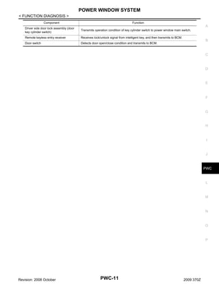
< FUNCTION DIAGNOSIS >
CONSULT screen item
Indication/Unit
Description
A
Vehicle Speed
km/h
Vehicle speed of the moment a particular DTC is detected
Odo/Trip Meter
km
Total mileage (Odometer value) of the moment a particular DTC is detected
SLEEP>LOCK
While turning BCM status from low power consumption mode to
normal mode (Power supply position is “LOCK”)
SLEEP>OFF
While turning BCM status from low power consumption mode to
normal mode (Power supply position is “OFF”.)
LOCK>ACC
While turning power supply position from “LOCK” to “ACC”
ACC>ON
While turning power supply position from “ACC” to “IGN”
RUN>ACC
While turning power supply position from “RUN” to “ACC” (Vehicle
is stopping and selector lever is except P position.)
CRANK>RUN
While turning power supply position from “CRANKING” to “RUN”
(From cranking up the engine to run it)
RUN>URGENT
While turning power supply position from “RUN“ to “ACC” (Emergency stop operation)
ACC>OFF
While turning power supply position from “ACC” to “OFF”
OFF>LOCK
Vehicle Condition
OFF>ACC
ON>CRANK
C
D
E
F
While turning power supply position from “OFF” to “LOCK”
Power position status of
the moment a particular
DTC is detected
While turning power supply position from “OFF” to “ACC”
G
While turning power supply position from “IGN” to “CRANKING”
OFF>SLEEP
While turning BCM status from normal mode (Power supply position is “OFF”.) to low power consumption mode
LOCK>SLEEP
While turning BCM status from normal mode (Power supply position is “LOCK”.) to low power consumption mode
LOCK
Power supply position is “LOCK” (Ignition switch OFF with steering is locked.)
OFF
Power supply position is “OFF” (Ignition switch OFF with steering
is unlocked.)
ACC
Power supply position is “ACC” (Ignition switch ACC)
ON
Power supply position is “IGN” (Ignition switch ON with engine
stopped)
ENGINE RUN
Power supply position is “RUN” (Ignition switch ON with engine
running)
CRANKING
IGN Counter
B
Power supply position is “CRANKING” (At engine cranking)
0 - 39
The number of times that ignition switch is turned ON after DTC is detected
• The number is 0 when a malfunction is detected now.
• The number increases like 1 → 2 → 3...38 → 39 after returning to the normal condition
whenever ignition switch OFF → ON.
• The number is fixed to 39 until the self-diagnosis results are erased if it is over 39.
RETAINED PWR
I
J
PWC
L
M
N
RETAINED PWR : CONSULT-III Function (BCM - RETAINED PWR)
INFOID:0000000004747508
O
Data monitor
Monitor Item
Description
DOOR SW-DR
DOOR SW-AS
P
Indicates [ON/OFF] condition of driver side door switch.
Indicates [ON/OFF] condition of passenger side door switch.
Revision: 2008 October
H
PWC-13
2009 370Z](https://image.slidesharecdn.com/pwc-140302061324-phpapp02/85/Pwc-13-320.jpg)


![BCM (BODY CONTROL MODULE)
< ECU DIAGNOSIS >
Terminal No.
(Wire color)
+
–
Description
Signal name
Condition
Input/
Output
Value
(Approx.)
When Intelligent Key is in
the antenna detection
area
77
(LG)
Ground
Driver door antenna
(+)
Output
When the driver door request
switch is operated with ignition switch
OFF
JMKIA0062GB
When Intelligent Key is not
in the antenna detection
area
JMKIA0063GB
80
(GR)
Ground
NATS antenna amp
(Built in key slot)
Input/
Output
During waiting
Ignition switch is pressed
while inserting the Intelligent Key into the key slot.
Just after pressing ignition
switch. Pointer of tester should
move.
81
(W)
Ground
NATS antenna amp
(Built in key slot)
Input/
Output
During waiting
Ignition switch is pressed
while inserting the Intelligent Key into the key slot.
Just after pressing ignition
switch. Pointer of tester should
move.
82
(R)
Ground
Ignition relay [Fuse
block (J/B)] control
Output
Ignition switch
OFF or ACC
0V
ON
12 V
During waiting
JMKIA0064GB
83
(GR)
Ground
Remote keyless entry
receiver communication
Input/
Output
When operating either button on the Intelligent Key
JMKIA0065GB
Revision: 2008 October
PWC-42
2009 370Z](https://image.slidesharecdn.com/pwc-140302061324-phpapp02/85/Pwc-42-320.jpg)


![BCM (BODY CONTROL MODULE)
< ECU DIAGNOSIS >
Priority
DTC
5
•
•
•
•
•
•
•
•
•
•
•
•
•
•
•
•
•
•
•
•
•
•
•
•
•
C1704: LOW PRESSURE FL
C1705: LOW PRESSURE FR
C1706: LOW PRESSURE RR
C1707: LOW PRESSURE RL
C1708: [NO DATA] FL
C1709: [NO DATA] FR
C1710: [NO DATA] RR
C1711: [NO DATA] RL
C1712: [CHECKSUM ERR] FL
C1713: [CHECKSUM ERR] FR
C1714: [CHECKSUM ERR] RR
C1715: [CHECKSUM ERR] RL
C1716: [PRESSDATA ERR] FL
C1717: [PRESSDATA ERR] FR
C1718: [PRESSDATA ERR] RR
C1719: [PRESSDATA ERR] RL
C1720: [CODE ERR] FL
C1721: [CODE ERR] FR
C1722: [CODE ERR] RR
C1723: [CODE ERR] RL
C1724: [BATT VOLT LOW] FL
C1725: [BATT VOLT LOW] FR
C1726: [BATT VOLT LOW] RR
C1727: [BATT VOLT LOW] RL
C1734: CONTROL UNIT
6
• B2621: INSIDE ANTENNA
• B2622: INSIDE ANTENNA
• B2623: INSIDE ANTENNA
DTC Index
INFOID:0000000004754461
NOTE:
The details of time display are as follows.
• CRNT: A malfunction is detected now.
• PAST: A malfunction was detected in the past.
IGN counter is displayed on Freeze Frame Data. For details of Freeze Frame Data, refer to BCS-17, "COMMON ITEM : CONSULT-III Function (BCM - COMMON ITEM)".
Fail-safe
Freeze Frame Data
•Vehicle Speed
•Odo/Trip Meter
•Vehicle condition
Intelligent Key
warning lamp ON
Tire pressure
monitor warning
lamp ON
Reference page
No DTC is detected.
further testing
may be required.
—
—
—
—
—
U1000: CAN COMM CIRCUIT
—
—
—
—
BCS-38
CONSULT display
U1010: CONTROL UNIT (CAN)
—
—
—
—
BCS-39
U0415: VEHICLE SPEED SIG
—
—
—
—
BCS-40
B2013: ID DISCORD BCM-S/L
×
×
—
—
SEC-50
B2014: CHAIN OF S/L-BCM
×
×
—
—
SEC-51
B2190: NATS ANTENNA AMP
×
—
—
—
SEC-42
B2191: DIFFERENCE OF KEY
×
—
—
—
SEC-45
B2192: ID DISCORD BCM-ECM
×
—
—
—
SEC-46
B2193: CHAIN OF BCM-ECM
×
—
—
—
SEC-48
B2195: ANTI SCANNING
×
—
—
—
SEC-49
B2553: IGNITION RELAY
—
×
—
—
PCS-48
B2555: STOP LAMP
—
×
—
—
SEC-54
Revision: 2008 October
PWC-62
2009 370Z](https://image.slidesharecdn.com/pwc-140302061324-phpapp02/85/Pwc-62-320.jpg)
![BCM (BODY CONTROL MODULE)
< ECU DIAGNOSIS >
Fail-safe
Freeze Frame Data
•Vehicle Speed
•Odo/Trip Meter
•Vehicle condition
Intelligent Key
warning lamp ON
Tire pressure
monitor warning
lamp ON
Reference page
A
B2556: PUSH-BTN IGN SW
—
×
×
—
SEC-56
B
B2557: VEHICLE SPEED
×
×
×
—
SEC-58
B2560: STARTER CONT RELAY
×
×
×
—
SEC-59
B2562: LOW VOLTAGE
—
×
—
—
BCS-41
B2601: SHIFT POSITION
×
×
×
—
SEC-60
B2602: SHIFT POSITION
×
×
×
—
SEC-63
B2603: SHIFT POSI STATUS
×
×
×
—
SEC-66
B2604: PNP SW
×
×
×
—
SEC-69
B2605: PNP SW
×
×
×
—
SEC-71
B2606: S/L RELAY
×
×
×
—
SEC-73
B2607: S/L RELAY
×
×
×
—
SEC-74
B2608: STARTER RELAY
×
×
×
—
SEC-76
B2609: S/L STATUS
×
×
×
—
SEC-78
B260A: IGNITION RELAY
×
×
×
—
PCS-50
B260B: STEERING LOCK UNIT
—
×
×
—
SEC-82
B260C: STEERING LOCK UNIT
—
×
×
—
SEC-83
B260D: STEERING LOCK UNIT
—
×
×
—
SEC-84
B260F: ENG STATE SIG LOST
×
×
×
—
SEC-85
B2612: S/L STATUS
×
×
×
—
SEC-90
B2614: ACC RELAY CIRC
—
×
×
—
PCS-52
B2615: BLOWER RELAY CIRC
—
×
×
—
PCS-55
B2616: IGN RELAY CIRC
—
×
×
—
PCS-58
B2617: STARTER RELAY CIRC
×
×
×
—
SEC-94
B2618: BCM
×
×
×
—
PCS-61
B2619: BCM
×
×
×
—
SEC-96
B261A: PUSH-BTN IGN SW
—
×
×
—
PCS-62
—
SEC-97
CONSULT display
C
D
E
F
G
H
I
J
PWC
L
B261E: VEHICLE TYPE
×
×
× (Turn ON for 15
seconds)
B2622: INSIDE ANTENNA
—
×
—
—
DLK-55
B2623: INSIDE ANTENNA
—
×
—
—
DLK-57
B26E8: CLUTCH SW
×
×
×
—
SEC-86
B26E9: S/L STATUS
×
×
× (Turn ON for 15
seconds)
—
SEC-88
B26EA: KEY REGISTRATION
—
×
× (Turn ON for 15
seconds)
—
SEC-89
C1704: LOW PRESSURE FL
—
—
—
×
C1705: LOW PRESSURE FR
—
—
—
×
C1706: LOW PRESSURE RR
—
—
—
×
C1707: LOW PRESSURE RL
—
—
—
×
C1708: [NO DATA] FL
—
—
—
×
C1709: [NO DATA] FR
—
—
—
×
C1710: [NO DATA] RR
—
—
—
×
C1711: [NO DATA] RL
—
—
—
×
Revision: 2008 October
PWC-63
M
N
O
WT-15
WT-17
2009 370Z
P](https://image.slidesharecdn.com/pwc-140302061324-phpapp02/85/Pwc-63-320.jpg)
![BCM (BODY CONTROL MODULE)
< ECU DIAGNOSIS >
Fail-safe
Freeze Frame Data
•Vehicle Speed
•Odo/Trip Meter
•Vehicle condition
Intelligent Key
warning lamp ON
Tire pressure
monitor warning
lamp ON
C1712: [CHECKSUM ERR] FL
—
—
—
×
C1713: [CHECKSUM ERR] FR
—
—
—
×
C1714: [CHECKSUM ERR] RR
—
—
—
×
C1715: [CHECKSUM ERR] RL
—
—
—
×
C1716: [PRESSDATA ERR] FL
—
—
—
×
C1717: [PRESSDATA ERR] FR
—
—
—
×
C1718: [PRESSDATA ERR] RR
—
—
—
×
C1719: [PRESSDATA ERR] RL
—
—
—
×
C1720: [CODE ERR] FL
—
—
—
×
C1721: [CODE ERR] FR
—
—
—
×
C1722: [CODE ERR] RR
—
—
—
×
C1723: [CODE ERR] RL
—
—
—
×
C1724: [BATT VOLT LOW] FL
—
—
—
×
C1725: [BATT VOLT LOW] FR
—
—
—
×
C1726: [BATT VOLT LOW] RR
—
—
—
×
C1727: [BATT VOLT LOW] RL
—
—
—
×
C1729: VHCL SPEED SIG ERR
—
—
—
×
WT-31
C1734: CONTROL UNIT
—
—
—
×
WT-33
CONSULT display
Revision: 2008 October
PWC-64
Reference page
WT-20
WT-23
WT-25
WT-28
2009 370Z](https://image.slidesharecdn.com/pwc-140302061324-phpapp02/85/Pwc-64-320.jpg)
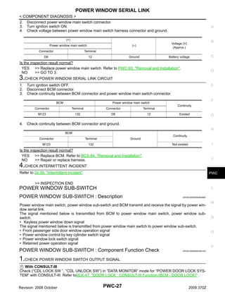
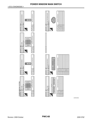
![POWER WINDOW MAIN SWITCH
< ECU DIAGNOSIS >
POWER WINDOW MAIN SWITCH
A
Reference Value
INFOID:0000000004461030
TERMINAL LAYOUT
B
PHYSICAL VALUES
C
D
JMKIA1191ZZ
E
POWER WINDOW MAIN SWITCH
Terminal No.
(Wire color)
F
Description
Voltage [V]
(Approx.)
+
-
1
(W)
Ground
Battery power supply
Input
5
(O)
Ground
Encoder power supply
Output
6
(GR)
Ground
Door key cylinder switch
LOCK signal
Input
Key position
(Neutral → Locked)
5→0
7
(V)
Ground
Door key cylinder switch UNLOCK signal
Input
Key position
(Neutral → Unlocked)
5→0
Ground
Driver side power window
motor UP signal
Output
When power window main
switch (Driver side) is operated UP
Battery voltage
8
(L)
Signal name
Condition
Input/
Output
G
—
When ignition switch ON
or automatic window adjusting operates
Battery voltage
H
Battery voltage
I
J
PWC
9
(LG)
Ground
Encoder pulse signal 2
Input
L
When power window motor operates
JMKIA0070GB
10
(Y)
11
(BR)
12
(SB)
Ground
Ground
Ground
Ignition switch power signal
Driver side power window
motor DOWN signal
Power window serial link
Input
Output
Input/
Output
IGN SW ON
Battery voltage
IGN SW OFF
0
When power window main
switch (Driver side) is operated DOWN
N
Battery voltage
O
P
Ignition switch ON
JPMIA0013GB
Revision: 2008 October
M
PWC-65
2009 370Z](https://image.slidesharecdn.com/pwc-140302061324-phpapp02/85/Pwc-65-320.jpg)
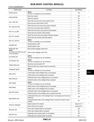
![POWER WINDOW MAIN SWITCH
< ECU DIAGNOSIS >
Terminal No.
(Wire color)
+
-
13
(R)
Ground
Description
Signal name
Encoder pulse signal 1
Condition
Input/
Output
Input
Voltage [V]
(Approx.)
When power window motor operates
JMKIA0070GB
14
(G)
Ground
Encoder ground
—
—
0
15
(B)
Ground
Ground
—
—
0
Revision: 2008 October
PWC-66
2009 370Z](https://image.slidesharecdn.com/pwc-140302061324-phpapp02/85/Pwc-66-320.jpg)


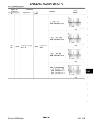
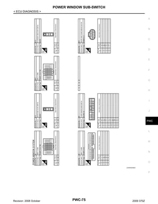
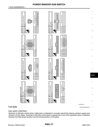
![POWER WINDOW SUB-SWITCH
< ECU DIAGNOSIS >
POWER WINDOW SUB-SWITCH
Reference Value
INFOID:0000000004461033
TERMINAL LAYOUT
JMKIA0134ZZ
PHYSICAL VALUES
Terminal No.
(Wire color)
Description
Signal name
Condition
Voltage [V]
(Approx.)
—
Input/
Output
0
+
-
3
(G)
Ground
Encoder ground
4
(O)
Ground
Encoder power supply
Output
When ignition switch ON or
automatic window operates
adjusting
Battery voltage
8
(L)
Ground
Power window motor
UP signal
Output
When power window motor is
operated UP
Battery voltage
9
(BR)
Ground
Power window motor
DOWN signal
Output
When power window motor is
operated DOWN
Battery voltage
10
(W)
Ground
Battery power supply
Input
—
Battery voltage
11
(B)
Ground
Ground
—
—
0
12
(R)
Ground
Encoder pulse signal 1
—
Input
When power window motor
operates
JMKIA0070GB
Revision: 2008 October
PWC-72
2009 370Z](https://image.slidesharecdn.com/pwc-140302061324-phpapp02/85/Pwc-72-320.jpg)
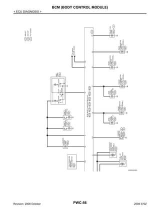
![POWER WINDOW SUB-SWITCH
< ECU DIAGNOSIS >
Terminal No.
(Wire color)
+
Description
-
Signal name
Condition
Input/
Output
A
Voltage [V]
(Approx.)
B
15
(LG)
Ground
Encoder pulse signal 2
Input
When power window motor
operates
C
JMKIA0070GB
D
E
16
(Y)
Ground
Power window serial link
Input/
Output
Ignition switch ON
F
JPMIA0013GB
G
H
I
J
PWC
L
M
N
O
P
Revision: 2008 October
PWC-73
2009 370Z](https://image.slidesharecdn.com/pwc-140302061324-phpapp02/85/Pwc-73-320.jpg)


The document provides information on diagnosing issues with a vehicle's power window control system. It includes: 1) A system diagram showing the components of the power window control system including the BCM, power window switches, motors and encoders. 2) A description of the system including functions like auto-open/close, anti-pinch, retained power operation and use of serial communication between components. 3) Sections on inspecting individual components, performing diagnostics, addressing specific symptoms, and precautions for repairs. The document provides a thorough overview of analyzing and troubleshooting power window problems.