Download to read offline


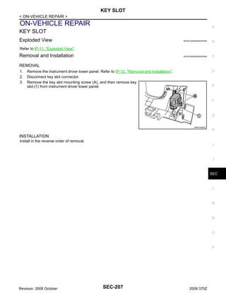
![INTELLIGENT KEY SYSTEM/ENGINE START FUNCTION
< FUNCTION DIAGNOSIS >
FUNCTION DIAGNOSIS
A
INTELLIGENT KEY SYSTEM/ENGINE START FUNCTION
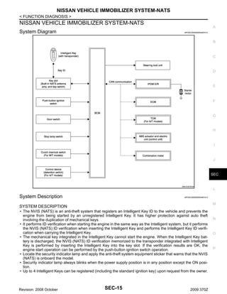
System Diagram
INFOID:0000000004497408
B
C
D
E
F
G
H
I
J
SEC
L
JMKIA3450GB
System Description
INFOID:0000000004497409
M
SYSTEM DESCRIPTION
• The engine start function of Intelligent Key system is a system that makes it possible to start and stop the
engine without removing the key. It verifies an electronic ID using two-way communication when pressing
the push-button ignition switch while carrying the Intelligent Key, which operates based on the results of
electronic ID verification of Intelligent Key using two-way communication between the Intelligent Key and the
vehicle.
NOTE:
The driver should carry the Intelligent Key at all times.
• Intelligent Key has 2 IDs [Intelligent Key and NVIS (NATS)]. It can perform the door lock/unlock operation
and the push-button ignition switch operation when the registered Intelligent Key is carried.
• When the Intelligent Key battery is discharged, it can be used as emergency back-up by inserting the Intelligent Key to the key slot. At that time, perform the NVIS (NATS) ID verification. If it is used when the Intelligent Key is carried, perform the Intelligent Key ID verification.
• If the ID is successfully verified, when push-button ignition switch is pressed, steering lock is released and
the engine can be started.
Revision: 2008 October
SEC-9
2009 370Z
N
O
P](https://image.slidesharecdn.com/sec-140302061344-phpapp01/85/Sec-9-320.jpg)
![INTELLIGENT KEY SYSTEM/ENGINE START FUNCTION
< FUNCTION DIAGNOSIS >
• Up to 4 Intelligent Keys can be registered (Including the standard Intelligent Key) upon request from the customer.
NOTE:
Refer to DLK-15, "INTELLIGENT KEY SYSTEM : System Description" for any functions other than engine
start function of Intelligent Key system.
PRECAUTIONS FOR INTELLIGENT KEY SYSTEM
In the Intelligent Key system, the transponder [the chip for NVIS (NATS) ID verification] is integrated
into the Intelligent Key. (For the conventional models, it is integrated into the mechanical key.) Therefore, the mechanical key cannot perform ID verification, and thus it cannot start the engine. Instead,
NVIS (NATS) ID verification can be performed by inserting the Intelligent Key to the key slot, and then
it can start the engine.
OPERATION WHEN INTELLIGENT KEY IS CARRIED
1.
When the push-button ignition switch is pressed, the BCM activates the inside key antenna and transmits
the request signal to the Intelligent Key.
2. The Intelligent Key receives the request signal and transmits the Intelligent Key ID signal to the BCM via
the remote keyless entry receiver.
3. The Intelligent Key receives the Intelligent Key ID signal and verifies it with the registered ID.
4. BCM transmits the steering lock unlock signal to steering lock unit and IPDM E/R if the verification results
are OK.
5. IPDM E/R turns the steering lock relay ON and supplies power supply to the steering lock unit.
6. The steering lock releases.
7. BCM transmits the power supply stop signal to IPDM E/R when detecting that the steering lock is in the
unlock condition.
8. IPDM E/R turns the steering lock relay OFF and stops power supply to the steering lock unit.
9. BCM turns ACC relay ON and transmits the ignition power supply ON signal to IPDM E/R.
10. IPDM E/R turns the ignition relay ON and starts the ignition power supply.
11. BCM detects that the selector lever position and brake pedal operating condition (A/T models), or shift
lever position and clutch pedal operation condition (M/T models).
12. BCM transmits the starter request signal via CAN communication to IPDM E/R and turns the starter relay
in IPDM E/R ON if BCM judges that the engine start condition is satisfied.
13. IPDM E/R turns the starter control relay ON when receiving the starter request signal.
14. Power supply is supplied through the starter relay and the starter control relay to operate the starter motor
and start cranking.
CAUTION:
If a malfunction is detected in the Intelligent Key system, the “KEY” warning lamp in the combination meter illuminates. At that time, the engine cannot be started.
15. When BCM receives feedback signal from ECM indicating that the engine is started, the BCM transmits a
stop signal to IPDM E/R and stops cranking by turning OFF the starter motor relay. (If engine start is
unsuccessful, cranking stops automatically within 5 seconds.)
CAUTION:
When the Intelligent Key is carried outside of the vehicle (inside key antenna detection area) while
the power supply is in the ACC or ON position, even if the engine start condition* is satisfied, the
engine cannot be started.
*: For the engine start condition, refer to “PUSH-BUTTON IGNITION SWITCH OPERATION PROCEDURE”.
OPERATION RANGE
Engine can be started when Intelligent Key is inside the vehicle. However, sometimes engine may not start
when Intelligent Key is on instrument panel or in glove box.
OPERATION WHEN KEY SLOT IS USED
When the Intelligent Key battery is discharged, it performs NVIS (NATS) ID verification between the integrated
transponder and BCM by inserting the Intelligent Key into the key slot, and then the engine can be started.
For details relating to starting the engine using key slot, refer to SEC-15, "System Description".
BATTERY SAVER SYSTEM
When all the following conditions are met for 60 minutes, the battery saver system cuts off the power supply to
prevent battery discharge.
Revision: 2008 October
SEC-10
2009 370Z](https://image.slidesharecdn.com/sec-140302061344-phpapp01/85/Sec-10-320.jpg)


![DIAGNOSIS SYSTEM (BCM)
< FUNCTION DIAGNOSIS >
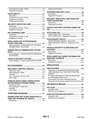
Monitor item
Description
LOCK/UNLOCK BY I-KEY
Door lock/unlock function by door request switch (driver side, passenger side and back door)
mode can be changed to operate (ON) or not operate (OFF) in this mode.
ENGINE START BY I-KEY
Engine start function mode can be changed to operate (ON) or not operate (OFF) with this
mode.
TRUNK/GLASS HATCH OPEN
Buzzer reminder function mode by back door request switch can be changed to operate (ON)
or not operate (OFF) with this mode.
PANIC ALARM SET
Panic alarm button pressing time on Intelligent Key remote control button can be selected from
the following with this mode.
• MODE 1: 0.5 sec.
• MODE 2: Non-operation
• MODE 3: 1.5 sec.
TAKE OUT FROM WIN WARN
NOTE:
This item is displayed, but cannot be monitored.
PW DOWN SET
Unlock button pressing time on Intelligent Key button can be selected from the following with
this mode.
• MODE 1: 3 sec.
• MODE 2: Non-operation
• MODE 3: 5 sec.
TRUNK OPEN DELAY
NOTE:
This item is displayed, but cannot be supported.
LO- BATT OF KEY FOB WARN
Intelligent Key low battery warning mode can be changed to operate (ON) or not operate
(OFF) with this mode.
ANTI KEY LOCK IN FUNCTI
Key reminder function mode can be changed to operate (ON) or not operate (OFF) with this
mode.
HAZARD ANSWER BACK
Hazard reminder function mode can be selected from the following with this mode.
• LOCK ONLY: Door lock operation only
• UNLOCK ONLY: Door unlock operation only
• LOCK/UNLOCK: Lock/unlock operation
• OFF: Non-operation
ANS BACK I-KEY LOCK
Buzzer reminder function (lock operation) mode by door request switch (driver side and passenger side) can be selected from the following with this mode.
• Horn chirp: Sound horn
• Buzzer: Sound Intelligent Key warning buzzer
• OFF: Non-operation
ANS BACK I-KEY UNLOCK
Buzzer reminder function (unlock operation) mode by door request switch can be changed to
operate (ON) or not operate (OFF) with this mode.
SHORT CRANKING OUTPUT
Starter motor can be forcibly activated.
INSIDE ANT DIAGNOSIS
This function allows inside key antenna self-diagnosis.
HORN WITH KEYLESS LOCK
Horn reminder function mode by Intelligent Key button can be changed to operate (ON) or not
operate (OFF) with this mode.
SELF-DIAG RESULT
Refer to DLK-155, "DTC Index".
DATA MONITOR
Monitor Item
Condition
REQ SW -DR
Indicates [ON/OFF] condition of door request switch (driver side).
REQ SW -AS
Indicates [ON/OFF] condition of door request switch (passenger side).
REQ SW -BD/TR
Indicates [ON/OFF] condition of back door request switch.
PUSH SW
Indicates [ON/OFF] condition of push-button ignition switch.
IGN RLY2 -F/B
Indicates [ON/OFF] condition of ignition relay 2.
ACC RLY-F/B
NOTE:
This item is displayed, but cannot be monitored.
Revision: 2008 October
SEC-26
2009 370Z](https://image.slidesharecdn.com/sec-140302061344-phpapp01/85/Sec-26-320.jpg)
![DIAGNOSIS SYSTEM (BCM)
< FUNCTION DIAGNOSIS >
Monitor Item
Condition
CLUCH SW*1
BRAKE SW 1
Indicates [ON/OFF]*2 condition of brake switch power supply.
BRAKE SW 2
Indicates [ON/OFF] condition of brake switch.
DETE/CANCL SW
Indicates [ON/OFF] condition of P position.
SFT PN/N SW
Indicates [ON/OFF] condition of P or N position.
S/L -LOCK
Indicates [ON/OFF] condition of steering lock unit (LOCK).
S/L -UNLOCK
Indicates [ON/OFF] condition of steering lock unit (UNLOCK).
S/L RELAY -F/B
Indicates [ON/OFF] condition of steering lock relay.
UNLK SEN -DR
Indicates [ON/OFF] condition of driver door UNLOCK status.
PUSH SW -IPDM
Indicates [ON/OFF] condition of push-button ignition switch.
IGN RLY1 -F/B
Indicates [ON/OFF] condition of ignition relay 1.
DETE SW -IPDM
A
Indicates [ON/OFF] condition of clutch switch.
Indicates [ON/OFF] condition of P position.
B
C
D
E
SFT PN -IPDM
Indicates [ON/OFF] condition of P or N position.
SFT P -MET
Indicates [ON/OFF] condition of P position.
SFT N -MET
Indicates [ON/OFF] condition of N position.
ENGINE STATE
Indicates [STOP/STALL/CRANK/RUN] condition of engine states.
S/L LOCK-IPDM
Indicates [ON/OFF] condition of steering lock unit (LOCK).
S/L UNLK-IPDM
Indicates [ON/OFF] condition of steering lock unit (UNLOCK).
S/L RELAY-REQ
Indicates [ON/OFF] condition of steering lock relay.
VEH SPEED 1
Display the vehicle speed signal received from combination meter by numerical value [km/h].
VEH SPEED 2
Display the vehicle speed signal received from ABS or VDC or TCM by numerical value [km/h].
DOOR STAT-DR
Indicates [LOCK/READY/UNLOCK] condition of driver side door status.
DOOR STAT-AS
Indicates [LOCK/READY/UNLOCK] condition of passenger side door status.
ID OK FLAG
Indicates [SET/RESET] condition of key ID.
PRMT ENG STRT
Indicates [SET/RESET] condition of engine start possibility.
PRMT RKE STRT
NOTE:
This item is displayed, but cannot be monitored.
KEY SW -SLOT
Indicates [ON/OFF] condition of key slot.
TRNK/HAT MNTR
NOTE:
This item is displayed, but cannot be monitored.
RKE-LOCK
Indicates [ON/OFF] condition of LOCK signal from Intelligent Key.
RKE-UNLOCK
Indicates [ON/OFF] condition of UNLOCK signal from Intelligent Key.
RKE-TR/BD
NOTE:
This item is displayed, but cannot be monitored.
RKE-PANIC
Indicates [ON/OFF] condition of PANIC button of Intelligent Key.
RKE-P/W OPEN
Indicates [ON/OFF] condition of P/W DOWN signal from Intelligent Key.
RKE-MODE CHG
Indicates [ON/OFF] condition of MODE CHANGE signal from Intelligent Key.
RKE OPE COUN1
When remote keyless entry receiver receives the signal transmitted while operating on Intelligent Key, the numerical value start changing.
RKE OPE COUN2
NOTE:
This item is displayed, but cannot be monitored.
F
G
H
J
SEC
L
M
N
O
P
*1: It is displayed but does not operate on M/T models.
*2: OFF is displayed when brake pedal is depressed while brake switch power supply is OFF.
ACTIVE TEST
Revision: 2008 October
SEC-27
I
2009 370Z](https://image.slidesharecdn.com/sec-140302061344-phpapp01/85/Sec-27-320.jpg)

![DIAGNOSIS SYSTEM (BCM)
< FUNCTION DIAGNOSIS >
THEFT ALM : CONSULT-III Function (BCM - THEFT)
INFOID:0000000004497422
A
DATA MONITOR
Monitored Item
B
Description
REQ SW -DR
Indicates [ON/OFF] condition of door request switch (driver side).
REQ SW -AS
Indicates [ON/OFF] condition of door request switch (passenger side).
REQ SW -RR
NOTE:
This is displayed even when it is not equipped.
REQ SW -RL
NOTE:
This is displayed even when it is not equipped.
REQ SW -BD/TR
Indicates [ON/OFF] condition of back door request switch.
PUSH SW
Indicates [ON/OFF] condition of push-button ignition switch
UNLK SEN -DR
Indicates [ON/OFF] condition of driver door UNLOCK status.
KEY SW -SLOT
Indicates [ON/OFF] condition of key slot.
DOOR SW-DR
Indicates [ON/OFF] condition of driver side door switch.
DOOR SW-AS
Indicates [ON/OFF] condition of passenger side door switch.
DOOR SW-RR
NOTE:
This is displayed even when it is not equipped.
DOOR SW-RL
NOTE:
This is displayed even when it is not equipped.
DOOR SW-BK
Indicates [ON/OFF] condition of back door switch.
C
D
E
F
G
H
CDL LOCK SW
Indicates [ON/OFF] condition of lock signal from door lock/unlock switch LH and RH.
CDL UNLOCK SW
Indicates [ON/OFF] condition of unlock signal from door lock/unlock switch LH and RH.
TR/BD OPEN SW
Indicates [ON/OFF] condition of back door opener switch.
TRNK/HAT MNTR
Indicates [ON/OFF] condition of back door.
RKE-LOCK
Indicates [ON/OFF] condition of LOCK signal from Intelligent Key.
RKE-UNLOCK
Indicates [ON/OFF] condition of UNLOCK signal from Intelligent Key.
RKE-TR/BD
NOTE:
This is displayed even when it is not equipped.
I
J
SEC
WORK SUPPORT
L
Test Item
Description
SECURITY ALARM SET
This mode is able to confirm and change security alarm ON-OFF setting.
THEFT ALM TRG
The switch which triggered vehicle security alarm is recorded.
This mode is able to confirm and erase the record of vehicle security alarm.
The trigger data can be erased by touching “CLEAR” on CONSULT-III screen.
M
N
ACTIVE TEST
Test Item
Description
THEFT IND
This test is able to check security indicator lamp operation. The lamp is turned on when “ON” on
CONSULT-III screen is touched.
VEHICLE SECURITY HORN
This test is able to check vehicle security horn operation. The horns are activated for 0.5 seconds
after “ON” on CONSULT-III screen is touched.
HEADLAMP(HI)
This test is able to check vehicle security lamp operation. The headlamps are activated for 0.5 seconds after “ON” on CONSULT-III screen is touched.
FLASHER
This test is able to check vehicle security hazard lamp operation. The hazard lamps are activated
after “ON” on CONSULT-III screen is touched.
IMMU
Revision: 2008 October
SEC-29
2009 370Z
O
P](https://image.slidesharecdn.com/sec-140302061344-phpapp01/85/Sec-29-320.jpg)
![DIAGNOSIS SYSTEM (BCM)
< FUNCTION DIAGNOSIS >
IMMU : CONSULT-III Function (BCM - IMMU)
INFOID:0000000004497423
DATA MONITOR
Monitor item
Content
CONFRM ID ALL
CONFIRM ID4
CONFIRM ID3
Indicates [YET] at all time.
Switches to [DONE] when a registered Intelligent Key is inserted into the key slot.
CONFIRM ID2
CONFIRM ID1
TP 4
TP 3
Indicates the number of IDs that are registered.
TP 2
TP 1
PUSH SW
Indicates [ON/OFF] condition of push-button ignition switch.
KEY SW -SLOT
Indicates [ON/OFF] condition of key slot.
ACTIVE TEST
Test item
THEFT IND
Revision: 2008 October
Description
This test is able to check security indicator lamp operation.
The lamp is turned on when “ON” on CONSULT-III screen touched.
SEC-30
2009 370Z](https://image.slidesharecdn.com/sec-140302061344-phpapp01/85/Sec-30-320.jpg)


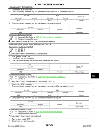


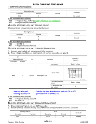

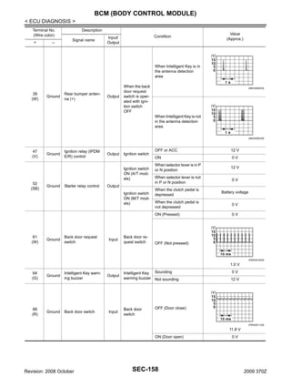
![B2555 STOP LAMP
< COMPONENT DIAGNOSIS >
B2555 STOP LAMP
Description
INFOID:0000000004497467
BCM detects the stop lamp status and confirms the stop lamp switch ON/OFF status. BCM confirms the
engine start condition according to the stop lamp switch ON/OFF status.
DTC Logic
INFOID:0000000004497468
DTC DETECTION LOGIC
DTC No.
B2555
Trouble diagnosis name
Possible cause
BCM makes a comparison between the
upper voltage and lower voltage of stop
lamp switch. It judges from their values to
detect the malfunctioning circuit.
STOP LAMP
DTC detecting condition
• Harness or connectors
(stop lamp switch circuit is open or shorted)
• Stop lamp switch
• Fuse
DTC CONFIRMATION PROCEDURE
1.PERFORM DTC CONFIRMATION PROCEDURE
1. Depress the brake pedal and wait 1 second or more.
2. Check “Self-diagnostic result” using CONSULT-III.
Is DTC detected?
YES >> Go to SEC-54, "Diagnosis Procedure".
NO
>> INSPECTION END
Diagnosis Procedure
INFOID:0000000004497469
1.CHECK STOP LAMP SWITCH INPUT SIGNAL
1.
2.
3.
Turn ignition switch OFF.
Disconnect BCM connector.
Check voltage between BCM harness connector and ground.
(+)
(–)
Connector
116
Battery voltage
Terminal
M123
Voltage (V)
(Approx.)
Ground
BCM
Is the inspection normal?
YES >> GO TO 2.
NO-1 >> Check 10 A fuse [No. 7, located in the fuse block (J/B)].
NO-2 >> Check harness for open or short between BCM and fuse.
2.CHECK STOP LAMP SWITCH POWER SUPPLY CIRCUIT
1.
2.
Disconnect stop lamp switch connector.
Check voltage between stop lamp harness connector and ground.
(+)
(–)
Connector
1
Battery voltage
Terminal
E110
Voltage (V)
(Approx.)
Ground
Stop lamp switch
Is the inspection result normal?
YES >> GO TO 3.
NO
>> Check harness for open or short to stop lamp switch.
3.CHECK STOP LAMP SWITCH CIRCUIT
Revision: 2008 October
SEC-54
2009 370Z](https://image.slidesharecdn.com/sec-140302061344-phpapp01/85/Sec-54-320.jpg)


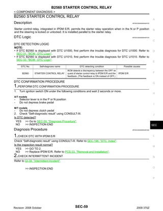


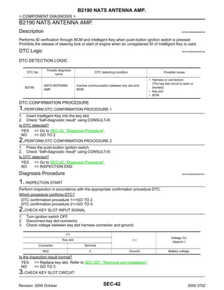
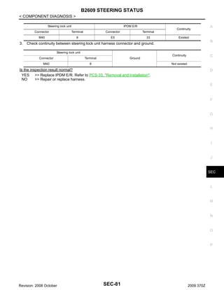
![B2609 STEERING STATUS
< COMPONENT DIAGNOSIS >
B2609 STEERING STATUS
Description
INFOID:0000000004497506
There are 2 switches in the steering lock unit (steering lock/unlock switch 1 and 2). BCM compares the 2
switch conditions to judge the present steering status.
DTC Logic
INFOID:0000000004497507
DTC DETECTION LOGIC
NOTE:
• If DTC B2609 is displayed with DTC U1000, first perform the trouble diagnosis for DTC U1000. Refer to
SEC-31, "BCM : DTC Logic".
• If DTC B2609 is displayed with DTC U1010, first perform the trouble diagnosis for DTC U1010. Refer to
SEC-33, "BCM : DTC Logic".
DTC No.
B2609
Trouble diagnosis
name
STEERING STATUS
DTC detecting condition
BCM detects the malfunction of steering lock unit
switches for 1 second.
Possible cause
• Harness or connectors
[Steering lock unit circuit (BCM
side) is open or shorted]
• Harness or connectors
[Steering lock unit circuit (IPDM E/
R side) is open or shorted]
• Steering lock unit
• IPDM E/R
DTC CONFIRMATION PROCEDURE
1.PERFORM DTC CONFIRMATION PROCEDURE-1
1.
Turn ignition switch ON under the following conditions.
A/T models
-
Selector lever is in the P or N position
Do not depress brake pedal
M/T models
Do not depress clutch pedal
2. Check “Self-diagnostic result” using CONSULT-III.
Is DTC detected?
YES >> Go to SEC-78, "Diagnosis Procedure".
NO
>> GO TO 2.
2.PERFORM DTC CONFIRMATION PROCEDURE-2
1. Turn ignition switch ON.
2. Turn ignition switch OFF.
3. Press driver side door switch and wait 1second or more.
4. Check “Self-diagnostic result” using CONSULT-III.
Is DTC detected?
YES >> Go to SEC-78, "Diagnosis Procedure".
NO
>> INSPECTION END
Diagnosis Procedure
INFOID:0000000004497508
1.INSPECTION START
Perform inspection in accordance with procedure that confirms DTC.
Which procedure confirms DTC?
DTC confirmation procedure 1>>GO TO 2.
DTC confirmation procedure 2>>GO TO 6.
Revision: 2008 October
SEC-78
2009 370Z](https://image.slidesharecdn.com/sec-140302061344-phpapp01/85/Sec-78-320.jpg)


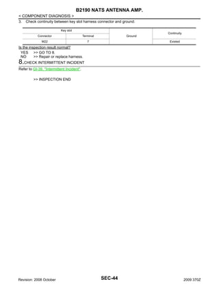
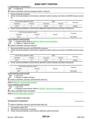
![B26E8 CLUTCH INTERLOCK SWITCH
< COMPONENT DIAGNOSIS >
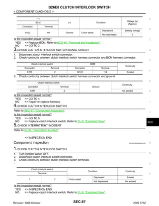
B26E8 CLUTCH INTERLOCK SWITCH
Description
INFOID:0000000004497521
When clutch interlock switch turns ON, BCM detects that clutch pedal is being depressed and permits to start
the engine.
DTC Logic
INFOID:0000000004497522
NOTE:
If DTC B26E8 is displayed with DTC B210F, first perform the trouble diagnosis for DTC B210F. Refer to SEC112, "DTC Logic".
DTC DETECTION LOGIC
DTC No.
B26E8
Trouble diagnosis name
CLUTCH INTERLOCK
SWITCH
DTC detection condition
Possible cause
Detects that ASCD cancel switch is in the ON
position for 2 seconds or more while ignition
switch and clutch interlock switch are ON.
• Clutch interlock switch
• Harness or connector
(Clutch interlock switch circuit
open or shorted)
DTC CONFIRMATION PROCEDURE
1.PERFORM DTC CONFIRMATION PROCEDURE
1. Turn ignition switch ON under the following condition.
Shift lever is in the neutral position.
Depress clutch pedal.
2. Check “Self-diagnostic result” using CONSULT-III.
Is DTC detected?
YES >> Go to SEC-86, "Diagnosis Procedure".
NO
>> INSPECTION END
Diagnosis Procedure
INFOID:0000000004497523
1.CHECK CLUTCH INTERLOCK SWITCH POWER SUPPLY
1.
2.
3.
Turn ignition switch OFF.
Disconnect clutch interlock switch connector.
Check voltage between clutch interlock switch harness connector and ground.
(+)
(–)
Voltage (V)
(Approx.)
Ground
Battery voltage
Clutch interlock switch
Connector
Terminal
E111
1
Is the inspection result normal?
YES >> GO TO 2.
NO-1 >> Check 10 A fuse [No. 9, located in the fuse block (J/B)]
NO-2 >> Check harness for open or short between clutch interlock switch and fuse.
2.CHECK CLUTCH INTERLOCK SWITCH SIGNAL
1.
2.
3.
Connect clutch interlock switch connector.
Disconnect BCM connector.
Check voltage between BCM harness connector and ground.
Revision: 2008 October
SEC-86
2009 370Z](https://image.slidesharecdn.com/sec-140302061344-phpapp01/85/Sec-86-320.jpg)


![B2612 STEERING STATUS
< COMPONENT DIAGNOSIS >
B2612 STEERING STATUS
Description
INFOID:0000000004497531
There are 2 switches in the steering unit. IPDM E/R compares the 2 switch conditions to judge the present
steering status and transmits the result to BCM via CAN communication.
DTC Logic
INFOID:0000000004497532
DTC DETECTION LOGIC
NOTE:
• If DTC B2612 is displayed with DTC U1000, first perform the trouble diagnosis for DTC U1000. Refer to
SEC-31, "BCM : DTC Logic".
• If DTC B2612 is displayed with DTC U1010, first perform the trouble diagnosis for DTC U1010. Refer to
SEC-33, "BCM : DTC Logic".
DTC No.
B2612
Self-diagnosis name
STEERING STATUS
DTC detecting condition
Possible causes
BCM detects the difference between
the following status for 1 second
• Steering lock or unlock
• Feedback of steering lock status from
IPDM E/R (CAN)
• Harness or connectors
[Steering lock unit circuit (BCM side) is
open or shorted]
• Harness or connectors
[Steering lock unit circuit (IPDM E/R side)
is open or shorted]
• Steering lock unit
• IPDM E/R
DTC CONFIRMATION PROCEDURE
1.PERFORM DTC CONFIRMATION PROCEDURE-1
1.
Turn ignition switch ON under the following conditions.
A/T models
-
Selector lever is in the P or N position
Do not depress brake pedal
M/T models
Do not depress clutch pedal
2. Check “Self-diagnostic result” using CONSULT-III.
Is DTC detected?
YES >> Go to SEC-90, "Diagnosis Procedure".
NO
>> GO TO 2.
2.PERFORM DTC CONFIRMATION PROCEDURE-2
1. Turn ignition switch ON.
2. Turn ignition switch OFF.
3. Press door switch.
4. Check “Self-diagnostic result” using CONSULT-III.
Is DTC detected?
YES >> Go to SEC-90, "Diagnosis Procedure".
NO
>> INSPECTION END
Diagnosis Procedure
INFOID:0000000004497533
1.INSPECTION START
Perform inspection in accordance with procedure that confirms DTC.
Which procedure confirms DTC?
DTC confirmation procedure 1>>GO TO 2.
DTC confirmation procedure 2>>GO TO 6.
2.CHECK BCM OUTPUT SIGNAL-1
Revision: 2008 October
SEC-90
2009 370Z](https://image.slidesharecdn.com/sec-140302061344-phpapp01/85/Sec-90-320.jpg)


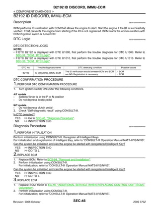
![B261F ASCD CLUTCH SWITCH
< COMPONENT DIAGNOSIS >
B261F ASCD CLUTCH SWITCH
Description
INFOID:0000000004553753
BCM judges that clutch pedal is operated by clutch interlock switch and clutch pedal position switch operation.
DTC Logic
INFOID:0000000004553754
DTC DETECTION LOGIC
DTC No.
Trouble diagnosis name
Possible cause
ASCD CNCL/CLTH SW
B261F
DTC detection condition
When ignition switch is ON and vehicle speed
is 40 km/h, BCM detects that clutch pedal position switch is ON for 10 seconds or more.
• Harness or connector
(ASCD clutch switch circuit open
or shorted)
• Clutch pedal position switch
• BCM
DTC CONFIRMATION PROCEDURE
1.PERFORM DTC CONFIRMATION PROCEDURE
1. Drive the vehicle at the vehicle speed of 40 km/h (24.8 MPH) or more wait 10 seconds or more.
2. Check “Self-diagnostic result” using CONSULT-III.
Is DTC detected?
YES >> Go to SEC-98, "Diagnosis Procedure".
NO
>> INSPECTION END
Diagnosis Procedure
INFOID:0000000004553755
1.CHECK CLUTCH PEDAL POSITION SWITCH POWER SUPPLY
1.
2.
3.
4.
Turn ignition switch OFF.
Disconnect clutch pedal position switch connector.
Turn ignition switch ON.
Check voltage between clutch pedal position switch harness connector and ground.
(+)
(–)
Voltage (V)
(Approx.)
Ground
Battery voltage
Clutch pedal position switch
Connector
Terminal
E108
1
Is the inspection result normal?
YES >> GO TO 2.
NO-1 >> Check 10 A fuse [No. 3, located in the fuse block (J/B)]
NO-2 >> Check harness for open or short between clutch pedal position switch and fuse.
2.CHECK CLUTCH PEDAL POSITION SWITCH SIGNAL
1.
2.
3.
4.
5.
Turn ignition switch OFF.
Connect clutch pedal position switch connector.
Disconnect BCM connector.
Turn ignition switch ON.
Check voltage between BCM harness connector and ground.
(+)
BCM
(–)
Connector
99
Voltage (V)
(Approx.)
Terminal
M122
Condition
Ground
Clutch pedal
Depressed
Not depressed
0
Battery voltage
Is the inspection result normal?
Revision: 2008 October
SEC-98
2009 370Z](https://image.slidesharecdn.com/sec-140302061344-phpapp01/85/Sec-98-320.jpg)


![B210A STEERING LOCK CONDITION SWITCH
< COMPONENT DIAGNOSIS >
B210A STEERING LOCK CONDITION SWITCH
A
Description
INFOID:0000000004497554
There are 2 switches in the steering unit. IPDM E/R compares the 2 switch conditions to judge the present
steering status and transmits the result to BCM via CAN communication.
DTC Logic
B
INFOID:0000000004497555
C
DTC DETECTION LOGIC
NOTE:
If DTC B210A is displayed with DTC U1000, first perform the trouble diagnosis for DTC U1000. Refer to SEC31, "IPDM E/R (INTELLIGENT POWER DISTRIBUTION MODULE ENGINE ROOM) : DTC Logic".
DTC No.
B210A
Trouble diagnosis
name
STRG LCK STATE
SW
E
DTC detecting condition
Possible cause
IPDM E/R detects the difference between steering
condition switches 1 and 2 for 1 second.
• Harness or connectors
[Steering lock unit circuit (BCM
side) is open or shorted]
• Harness or connectors
[Steering lock unit circuit (IPDM E/
R side) is open or shorted]
• Steering lock unit
• IPDM E/R
DTC CONFIRMATION PROCEDURE
F
G
H
1.PERFORM DTC CONFIRMATION PROCEDURE-1
1.
D
Turn ignition switch ON under the following conditions and wait 1 second or more.
I
A/T models
-
Selector lever is in the P or N position
Do not depress brake pedal
J
M/T models
Do not depress clutch pedal
2. Check “Self-diagnostic result” using CONSULT-III.
Is DTC detected?
YES >> Go to SEC-103, "Diagnosis Procedure".
NO
>> GO TO 2.
SEC
L
2.PERFORM DTC CONFIRMATION PROCEDURE-2
1. Turn ignition switch ON.
2. Turn ignition switch OFF.
3. Press driver side door switch and wait 1 second or more.
4. Check “Self-diagnostic result” using CONSULT-III.
Is DTC detected?
YES >> Go to SEC-103, "Diagnosis Procedure".
NO
>> INSPECTION END
M
N
O
Diagnosis Procedure
INFOID:0000000004497556
1.INSPECTION START
P
Perform inspection in accordance with procedure that confirms DTC.
Which procedure confirms DTC?
DTC confirmation procedure 1>>GO TO 2.
DTC confirmation procedure 2>>GO TO 6.
2.CHECK BCM OUTPUT SIGNAL-1
1.
Turn ignition switch OFF.
Revision: 2008 October
SEC-103
2009 370Z](https://image.slidesharecdn.com/sec-140302061344-phpapp01/85/Sec-103-320.jpg)


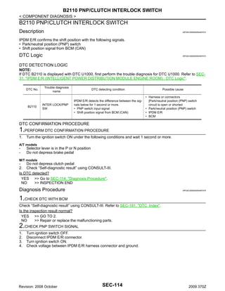
![B210F PNP/CLUTCH INTERLOCK SWITCH
< COMPONENT DIAGNOSIS >
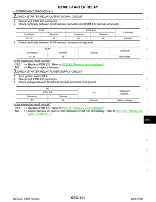
B210F PNP/CLUTCH INTERLOCK SWITCH
Description
INFOID:0000000004497569
IPDM E/R confirms the shift position with the following signals.
• Park/neutral position (PNP) switch
• Shift position signal from BCM (CAN)
DTC Logic
INFOID:0000000004497570
DTC DETECTION LOGIC
NOTE:
If DTC B210F is displayed with DTC U1000, first perform the trouble diagnosis for DTC U1000. Refer to SEC31, "IPDM E/R (INTELLIGENT POWER DISTRIBUTION MODULE ENGINE ROOM) : DTC Logic"
DTC No.
B210F
Trouble diagnosis name
INTER LOCK/PNP SW
ON
DTC detecting condition
Possible cause
IPDM E/R detects the difference between the signals below for 1 second or more.
• PNP switch input signal
• Shift position signal from BCM (CAN)
• Harness or connectors
[Park/neutral position (PNP) switch
circuit is open or shorted]
• Park/neutral position (PNP) switch
• IPDM E/R
• BCM
DTC CONFIRMATION PROCEDURE
1.PERFORM DTC CONFIRMATION PROCEDURE
1. Turn ignition switch ON under the following conditions and wait 1 second or more.
Selector lever is in the P or N position
Do not depress brake pedal
2. Check “Self-diagnostic result” using CONSULT-III.
Is DTC detected?
YES >> Go to SEC-112, "Diagnosis Procedure".
NO
>> INSPECTION END
Diagnosis Procedure
INFOID:0000000004497572
1.CHECK DTC WITH BCM
Check “Self-diagnostic result” using CONSULT-III. Refer to SEC-181, "DTC Index".
Is the inspection result normal?
YES >> GO TO 2.
NO
>> Repair or replace the malfunctioning parts.
2.CHECK PNP SWITCH SIGNAL
1.
2.
3.
4.
Turn ignition switch OFF.
Disconnect IPDM E/R connector.
Turn ignition switch ON.
Check voltage between IPDM E/R harness connector and ground.
(+)
IPDM E/R
Connector
(–)
Terminal
Selector lever
(A/T models)
E5
Voltage (V)
(Approx.)
Condition
30
Ground
Clutch pedal
(M/T models)
N or P position
Battery voltage
Other than above
0
Depressed
Battery voltage
Not depressed
0
Is the inspection result normal?
YES >> Replace IPDM E/R. Refer to PCS-33, "Removal and Installation".
Revision: 2008 October
SEC-112
2009 370Z](https://image.slidesharecdn.com/sec-140302061344-phpapp01/85/Sec-112-320.jpg)


![KEY SLOT
< COMPONENT DIAGNOSIS >
KEY SLOT
Description
INFOID:0000000004497580
When the Intelligent Key battery is discharged, it performs the NVIS (NATS) ID verification between the integrated transponder and BCM by inserting the Intelligent Key into the key slot, and then the engine can be
started.
Component Function Check
INFOID:0000000004497581
1.CHECK FUNCTION
1.
2.
Remove Intelligent Key battery from Intelligent Key.
Change power supply position when Intelligent Key insert into key slot and then press push-button ignition
switch.
Is the inspection result normal?
YES >> Key slot function is normal.
NO
>> Go to SEC-118, "Diagnosis Procedure".
Diagnosis Procedure
INFOID:0000000004497582
1.CHECK KEY SLOT POWER SUPPLY CIRCUIT
1.
2.
3.
Turn ignition switch OFF.
Disconnect key slot connector.
Check voltage between key slot harness connector and ground.
(+)
(–)
Voltage (V)
(Approx.)
Ground
Battery voltage
Key slot
Connector
Terminal
1
M22
5
Is the inspection result normal?
YES >> GO TO 2.
NO-1 >> Check 10 A fuse [No. 6 and 9 located in the fuse block (J/B)].
NO-2 >> Check harness for open or short between key slot and fuse.
2.CHECK KEY SLOT GROUND CIRCUIT
Check continuity between key slot harness connector and ground.
Key slot
Connector
Terminal
M22
Ground
7
Continuity
Existed
Is the inspection result normal?
YES >> Replace key slot. Refer to SEC-207, "Removal and Installation".
NO
>> Repair or replace harness.
Revision: 2008 October
SEC-118
2009 370Z](https://image.slidesharecdn.com/sec-140302061344-phpapp01/85/Sec-118-320.jpg)
![KEY SLOT INDICATOR
< COMPONENT DIAGNOSIS >
KEY SLOT INDICATOR
A
Description
INFOID:0000000004497583
Blinks when Intelligent Key insertion is required.
B
Component Function Check
INFOID:0000000004497584
1.CHECK FUNCTION
C
Check key slot illumination (“KEY SLOT ILLUMI”) Active Test mode.
D
Is the inspection result normal?
YES >> Key slot function is normal.
NO
>> Refer to SEC-119, "Diagnosis Procedure".
E
Diagnosis Procedure
INFOID:0000000004497585
1.CHECK KEY SLOT INDICATOR OUTPUT SIGNAL
F
Check voltage between key slot harness connector and ground.
Key slot
(+)
Connector
Condition
Key slot
illumination
Voltage (V)
(Approx.)
Insert Intelligent Key into
key slot
OFF
Remove Intelligent Key
from key slot
ON
0
G
Battery voltage
(–)
Terminal
M22
6
Ground
H
I
Is the inspection result normal?
YES >> GO TO 5.
NO
>> GO TO 2.
J
2.CHECK KEY SLOT POWER SUPPLY CIRCUIT
1.
2.
3.
Turn ignition switch OFF.
Disconnect key slot connector.
Check voltage between key slot harness connector and ground.
SEC
L
Key slot
(+)
Connector
(–)
Voltage (V)
(Approx.)
Terminal
M
1
M22
Ground
5
Battery voltage
N
Is the inspection result normal?
YES >> GO TO 3.
NO-1 >> Check 10 A fuse [No. 6 and 9 located in the fuse block (J/B)].
NO-2 >> Check harness for open or short between key slot and fuse.
O
3.CHECK KEY SLOT GROUND CIRCUIT
Check continuity between key slot harness connector and ground.
Key slot
Connector
Terminal
M22
Ground
7
P
Continuity
Existed
Is the inspection result normal?
YES >> GO TO 4.
Revision: 2008 October
SEC-119
2009 370Z](https://image.slidesharecdn.com/sec-140302061344-phpapp01/85/Sec-119-320.jpg)


![SECURITY INDICATOR LAMP
< COMPONENT DIAGNOSIS >
SECURITY INDICATOR LAMP
A
Description
INFOID:0000000004497590
• Security indicator lamp is located on combination meter.
• NVIS (Nissan Vehicle Immobilizer System) and vehicle security system conditions are indicated by blink or
illumination of security indicator lamp.
B
Component Function Check
C
INFOID:0000000004497591
1.CHECK FUNCTION
1.
2.
D
Perform “THEFT IND” in the “ACTIVE TEST” mode using CONSULT-III.
Check security indicator lamp operation.
Test item
Description
ON
THEFT IND
Security indicator lamp
OFF
E
Illuminates
Does not illuminate
F
Is the inspection result normal?
YES >> INSPECTION END
NO
>> Go to SEC-123, "Diagnosis Procedure".
G
Diagnosis Procedure
INFOID:0000000004497592
1.CHECK SECURITY INDICATOR LAMP POWER SUPPLY CIRCUIT
H
1.
2.
3.
I
Turn ignition switch OFF.
Disconnect combination meter connector.
Check voltage between combination meter harness connector and ground.
(+)
(–)
Voltage (V)
(Approx.)
Ground
Battery voltage
Combination meter
Connector
M53
1
J
Terminal
SEC
Is the inspection result normal?
YES >> GO TO 2.
NO-1 >> Check 10 A fuse [No. 11, located in the fuse block (J/B)].
NO-2 >> Check harness for open or short between combination meter and fuse.
L
2.CHECK SECURITY INDICATOR LAMP SIGNAL
1.
2.
3.
Connect combination meter connector.
Disconnect BCM connector.
Check voltage between BCM harness connector and ground.
M
N
(+)
(–)
Connector
141
Battery voltage
Terminal
M123
Voltage (V)
(Approx.)
Ground
BCM
O
Is the inspection result normal?
YES >> Replace BCM. Refer to BCS-84, "Removal and Installation".
NO
>> GO TO 3.
P
3.CHECK COMBINATION METER CIRCUIT
1.
2.
Disconnect combination meter connector.
Check continuity between combination meter harness connector and BCM harness connector.
Revision: 2008 October
SEC-123
2009 370Z](https://image.slidesharecdn.com/sec-140302061344-phpapp01/85/Sec-123-320.jpg)


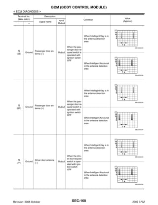
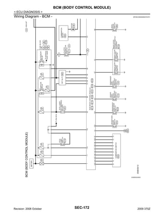
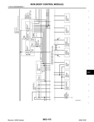
![BCM (BODY CONTROL MODULE)
< ECU DIAGNOSIS >
Terminal No.
(Wire color)
+
–
Description
Signal name
Condition
Input/
Output
Value
(Approx.)
A
B
When Intelligent Key is in
the antenna detection
area
77
(LG)
Ground
Driver door antenna
(+)
Output
C
When the driver door request
switch is operated with ignition switch
OFF
JMKIA0062GB
D
E
When Intelligent Key is not
in the antenna detection
area
F
JMKIA0063GB
G
During waiting
Ignition switch is pressed
while inserting the Intelligent Key into the key slot.
Just after pressing ignition
switch. Pointer of tester should
move.
Input/
Output
Ignition switch is pressed
while inserting the Intelligent Key into the key slot.
Just after pressing ignition
switch. Pointer of tester should
move.
H
During waiting
Output
Ignition switch
OFF or ACC
0V
I
ON
12 V
Ground
NATS antenna amp
(Built in key slot)
Input/
Output
81
(W)
Ground
NATS antenna amp
(Built in key slot)
82
(R)
Ground
Ignition relay [Fuse
block (J/B)] control
80
(GR)
J
During waiting
SEC
JMKIA0064GB
83
(GR)
Ground
Remote keyless entry
receiver communication
L
Input/
Output
M
When operating either button on the Intelligent Key
N
JMKIA0065GB
O
P
Revision: 2008 October
SEC-161
2009 370Z](https://image.slidesharecdn.com/sec-140302061344-phpapp01/85/Sec-161-320.jpg)
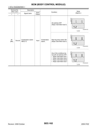


![BCM (BODY CONTROL MODULE)
< ECU DIAGNOSIS >
Priority
5
6
DTC
•
•
•
•
•
•
•
•
•
•
•
•
•
•
•
•
•
•
•
•
•
•
•
•
•
A
C1704: LOW PRESSURE FL
C1705: LOW PRESSURE FR
C1706: LOW PRESSURE RR
C1707: LOW PRESSURE RL
C1708: [NO DATA] FL
C1709: [NO DATA] FR
C1710: [NO DATA] RR
C1711: [NO DATA] RL
C1712: [CHECKSUM ERR] FL
C1713: [CHECKSUM ERR] FR
C1714: [CHECKSUM ERR] RR
C1715: [CHECKSUM ERR] RL
C1716: [PRESSDATA ERR] FL
C1717: [PRESSDATA ERR] FR
C1718: [PRESSDATA ERR] RR
C1719: [PRESSDATA ERR] RL
C1720: [CODE ERR] FL
C1721: [CODE ERR] FR
C1722: [CODE ERR] RR
C1723: [CODE ERR] RL
C1724: [BATT VOLT LOW] FL
C1725: [BATT VOLT LOW] FR
C1726: [BATT VOLT LOW] RR
C1727: [BATT VOLT LOW] RL
C1734: CONTROL UNIT
B
C
D
E
F
G
• B2621: INSIDE ANTENNA
• B2622: INSIDE ANTENNA
• B2623: INSIDE ANTENNA
H
DTC Index
INFOID:0000000004704754
I
NOTE:
The details of time display are as follows.
J
• CRNT: A malfunction is detected now.
• PAST: A malfunction was detected in the past.
IGN counter is displayed on Freeze Frame Data. For details of Freeze Frame Data, refer to BCS-17, "COMSEC
MON ITEM : CONSULT-III Function (BCM - COMMON ITEM)".
Fail-safe
Freeze Frame Data
•Vehicle Speed
•Odo/Trip Meter
•Vehicle condition
Intelligent Key
warning lamp ON
Tire pressure
monitor warning
lamp ON
Reference page
L
No DTC is detected.
further testing
may be required.
—
—
—
—
—
M
U1000: CAN COMM CIRCUIT
—
—
—
—
BCS-38
U1010: CONTROL UNIT (CAN)
—
—
—
—
BCS-39
U0415: VEHICLE SPEED SIG
—
—
—
—
BCS-40
B2013: ID DISCORD BCM-S/L
×
×
—
—
SEC-50
B2014: CHAIN OF S/L-BCM
×
×
—
—
SEC-51
B2190: NATS ANTENNA AMP
×
—
—
—
SEC-42
B2191: DIFFERENCE OF KEY
×
—
—
—
SEC-45
B2192: ID DISCORD BCM-ECM
×
—
—
—
SEC-46
B2193: CHAIN OF BCM-ECM
×
—
—
—
SEC-48
B2195: ANTI SCANNING
×
—
—
—
SEC-49
B2553: IGNITION RELAY
—
×
—
—
PCS-48
B2555: STOP LAMP
—
×
—
—
SEC-54
CONSULT display
Revision: 2008 October
SEC-181
2009 370Z
N
O
P](https://image.slidesharecdn.com/sec-140302061344-phpapp01/85/Sec-181-320.jpg)
![BCM (BODY CONTROL MODULE)
< ECU DIAGNOSIS >
Fail-safe
Freeze Frame Data
•Vehicle Speed
•Odo/Trip Meter
•Vehicle condition
Intelligent Key
warning lamp ON
Tire pressure
monitor warning
lamp ON
Reference page
B2556: PUSH-BTN IGN SW
—
×
×
—
SEC-56
B2557: VEHICLE SPEED
×
×
×
—
SEC-58
CONSULT display
B2560: STARTER CONT RELAY
×
×
×
—
SEC-59
B2562: LOW VOLTAGE
—
×
—
—
BCS-41
B2601: SHIFT POSITION
×
×
×
—
SEC-60
B2602: SHIFT POSITION
×
×
×
—
SEC-63
B2603: SHIFT POSI STATUS
×
×
×
—
SEC-66
B2604: PNP SW
×
×
×
—
SEC-69
B2605: PNP SW
×
×
×
—
SEC-71
B2606: S/L RELAY
×
×
×
—
SEC-73
B2607: S/L RELAY
×
×
×
—
SEC-74
B2608: STARTER RELAY
×
×
×
—
SEC-76
B2609: S/L STATUS
×
×
×
—
SEC-78
B260A: IGNITION RELAY
×
×
×
—
PCS-50
B260B: STEERING LOCK UNIT
—
×
×
—
SEC-82
B260C: STEERING LOCK UNIT
—
×
×
—
SEC-83
B260D: STEERING LOCK UNIT
—
×
×
—
SEC-84
B260F: ENG STATE SIG LOST
×
×
×
—
SEC-85
B2612: S/L STATUS
×
×
×
—
SEC-90
B2614: ACC RELAY CIRC
—
×
×
—
PCS-52
B2615: BLOWER RELAY CIRC
—
×
×
—
PCS-55
B2616: IGN RELAY CIRC
—
×
×
—
PCS-58
B2617: STARTER RELAY CIRC
×
×
×
—
SEC-94
B2618: BCM
×
×
×
—
PCS-61
B2619: BCM
×
×
×
—
SEC-96
B261A: PUSH-BTN IGN SW
—
×
×
—
PCS-62
—
SEC-97
B261E: VEHICLE TYPE
×
×
× (Turn ON for 15
seconds)
B2622: INSIDE ANTENNA
—
×
—
—
DLK-55
B2623: INSIDE ANTENNA
—
×
—
—
DLK-57
B26E8: CLUTCH SW
×
×
×
—
SEC-86
B26E9: S/L STATUS
×
×
× (Turn ON for 15
seconds)
—
SEC-88
B26EA: KEY REGISTRATION
—
×
× (Turn ON for 15
seconds)
—
SEC-89
C1704: LOW PRESSURE FL
—
—
—
×
C1705: LOW PRESSURE FR
—
—
—
×
C1706: LOW PRESSURE RR
—
—
—
×
C1707: LOW PRESSURE RL
—
—
—
×
C1708: [NO DATA] FL
—
—
—
×
C1709: [NO DATA] FR
—
—
—
×
C1710: [NO DATA] RR
—
—
—
×
C1711: [NO DATA] RL
—
—
—
×
Revision: 2008 October
SEC-182
WT-15
WT-17
2009 370Z](https://image.slidesharecdn.com/sec-140302061344-phpapp01/85/Sec-182-320.jpg)
![BCM (BODY CONTROL MODULE)
< ECU DIAGNOSIS >
Fail-safe
Freeze Frame Data
•Vehicle Speed
•Odo/Trip Meter
•Vehicle condition
Intelligent Key
warning lamp ON
Tire pressure
monitor warning
lamp ON
C1712: [CHECKSUM ERR] FL
—
—
—
×
C1713: [CHECKSUM ERR] FR
—
—
—
×
C1714: [CHECKSUM ERR] RR
—
—
—
×
C1715: [CHECKSUM ERR] RL
—
—
—
×
C1716: [PRESSDATA ERR] FL
—
—
—
×
C1717: [PRESSDATA ERR] FR
—
—
—
×
C1718: [PRESSDATA ERR] RR
—
—
—
×
C1719: [PRESSDATA ERR] RL
—
—
—
×
C1720: [CODE ERR] FL
—
—
—
×
C1721: [CODE ERR] FR
—
—
—
×
C1722: [CODE ERR] RR
—
—
—
×
C1723: [CODE ERR] RL
—
—
—
×
C1724: [BATT VOLT LOW] FL
—
—
—
×
C1725: [BATT VOLT LOW] FR
—
—
—
×
C1726: [BATT VOLT LOW] RR
—
—
—
×
C1727: [BATT VOLT LOW] RL
—
—
—
×
C1729: VHCL SPEED SIG ERR
—
—
—
×
WT-31
C1734: CONTROL UNIT
—
—
—
×
WT-33
CONSULT display
Reference page
A
B
WT-20
C
WT-23
D
E
WT-25
F
WT-28
G
H
I
J
SEC
L
M
N
O
P
Revision: 2008 October
SEC-183
2009 370Z](https://image.slidesharecdn.com/sec-140302061344-phpapp01/85/Sec-183-320.jpg)

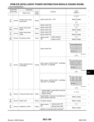
![IPDM E/R (INTELLIGENT POWER DISTRIBUTION MODULE ENGINE ROOM)
< ECU DIAGNOSIS >
Monitor Item
Condition
Value/Status
Ignition switch ON
At engine cranking
ST/INHI RLY
Off
INHI ON → ST ON
The status of starter relay or starter control relay cannot be recognized by the
battery voltage malfunction, etc. when the starter relay is ON and the starter
control relay is OFF
• Press the selector button with selector lever in P position
• Selector lever in any position other
than P
Ignition switch ON
DETENT SW
UNKWN
C
D
On
None of the conditions below are present
Off
• Open the driver door after the ignition switch is turned OFF (for a few seconds)
• Press the push-button ignition switch when the steering lock is activated
• Depress the clutch pedal when the steering lock is activated
On
Steering lock is activated
S/L STATE
OIL P SW
LOCK
Steering lock is deactivated
UNLOCK
UNKWN
Daytime running light system is not operated
HL WASHER REQ
THFT HRN REQ
HORN CHIRP
CRNRNG LMP REQ
G
Off
H
Daytime running light system is operated
On
Ignition switch OFF, ACC or engine running
Open
Ignition switch ON
I
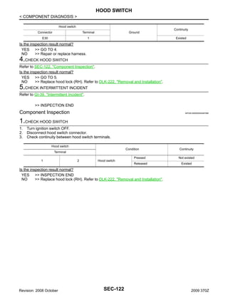
Close
Close the hood
Off
Open the hood
On
NOTE:
The item is indicated, but not monitored.
Off
Not operation
HOOD SW
E
F
[DTC: B210A] is detected
DTRL REQ
NOTE:
This item is monitored only on
the vehicle with the daytime
running light system.
B
Off
Release the selector button with selector lever in P position
NOTE:
Fixed On for M/T models
S/L RLY -REQ
A
Off
• Panic alarm is activated
• Horn is activated with VEHICLE SECURITY (THEFT WARNING) SYSTEM
On
Not operating
On
NOTE:
The item is indicated, but not monitored.
SEC
L
Off
Door locking with Intelligent Key (horn chirp mode)
J
Off
M
N
O
P
Revision: 2008 October
SEC-185
2009 370Z](https://image.slidesharecdn.com/sec-140302061344-phpapp01/85/Sec-185-320.jpg)


The document provides information on vehicle security systems for Nissan vehicles, including: 1. Sections cover the intelligent key system, Nissan vehicle immobilizer system (NATS), vehicle security system, component diagnosis, and symptom diagnosis. 2. Diagrams and descriptions are provided for each system, along with component locations, wiring diagrams, and diagnostic procedures. 3. The document also includes an ECU diagnosis section for the body control module and intelligent power distribution module, with reference values, wiring diagrams, fail-safe operation, and DTC indexes.