SlideShare a Scribd company logo
1 of 11
Download to read offline
Articles
https://doi.org/10.1038/s41560-020-00757-7
1
Department of Mechanical Engineering and Electrochemical Engine Center, The Pennsylvania State University, University Park, PA, USA. 2
EC Power,
State College, PA, USA. ✉e-mail: cxw31@psu.edu
T
he transportation sector accounts for 29% of US greenhouse
gas emissions, 59% of which come from light-duty vehicles
making personal trips1
. Powertrain electrification is a prom-
ising route for decarbonized transportation2
. In light of the Paris
Agreement, many countries have announced plans to phase out
internal combustion engine (ICE) vehicles and incentivize electric
vehicles (EVs). Driven by government policy and by rapid advances
in battery technology, global passenger EV sales soared from a few
thousand in 2010 to 2.1 million in 2019, and are projected to reach
8.5 million in 2025 and 54 million (58% of new car sales) in 20403
.
On this cusp of massive EV adoption, global automakers are plan-
ning an unprecedented level of investment (at least US$300 billion
in the next five years4
) to develop batteries and EVs.
The pursuit of higher battery energy density to eliminate range
anxiety has been the primary focus for EV battery development in
the past decade5–7
. Electric vehicle batteries have shifted from using
lithium iron phosphate (LFP) cathodes to ternary layered oxides
(nickel–manganese–cobalt (NMC) and nickel–cobalt–aluminium
(NCA)) due to the higher energy density of the latter8–10
. The global
market share of ternary batteries reached a record high of 90% in
201911
, and it was widely believed that future EV batteries would
converge on ternary cathodes increasingly rich in nickel, as a higher
nickel content renders a larger specific capacity and less demand for
expensive cobalt12,13
.
However, a critical issue of nickel rich cathodes is poor safety
due to the deterioration of thermal stability with increasing nickel
content14–17
. For instance, the onset temperature for self-sustained
exothermic reactions drops from 306°C for NMC111 (33% nickel)
to 260°C for NMC622 (60% nickel) and 232°C for NMC811 (80%
nickel)18
. Heat release, on the other hand, increases from 512.5Jg–1
for NMC111 to 721.4Jg–1
for NMC622 and 904.8Jg–1
for NMC811.
Furthermore, deformation of an NMC lattice at a high voltage
releases oxygen, posing a considerable risk of thermal runaway.
In comparison, LFP has a wide but flat exothermic reaction peak
at 250–360°C with a much smaller heat release of 147Jg–1
(ref. 19
),
and the strong P–O covalent bond prohibits oxygen release20
, thus
exhibiting intrinsic safety. Tests from Sandia National Laboratories21
showed that a ten-cell LFP module had only limited temperature
rise (peak temperature <79°C) on nail penetration. A similar test
on a seven-cell NMC module caused fires in all cells with a peak
temperature of 549°C. Wang and colleagues22
compared the fire
hazards of 80Ah LFP and 50Ah NMC cells by triggering thermal
runaway with a resistive heater and found that the NMC cell had
2.9 times the heat release rate and three times the toxic CO release
than the LFP cell. A recent report23
from China’s National Big Data
Alliance of New Energy Vehicles showed that 86% EV safety inci-
dents reported in China from May to July 2019 were on EVs pow-
ered by ternary batteries and only 7% were on LFP batteries.
Lithium iron phosphate cells have several distinctive advantages
over NMC/NCA counterparts for mass-market EVs. First, they are
intrinsically safer, which is the top priority of an EV. Second, the
use of LFP cells has brought the battery pack cost down24,25
to below
US$100 per kWh, a critical threshold for EVs to reach cost parity
with ICE cars. The cost of NMC/NCA packs, however, is around
US$156 per kWh as of 20193
and it will be challenging to reduce
this cost to US$100 per kWh any time soon. Third, LFP materials
are highly durable, rendering long battery life26
. Fourth, LFP has no
cobalt, a strategic metal whose sustainable supply is highly ques-
tionable13
. As such, LFP cells are promising for widespread adop-
tion in mass-market passenger EVs. The main barrier, however, is
the low energy density due to the limited specific capacity and dis-
charge voltage, which causes severe range anxiety. State-of-the-art
LFP cells have a specific energy of ~180Whkg–1
, whereas NMC
and NCA cells have reached >250Whkg–1
. Nonetheless, this gap in
energy density has been much narrowed at the pack level by recent
advances in cell-to-pack (CTP) technology. One example is the
blade battery recently unveiled by BYD27
, where single cells are as
long (600–2,500mm) as the pack and hence the cell-to-pack inte-
gration efficiency is 40% higher, resulting in similar specific energy
and even better energy density at the pack level of a LFP battery
compared to a ternary battery.
Although the much-improved CTP efficiency helps revisit LFP
batteries, mass-market passenger EVs truly free of range anxiety
still require key technological breakthroughs. Here we present
a thermally modulated LFP (TM-LFP) blade battery designed
to operate at an elevated temperature of around 60 °C. Working
Thermally modulated lithium iron phosphate
batteries for mass-market electric vehicles
Xiao-Guang Yang 1
, Teng Liu1
and Chao-Yang Wang 1,2 ✉
The pursuit of energy density has driven electric vehicle (EV) batteries from using lithium iron phosphate (LFP) cathodes in
early days to ternary layered oxides increasingly rich in nickel; however, it is impossible to forgo the LFP battery due to its
unsurpassed safety, as well as its low cost and cobalt-free nature. Here we demonstrate a thermally modulated LFP battery to
offer an adequate cruise range per charge that is extendable by 10min recharge in all climates, essentially guaranteeing EVs
that are free of range anxiety. Such a thermally modulated LFP battery designed to operate at a working temperature around
60°C in any ambient condition promises to be a well-rounded powertrain for mass-market EVs. Furthermore, we reveal that the
limited working time at the high temperature presents an opportunity to use graphite of low surface areas, thereby prospec-
tively prolonging the EV lifespan to greater than two million miles.
Nature Energy | VOL 6 | February 2021 | 176–185 | www.nature.com/natureenergy
176
Content courtesy of Springer Nature, terms of use apply. Rights reserved
Articles
Nature Energy
at 60 °C not only tackles the low-temperature issues of the LFP
chemistry but also considerably boosts kinetic and transport
properties, giving rise to 10 min fast charging and remarkable
power in all climates. We note that speedy, convenient replen-
ishment of on-board battery energy through 10 min recharge is
a cheaper and safer alternative than highly energy-dense batter-
ies or loading up sheer size batteries to eliminate range anxiety
for mass-market passenger EVs. Besides, we show that the ele-
vated operating temperature greatly simplifies battery thermal
management due to a 14-fold reduction in the need for battery
cooling, further enhancing the energy density of the LFP bat-
tery system beyond—and reducing cost below—that of the CTP
technology. Furthermore, the high operating temperature with a
limited exposure time makes it viable to utilize graphite with low
Brunauer–Emmett–Teller (BET) areas, which can prolong battery
life to greater than two million driving miles. On the whole, the
TM-LFP blade battery can fulfil all of the main criteria required
for EVs—that is, that they are low cost, ultra-safe, recharge quickly
(to be free of range anxiety), are weather independent and have a
long lifetime—and thus exhibit enormous potential for large-scale
adoption in the upcoming mass-market passenger EVs.
Cell-to-pack integration
Aside from cell-level energy density, another crucial factor affecting
the cruise range of an EV is the integration efficiency from cells to
a pack. A conventional battery pack consists of multiple modules,
each having numerous single cells (Fig. 1a). The mass and volume
of the cells are only part of that of the pack. We performed a survey
of the specific energy (gravimetric) and energy density (volumet-
ric) of commercial EV batteries at cell and pack levels, as presented
in Fig. 1c,d (see Supplementary Table 1 for details). Notably, most
EVs have a gravimetric cell-to-pack ratio (GCTP; that is, the ratio
of specific energy at the pack level to that at cell level) of around
0.55–0.65, meaning 35–45% of pack weight is taken by inactive
elements (battery management system, thermal management sys-
tem, metal cases, cabling, beams and so on). The volume efficiency
is more disappointing: the volumetric cell-to-pack ratio (VCTP)
of most EVs are below 0.4. To improve mass and space utilization,
several battery suppliers such as CATL and BYD have adopted
so-called CTP technology, which removes modules and directly
assembles cells into a pack. An example is the blade battery recently
unveiled by BYD27
. As schematically illustrated in Fig. 1b, a blade
battery pack builds on an array of wide (600–2,500mm) and short
cells having a similar width as the pack. All module-related parts
are removed, and the cells themselves can provide structural sup-
port so that heavy beams used in a conventional battery pack for
holding modules are saved as well. As such, the blade battery pack
in the newly unveiled BYD Han EV achieves an outstanding GCTP
of 0.85 and VCTP of 0.62, giving rise to similar specific density and
even better energy density at the pack level compared with EVs with
ternary batteries (Fig. 1c,d).
LFP blade battery
Here we evaluate the performance of LFP blade batteries under vari-
ous performance criteria required for EVs. Specifically, we compare
graphite-LFP cells in blade battery format (following the dimen-
sions from BYD27
) with conventional graphite-NMC622 cells in
prismatic format (VDA-BEV2 standard, the same dimensions as
the cells in BMW i3). Detailed cell design information is summa-
rized in Supplementary Table 2. The two types of cells are compared
in terms of energy and power densities, cruise range under both
city and highway driving scenarios, and fast-charging ability—all
under various ambient temperatures. Electrochemical–thermal
(ECT) models calibrated over a wide range of testing conditions
(Supplementary Figs. 1–4) are used to perform the comparison, as
detailed in the Methods. It should be noted that efficient operation
of blade batteries necessitates multitab or ‘tab everywhere' design
to minimize voltage loss along the foil length and ensure uniform
current distribution. Many such designs have been elaboratively
presented in the patent literature28–30
, resulting in very comparable
internal resistance of blade batteries to traditional short cells. This
is assumed in the present work without sketching the tab design in
Fig. 1b for simplicity. A detailed electron flow analysis along the cell
length can be found in Supplementary Note 1.
The most common approach to enhance the energy density of
a lithium ion cell is to increase the areal loading of the electrodes31
.
Figure 2 presents the specific energy and energy density of the LFP
and NMC622 cells under the fixed cell dimensions (Supplementary
Table 2). As expected, the LFP cells have lower specific energy and
energy density than the NMC622 cells (Fig. 2a,c), but this deficiency
can be compensated by the high CTP ratios of the blade battery pack
(Fig. 2b,d). At the loading of 4mAhcm2
, for instance, the pack-level
specific energy of the LFP blade battery reaches 156–175Whkg–1
at
a GCTP of ~0.8–0.9, compared with 145–171Whkg–1
for the con-
ventional NMC622 pack at a GCTP of ~0.55–0.65. The improve-
ment in volumetric energy density is more exciting. The LFP blade
battery pack at 4mAhcm–2
loading achieves an energy density of
286–333Whl–1
at a VCTP of ~0.6–0.7, which is much higher than
that of the conventional NMC622 pack (186–249Whl–1
at a VCTP
of ~0.3–0.4). It can be concluded that a blade-type LFP battery pack
can deliver specific energy comparable to and energy density even
higher than a state-of-the-art ternary battery pack (also compare
with Supplementary Table 1).
Peak battery power is vital for EVs, which represents the ability
for acceleration or regenerative braking. In the recently published
battery requirements for 2030 mass-market EVs32
, the European
Council for Automotive R&D (EUCAR) set a target of 1,440Wkg–1
for peak (10s) specific power and 3,000Wl–1
for peak power density
at the pack level in the state-of-charge (SOC) range of 10–100%.
Here we compare the power of the LFP blade cell and NMC622
VDA cell with the areal capacity of 3mAhcm–2
(see Supplementary
Table 2 for details; the discussion in the remainder of this work is
based on these two cells unless otherwise noted). The power den-
sity is assessed by a 10s discharge pulse at a constant voltage that
equals the lower cutoff voltage (2.4V for the LFP cell and 2.7V for
the NMC622 cell). Supplementary Figs. 5 and 6 present the spe-
cific power and power density of the two batteries at the cell and
pack levels under various temperatures and SOCs. Notably, a criti-
cal challenge to battery power is low temperature, as we can see that
both cells suffer an exponential drop in power with decreasing tem-
perature. As EVs need to operate in all weather conditions, boosting
battery power at low temperatures is vital for ensuring a pleasant
driving experience. On the other hand, we note that an increase in
temperature can enhance battery power substantially. If operating at
60°C, for instance, the specific power and power density of the LFP
blade battery can readily meet the EUCAR 2030 target even at 10%
SOC (Supplementary Figs. 5f and 6f).
The cruise range is the most crucial metric for an EV, which we
evaluate here for an EV powered by a 40kWh battery pack (com-
posed of either 62 of the 202Ah LFP blade cells or 69 of the 158Ah
NMC622 VDA cells in Supplementary Table 2). One example of
such an EV is the Nissan Leaf. We study two scenarios, city driv-
ing and highway driving, respectively, by following the Urban
Dynamometer Driving Schedule (UDDS) and US06 high accelera-
tion aggressive driving schedule defined by the US Environmental
Protection Agency (EPA)33
. The EPA-defined velocity profiles are
converted to battery power profiles (Supplementary Fig. 7) through
a vehicle dynamics model that is based on the specifications of
Nissan Leaf, as detailed in the Methods.
Figure 3a,b displays the voltage profiles of the LFP and
NMC622 cells under the above-mentioned driving schedules
at different temperatures, whereas Fig. 3c,d summarizes the
Nature Energy | VOL 6 | February 2021 | 176–185 | www.nature.com/natureenergy 177
Content courtesy of Springer Nature, terms of use apply. Rights reserved
Articles Nature Energy
corresponding driving range. Under UDDS protocol, the driv-
ing range with the two batteries is similar at warm temperatures
(decreasing moderately from 290 km at 60 °C to 270 km at 10 °C).
At freezing temperatures, however, the cruise range descends
rapidly, especially for the EV with the LFP blade battery whose
range falls to 158 km at −10 °C and 39 km at −20 °C, as compared
with 228 km at −10 °C and 157 km at −20 °C for the EV with
the NMC622 battery. The sharp reduction in the cruise range
of the LFP battery-powered EV can be attributed to the high
mass-transfer resistance in the thick LFP cathode. At the same
areal capacity of 3 mAh cm–2
, the thickness of the LFP cathode is
1.6 times that of the NMC622 cathode (Supplementary Table 2).
As electrolyte conductivity and diffusivity drop substantially at
low temperatures, the thick LFP cathode suffers much higher
ionic resistance (Supplementary Fig. 8a) and greater electrolyte
transport resistance (Supplementary Fig. 8b). Only half of the
LFP cathode in the vicinity of the separator can therefore be fully
lithiated at the end of the UDDS cycling at −10 °C (as shown
in Supplementary Fig. 8c) whereas the lithiation degree of the
NMC622 cathode is quite uniform.
The temperature effects on cruise range are more dramatic in
highway driving scenarios. Under the US06 protocol, as shown in
Fig. 3b,d, the driving range with the LFP battery falls to only 58%
of the driving range with the NMC622 battery at 0°C, and this ratio
drops further to 30% at −10°C. Such greater temperature effects are
attributed to the higher power demand for highway driving, which
induces a larger electrolyte concentration gradient in the thick LFP
cathode (Supplementary Fig. 8e). Accordingly, only one-fifth of the
LFP cathode can be fully lithiated at the end of the US06 cycling at
−10°C (Supplementary Fig. 8f).
Besides, we should note that regenerative braking, which accounts
for ~28% of the cruise range under UDDS protocol and ~20% under
US06 protocol, is typically prohibited at low temperatures as it can
induce lithium plating (Supplementary Fig. 9); thus, only the solid
bars in Fig. 3c,d should be considered as the driving range at <0°C,
making the cruise range even lower at freezing temperatures.
a
b
c d
Cell
Cell
Module Pack
Pack
200
180
160
140
120
100
160 180 200 220 240 260 280 300 350 400 450 500 550 600 650 700 750
300
250
200
150
100
50
0
Pack-level
specific
energy
(Wh
kg
–1
)
Pack-level
energy
density
(Wh
l
–1
)
Cell-level specific energy (Wh kg–1
) Cell-level energy density (Wh l–1
)
G
CTP
=
0.75
VCTP = 0.4
VCTP = 0.3
VCTP = 0.2
GCTP
=
0.65
GCTP
= 0.55
NIO ES8 (2018)
Hyundai Kona (2018)
Chevy Bolt (2018)
Tesla Model 3 LR (2018)
Hyundai Ioniq (2018)
Jaguar I-PACE (2019)
Renault ZE40 (2018)
BMW i3 (2018) BMW i3 (2019)
Renault ZE50 (2019)
Mercedes EQC (2019)
BYD Han (2020) (LFP blade battery)
Nissan Leaf (2018)
Audi E-Tron (2018)
Fig. 1 | Cell-to-pack technology. a,b, A schematic illustration of a conventional battery pack (a) and a blade battery pack (b). The conventional battery
pack uses cells to build a module and then assembles modules into a pack. A blade battery pack builds on wide and short cells and assembles them
directly into a pack, thereby having much higher mass and volume integration efficiencies than the conventional pack. c,d, A summary of the pack- and
cell-level gravimetric specific energy (c) and volumetric energy density (d) of the battery packs in state-of-the-art EVs. All parameters of the battery cells
and packs needed to calculate these data points, along with the corresponding references, are summarized in Supplementary Table 1.
Nature Energy | VOL 6 | February 2021 | 176–185 | www.nature.com/natureenergy
178
Content courtesy of Springer Nature, terms of use apply. Rights reserved
Articles
Nature Energy
Fast charging is widely recognized as the key to eliminating
range anxiety. The US Department of Energy has identified 10min
extreme fast charging as a crucial enabler of mainstream EV adop-
tion. The fundamental limitation of fast charging is lithium plat-
ing, which can drastically reduce battery life and even induce safety
hazards. Figure 4 displays the cell voltage and anode potential (at
the anode–separator interface) of the LFP and NMC622 cells dur-
ing charging at different C-rates and temperatures. A standard
constant-current–constant-voltage (CCCV) protocol is adopted
with an upper cutoff voltage of 3.65V for the LFP cell and 4.2V
for the NMC622 cell. As the two cells have the same anode design,
their anode potential profiles overlap in the initial constant current
charging step. Due to a lower upper voltage, the LFP cell enters the
constant voltage step earlier than the NMC622 cell, which leads to
a longer charging time (at the same C-rate) but prevents a further
drop of the anode potential. As such, the LFP cell is less susceptible
to lithium plating and therefore can be charged with a higher rate
than the NMC622 cell. For instance, the LFP cell can withstand 3C
charging at 25°C, whereas the NMC622 cell can only take 1.5C.
We note from Fig. 4 that temperature has a substantial impact on
the plating-free maximum charge rate (PF-MCR) of both cells (see
also Supplementary Fig. 10). The PF-MCR refers to the maximum
charge C-rate required for the anode potential to stay above 0V. We
can see that the PF-MCR at 0°C drops to 0.7C for the LFP cell and
0.4C for the NMC622 cell, prolonging the charging time (0–80%
SOC) to 80min for the LFP cell and 112min for the NMC622 cell
(Fig. 4d). On the other end, elevating cell temperature can boost
the fast-charging ability substantially. At 60°C, the PF-MCR rises to
4C for the NMC622 cell and to >6C for the LFP cell (Fig. 4f). The
LFP cell at 60°C has no lithium plating even when charging with an
aggressive protocol of CV at 3.65V throughout the process. Under
such a protocol, it takes only 9.4min to charge from 0 to 80% SOC.
It can be concluded that LFP blade batteries—with their high
CTP ratios—can deliver comparable specific energy and better
energy density at the pack level to NMC batteries; LFP cells are also
less susceptible to lithium plating and hence can be charged faster
than NMC cells. The most critical challenge to LFP batteries for
adoption in passenger EVs is the sharp reduction in cruise range
at freezing temperatures due to the high mass-transfer resistance
in the thick LFP cathodes. Besides, similar to NMC batteries, LFP
cells face the issues of much-reduced power and rechargeability at
low temperatures.
TM-LFP blade battery
We believe that a LFP battery of decent energy density at the pack
level, as elaborated above, coupled with a 10min fast rechargeability,
is an economical solution to mass-market passenger EVs. To this
end, we propose a TM-LFP blade battery designed to operate at an
elevated temperature of 60°C in any ambient condition. In practice,
this can be implemented by rapid heating before battery operation
(EV driving), which is feasible as long as the heating speed is fast.
For instance, we reported a self-heating lithium ion battery structure
with an embedded nickel foil as an internal heater34
, which achieves
a heating speed greater than 1°C per second, meaning that, even in
the extreme cold of −30°C, it takes only 90s for the battery to warm
up to 60°C before operation (driving). The added weight and cost
due to the introduction of nickel foils are negligibly small, estimated
to be 1.3% drop in specific energy and 0.47% increase in cost35,36
.
Furthermore, this cell structure has been demonstrated viable for
mass production and has already been utilized in real-world EVs37
.
a b
c d
280
240
200
160
120
700
600
500
400
300
1.0 1.5 2.0 2.5 3.0 3.5 4.0 1.0 1.5 2.0 2.5 3.0 3.5 4.0
1.0 1.5 2.0 2.5 3.0 3.5 4.0
1.0 1.5 2.0 2.5 3.0 3.5 4.0
350
300
250
200
150
100
200
180
160
140
120
100
80
Cathode areal capacity (mAh cm–2
)
Cathode areal capacity (mAh cm–2
) Cathode areal capacity (mAh cm–2
)
Cathode areal capacity (mAh cm–2
)
Cell-level
energy
density
(Wh
l
–1
)
Pack-level
energy
density
(Wh
l
–1
)
Cell-level
specific
energy
(Wh
kg
–1
)
Pack-level
specific
energy
(Wh
kg
–1
)
NMC622 VDA (VCTP ≈ 0.3–0.4)
NMC622 VDA (GCTP ≈ 0.55–0.65)
LFP blade (VCTP ≈ 0.6–0.7)
LFP blade (GCTP ≈ 0.8–0.9)
NMC622 VDA battery
LFP blade battery
Fig. 2 | Specific energy and energy density at cell and pack levels. a–d, The evolutions of the gravimetric-specific energy (a,b) and volumetric energy
density (c,d) of the LFP blade battery and NMC622 prismatic battery (VDA-BEV2 standard) at cell (a,c) and pack (b,d) level as a function of cathode areal
capacity. Both cells are under the fixed cell dimensions given in Supplementary Table 2. In all cases the anode and cathode porosities are fixed at 0.27, and
the negative-to-positive capacity ratio is fixed at 1.1.
Nature Energy | VOL 6 | February 2021 | 176–185 | www.nature.com/natureenergy 179
Content courtesy of Springer Nature, terms of use apply. Rights reserved
Articles Nature Energy
Operating at an elevated temperature is quite beneficial as the
performance of a lithium ion cell is fundamentally affected by the
rates of the following physicochemical processes: electrochemical
reactions at the surfaces of anode and cathode materials, lithium ion
conduction and diffusion in the electrolyte, and solid-state lithium
diffusion in anode and cathode particles. Key parameters that gov-
ern these processes all depend strongly on temperature, following
the Arrhenius law (Supplementary Fig. 11). For instance, LFP mate-
rials are known for having the issue of poor solid-state diffusivity
and have to be made into nanoparticles for use in lithium ion cells.
Elevating temperature from 20°C to 60°C can boost the solid-state
diffusivity of LFP by 60-fold (Supplementary Fig. 11) and thereby
can substantially mitigate the lithium diffusion resistance in LFP
particles. All of the aforementioned physicochemical processes
accelerate at the elevated temperature of 60°C, which can bring
numerous benefits to an EV, as detailed below.
First, operating a cell consistently at 60°C prevents the sharp
drop in cruise range at low ambient temperatures, which, as
idendified above, is the most critical barrier to LFP blade batter-
ies. Supplementary Fig. 12 shows the voltage profiles of a 40kWh
TM-LFP battery pack under the UDDS driving cycle at freezing
temperatures. The TM-LFP battery is preheated to 60°C before
driving, which consumes about 1.35% battery energy per 10°C tem-
perature rise according to the previous test results of cells with simi-
lar specific energy38
. This energy consumption is used to reset the
initial SOC of the TM-LFP battery for the UDDS cycle (for example,
it starts at 89.2% SOC in the case of −20°C ambient). Despite the
energy consumption for heating, we can see that the TM-LFP bat-
tery has much smaller voltage oscillations (that is, lower cell resis-
tance) and sustains much longer driving than regular LFP and NMC
cells that start the discharge at 100% SOC. Figure 5a summarizes the
driving range (calculated by integrating the UDDS velocity profile
in Supplementary Fig. 7a over the driving time) at different tem-
peratures. We can note that the TM-LFP battery enables a decent
cruise range at all ambient conditions. At warm temperatures, the
cruise range is about 290km (note that this range can be extended
to 400km if the battery is scaled up to 50–55kWh). At cold tem-
peratures (for instance, −20°C), despite the 10.8% battery energy
consumed for preheating, the TM-LFP battery still delivers a range
of 260km, which is far superior to the range with the regular LFP
blade battery (13km) and with the conventional NMC622 battery
(110km) at the −20°C ambient. The TM-LFP battery is thus able to
deliver adequate cruise range per charge in all climatic conditions.
Second, the TM-LFP battery exhibits extraordinary power at all
ambient temperatures. As shown in Supplementary Figs. 5 and 6, bat-
tery power drops exponentially with decreasing temperature, posing
a critical challenge to vehicle acceleration and regenerative braking
in cold weather. By operating consistently at 60°C, battery power, on
the one hand, becomes independent of ambient temperature (Fig. 5b),
whereas on the other it is further boosted by 2.4-fold (compared with
a b
c d
4.2
3.6
3.0
2.4
4.2
3.6
3.0
2.4
4.2
3.6
3.0
2.4
Voltage
(V)
Voltage
(V)
Voltage
(V)
4.2
3.6
3.0
2.4
4.2
3.6
3.0
2.4
4.2
3.6
3.0
2.4
Voltage
(V)
Voltage
(V)
Voltage
(V)
350
300
250
200
150
100
50
0
UDDS
driving
range
(km)
–20°C –10°C 0°C 10°C 25°C
Temperature (°C)
40°C 60°C
LFP blade battery NMC622 VDA battery
350
300
250
200
150
100
50
0
US06
driving
range
(km)
–20°C –10°C 0°C 10°C 25°C
Temperature (°C)
40°C 60°C
0 1 2 3 4 5
Driving time (h) Driving time (h)
6 7 8 9 10 0 0.5 1.0 1.5 2.0 2.5
25°C
0°C
–10°C
25°C
0°C
–10°C
LFP blade battery
NMC622 VDA battery
Fig. 3 | Cruise range under city and highway driving in different temperatures. a–d, A comparison of the driving behaviour of an EV (similar to a Nissan
Leaf) powered by a 40kWh battery pack composed of either the LFP blade cells or the NMC622 prismatic cells (VDA-BEV2 standard). The cell voltage
(a,b) and total driving range (c,d) at different temperatures are shown. Results in a and c are under the UDDS protocol, which represents a city-driving
scenario, whereas results in b and d are under the US06 protocol, representative of highway driving. The solid bars in c and d represent the driving range
without regenerative braking (replacing the positive values of power in Supplementary Fig. 7 with zero), and the sum of solid and dashed bars represents
the driving range with incorporation of regenerative braking. Note that regenerative braking at <0°C is typically prohibited due to the issue of lithium
plating (Supplementary Fig. 9).
Nature Energy | VOL 6 | February 2021 | 176–185 | www.nature.com/natureenergy
180
Content courtesy of Springer Nature, terms of use apply. Rights reserved
Articles
Nature Energy
the power at 20°C) owing to the enhanced electrochemical reactions
and transport processes. Even at 10% SOC, the specific power of the
TM-LFP battery still meets the target set forth by the EUCAR on peak
specific power for 2030 mass-market EVs (Fig. 5b).
Third, the TM-LFP battery enables weather-independent fast
charging in 10min (Fig. 5c). As noted above, the PF-MCR of a lith-
ium ion cell drops dramatically with the decrease of temperature
due to the issue of lithium plating (Supplementary Fig. 10), lead-
ing to an increase of charging time (0 to 80% SOC) from 30min at
20°C to 80min at 0°C for the regular LFP blade cell. By elevating
cell temperature to 60°C, the same LFP cell can withstand the most
aggressive protocol of CV charging at 3.65V throughout the process
and yields no lithium plating (Fig. 4f), cutting the charging time
to 9.4min. If using the more standard CCCV protocol at 6C rate,
it still only takes 10.1min (Fig. 4e). More importantly, such a fast
charging can be performed at all ambient temperatures using the
heated-charging approach presented in our recent works35,36
. Even if
the cell is initially at −30°C, the total time of charging to 80% SOC
would be only 10.9min (1.5min for heating from −30°C to 60°C
plus 9.4min for charging). The all-climate medium cruise range and
readily extendable through 10min fast charging, as offered by the
TM-LFP battery, can enable EVs ultimately free of range anxiety.
Also note that 6C charging of the 40kWh TM-LFP batteries needs
240kW chargers, which are readily available through Telsa V3
Supercharger Network or the 350kW fast-charge stations recently
installed by Electrify America. Most excitingly, the 40kWh TM-LFP
battery for a passenger EV free of range anxiety already exceeds cost
parity with ICE vehicles.
Fourth, the elevated temperature also greatly reduces battery
cooling need and thereby simplifies or even eliminates the battery
thermal management system (BTMS). The heat balance of a battery
cell can be mathematically expressed as:
I2
R ¼ h Tcell � Tamb
ð Þ ð1Þ
where the left-hand-side represents heat generation rate, with
I the current and R the cell internal resistance, whereas the
right-hand-side represents the heat dissipation rate, with h the heat
transfer coefficient and Tcell and Tamb the cell and ambient tempera-
tures, respectively. As shown in Fig. 5b, the 10s peak power (at 2.4V
constant voltage) of the LFP cell at 60°C is about double of that
at 25°C, meaning that the internal cell resistance at 60°C is about
half of that at 25°C. As such, the heat generation is reduced by
half as cell temperature rises from 25°C to 60°C. On the other
end, the driving force for heat dissipation (Tcell –Tamb) is enlarged to
35°C (Tcell at 60°C and Tamb at 25°C). Assuming that a conventional
BTMS can maintain cell temperature at 30°C (that is, 5°C tem-
perature difference for cooling) in regular operation, the strategy
of operating at 60°C boosts the term Tcell –Tamb by seven-fold.
Together with the halved heat generation, the value of h for a
TM-LFP battery is reduced to one-fourteenth of that for a regular
battery pack. In this context, passive air cooling, instead of active
liquid cooling, could suffice for a TM-LFP battery pack. Such a
simplified BTMS can further improve pack-level energy density
and reduce pack cost (for example, a current liquid cooling system
accounts for ~5% of battery pack weight39
and costs around US$250
for a 60kWh pack40
).
Million-mile EV Lifespan
In the past, it was believed that lithium-ion cells should avoid
operating at high temperatures due to the concern of acceler-
ated degradation. We recently revealed that cell aging driven by a
high temperature depends on the time of the cell at the high tem-
perature35
. For a TM-LFP battery, it is exposed to 60°C only dur-
ing operation, which is a small fraction of the lifetime of an EV.
According to the American Automobile Association41
, Americans
spend about 51min behind the wheel per day travelling for 31.5
miles (an average speed of 37mph); thus, the time of an EV on the
road, or of a TM-LFP battery at 60°C, is only 3.5% (51min out of
24h) of a vehicle’s lifespan. We should also note that LFP materials
are particularly suitable for high-temperature operation, given their
superior thermal stability. The primary aging mechanism in a LFP
cell is the growth of solid–electrolyte interphase (SEI) on graphite
a
b
c
d
e
f
4.4
4.0
3.6
3.2
2.8
0 10 20
Charging time (min) Charging time (min) Charging time (min)
30 40
0 10 20
Charging time (min)
30 40
Cell
voltage
(V)
4.4
4.0
3.6
3.2
2.8
Cell
voltage
(V)
4.4
4.0
3.6
3.2
2.8
Cell
voltage
(V)
25°C
Li plating Li plating Li plating
0°C 60°C
LFP, 1.5C
LFP, 3C
LFP, 0.4C
LFP, 0.7C
NMC622, 1.5C
NMC622, 3C
NMC622, 0.4C
NMC622, 0.7C
LFP, 4C
LFP, 6C
LFP, CV@3.65V
NMC622, 4C
NMC622, 6C
0 30 60 90 120 150
Charging time (min)
0 30 60 90 120 150
0 4 8 12 16
Charging time (min)
0 4 8 12 16
0.3
0.2
0.1
–0.1
0
Anode
potential
(V)
0.3
0.2
0.1
–0.1
0
Anode
potential
(V)
0.3
0.2
0.1
–0.1
0
Anode
potential
(V)
Fig. 4 | Fast-charging capability at different temperatures. a–f, The evolutions of cell voltage (a,c,e) and anode potential (b,d,f) (at the anode–separator
interface) during charging of the blade-type graphite-LFP cell and the prismatic-type (VDA-BEV2 standard) graphite-NMC622 cell at different charge
rates and temperatures: 25°C (a,b), 0°C (c,d), 60°C (e,f). The cells are initially at 0% SOC, and the solid circles denote the time of reaching 80% SOC.
The LFP and NMC622 cells follow the design information in Supplementary Table 2.
Nature Energy | VOL 6 | February 2021 | 176–185 | www.nature.com/natureenergy 181
Content courtesy of Springer Nature, terms of use apply. Rights reserved
Articles Nature Energy
surfaces, which is mainly a function of temperature, SOC and time.
Supplementary Fig. 13 presents the calendar-life data of a widely
utilized commercial graphite-LFP cell from Sony42
. Even at 100%
SOC, the fastest SEI growth scenario, the cell at 60°C still has a life-
time (at 20% capacity loss) of 660 days. For a TM-LFP battery, a
total of 660 day operating time at 60°C represents a lifespan of 51
years and 586,080 miles (based on 51min driving time a day at an
average speed of 37mph).
As the SEI growth rate is proportional to the BET area of graphite
(equation (9))43
, the lifetime of a TM-LFP battery can be further
enhanced by using graphite with low BET areas (for example, larger
particles). In the past, low-BET-area graphite was not typically used
in EV batteries, as a reduced surface area increases charge transfer
resistance and larger particles lead to higher diffusion resistance.
Elevating cell temperature from 20°C to 60°C can boost graph-
ite reaction kinetics by 12-fold and graphite solid-state diffusivity
5.6-fold (Supplementary Fig. 11), effectively mitigating the adverse
effects due to a reduced BET area. As shown in Supplementary
Fig. 14, the increase of graphite particle size has minimal impacts
on the cruise range of a TM-LFP battery-powered EV under either
the UDDS or US06 protocol (Supplementary Fig. 14a), and a cell
with two times the graphite radius at 60°C even has better peak
power than the baseline cell at 20°C (Supplementary Fig. 14b).
Regarding fast charging, a cell with 1.5 times the graphite radius can
still be safely (without lithium plating) charged with the 6C current
and 3.65V cutoff voltage of the CCCV protocol at 60°C and takes
10.3min to charge from 0 to 80% SOC (Supplementary Fig. 14c,d),
and the cell with two times the graphite radius can be charged to
80% SOC in 11.8min with 6C rate and a lower cutoff voltage of
3.6V (to prevent lithium plating). These results demonstrate that the
elevated temperature of 60°C makes the performance of a TM-LFP
cell insensitive to graphite particle radius. On the other hand, the
particle size of graphite has a considerable impact on SEI growth
at 60°C. As shown in Fig. 5d, the calendar life at 20% capacity loss
of the above-mentioned graphite-LFP cell at 60°C and 100% SOC
can be prolonged to 1,368 days with a 1.5 times the graphite radius,
which, based on an average speed of 37mph, corresponds to greater
than 1.2 million driving miles for a TM-LFP battery-powered EV.
If the graphite radius is doubled, the lifetime at 60°C and 100%
SOC soars further to 2,315 days, corresponding to greater than
two million miles.
It is understood that battery cycling may cause additional deg-
radation due to lithium insertion and extraction (for example,
active material particle cracking). Dahn et al44,45
. showed that the
cycling-induced loss is however lessened at high temperatures
and that the capacity loss of cells under cycling and storage almost
overlap in the time domain at >40°C. Schimpe et al46
compared
the capacity loss of the Sony/Murata LFP cells during cycling
and storage and found that the pure cycling-induced loss follows
a square-root dependency on an equivalent full cycle (EFC). By
extrapolating their data (at 55°C) and assuming 300 miles per EFC,
we estimate a ~10% additional capacity loss after two million miles
(~6,700 EFCs). Even when adding this cycling-induced loss, the
TM-LFP battery with double the graphite radius is still projected to
a
b
c
d
350
300
250
200
150
100
50
0
–20°C –10°C 0°C 10°C
Ambient temperature (°C) Ambient temperature (°C)
Ambient temperature (°C)
25°C 40°C 60°C
UDDS
driving
range
(km)
LFP blade
TM-LFP blade
NMC622 VDA
2,000
1,600
1,200
800
400
0
–20 –10 0 10 20 30 40 50 60
Pack-level
specific
power
(W
kg
–1
)
TM-LFP blade battery (GCTP ≈ 0.9)
LFP blade battery (GCTP ≈ 0.85)
NMC622 VDA battery (GCTP ≈ 0.65)
100
90
80
70
Capacity
retention
(%)
0 400 800 1,200 1,600 2,000 2,400
Days
Storage at 60°C, 100% SOC
Sony/Murata commercial cell
ECT model, Baseline
ECT model, 1.5x graphite radius
ECT model, 2.0x graphite radius
120
100
80
60
40
20
0
0 10 20 30 40 50 60
NMC622 VDA battery
LFP blade battery
TM-LFP blade battery
Charge
time
to
80%
SOC
(min)
EUCAR 2030 target
Fig. 5 | All-climate cruise range, remarkable power and 10min fast charging with a TM-LFP blade battery. a–c, Comparisons of the TM-LFP blade battery
with the regular LFP blade battery and the conventional NMC622 prismatic battery (VDA-BEV2 standard) in terms of: cruise range under the UDDS at
different ambient temperatures for an EV with a 40kWh battery composed of either of the three types of cells (a); pack-level specific power at 10% SOC
(b); and the minimum time to charge from 0 to 80% SOC without lithium plating (c). The TM-LFP blade battery is preheated from ambient temperature to
60°C before an operation, which consumes 1.35% SOC per 10°C temperature rise (used for calculating the initial SOC in Fig. 5a; for instance, the TM-LFP
battery at 25°C starts at 95.3% SOC). The heating speed is 1°C per second, and the heating time is included in the charging time of the TM-LFP battery
shown in Fig. 5c. d, The calendar life of a graphite-LFP battery with different graphite particle sizes at 60°C and 100% SOC. The solid symbols represent the
experimental data from the literature on a commercial cell, and the lines are results predicted by a calibrated ECT aging model (see Supplementary Fig. 13).
Nature Energy | VOL 6 | February 2021 | 176–185 | www.nature.com/natureenergy
182
Content courtesy of Springer Nature, terms of use apply. Rights reserved
Articles
Nature Energy
retain ~70% capacity after two million miles, which is greater than
16 times the warranty on many commercial EV batteries (for exam-
ple, Tesla Model 3, 70% capacity for eight years or 120,000 miles).
The TM-LFP battery therefore offers an opportunity to use graph-
ite of low BET areas, enabling high performance and long lifetime
simultaneously.
Conclusions
Figure 6 summarizes the performance metrics of the above three
batteries: the NMC622 VDA battery, the regular LFP blade bat-
tery and the TM-LFP blade battery. With the improved CTP
ratios, the LFP blade battery delivers comparable specific energy
and better energy density at the pack level to the conventional
NMC battery, offering a medium cruise range for passenger EVs
at warm temperatures; LFP cells can also be charged faster than
NMC cells due to a lower cutoff voltage, which helps prevent
lithium plating. The primary challenge to LFP blade batteries for
use in passenger EVs is the sharp reduction in cruise range at
low temperatures, along with a drop in peak power and PF-MCR.
Designed for operating at 60 °C in any ambient conditions, the
TM-LFP battery not only tackles the issues at low temperatures
but further boosts battery power and fast charging ability, lead-
ing to adequate cruise range coupled with 10 min fast recharge in
all weather conditions. The elevated temperature also simplifies
BTMS due to a 14-fold reduction in battery cooling need, which
further enhances CTP efficiency and reduces cost. Moreover,
the elevated operating temperature with a limited exposure time
presents a way to achieving high performance and long lifetime
simultaneously and makes it viable for using graphite of low BET
areas, which can prospectively prolong the lifetime of an EV to
over two million miles.
The world is currently at the inflection point of massive EV
penetration. The TM-LFP blade battery presented in this work
offers adequate cruise range per charge that is readily extendable
through a 10 min recharge, and does so in all climates. We believe
that such a TM-LFP battery is a viable alternative to energy-dense
NMC/NCA batteries or carrying big batteries (for example,
100 kWh) on board to free EVs from range anxiety. Furthermore,
the LFP battery enjoys unsurpassed advantages in safety, cost and
containing no cobalt or nickel. Figure 6 shows that the TM-LFP
battery can fulfil all major criteria required for EVs, presenting
enormous potential for large-scale adoption in mass-market pas-
senger EVs.
Methods
ECT model. The physics-based ECT model solves the following governing
equations:
Charge conservation in solid electrodes: ∇  σs∇ϕs
 
¼ jtot ð2Þ
where ϕs is the solid-phase potential, σs is the electronic conductivity of the solid
and jtot is the total volumetric current density.
Charge conservation in electrolyte: ∇  κe∇ϕe
 
þ ∇  κD∇ ln ce
ð Þ ¼ �jtot ð3Þ
50
100
150
200
100
200
300
400
300
600
900
1,200
300
600
900
1,200
120
80
40
0
120
80
40
0
400
800
1,200
1,600
7
6
5
4
3
175
150
125
100
75
Low temperature charge time (min)
(0°C, 0–80% SOC)
Low temperature peak power (Wh kg–1
)
(Pack level,10%SOC, –20°C)
Peak power (Wh kg–1
)
(Pack level,10%SOC, 25°C)
Energy density (Wh l–1
)
(Pack level)
Specific energy (Wh kg–1
) (Pack level)
Charge time (min)
(25°C, 0–80% SOC)
Calendar life (days)
(60°C, 100% SOC)
Safety
(EUCAR level)
Cost (US$ per kWh)
NMC622 VDA battery Regular LFP blade battery TM-LFP blade battery
Fig. 6 | TM LFP blade battery fulfils all main criteria required for mass-market EVs. Comparisons of the TM-LFP blade battery (red), regular LFP
blade battery (blue) and NMC622 prismatic battery (grey, VDA-BEV2 standard) under various performance criteria. The cells have an areal capacity
of 3 mAh cm–2
(Supplementary Table 2). The specific energy and power are at the pack level, assuming a GCTP of 0.65 for the NMC622 battery, 0.85
for the regular LFP blade battery and 0.9 for the TM-LFP blade battery (with a simplified thermal management system). The temperatures in this
figure refer to ambient temperatures. The TM-LFP battery refers to the cell with 1.5 times the graphite radius. The data points are from Fig. 2b for
specific energy, Fig. 2d for energy density, Supplementary Figs. 5f and 14b for peak power, Fig. 4 and Supplementary Fig. 14d for charge time, and
Fig. 5d for calendar life. The safety data are based on the EUCAR safety levels defined in ref. 32
. The battery cost are based on ref. 3
for an NMC battery
and ref. 24
for a LFP battery, and the TM-LFP battery can further reduce cost by simplifying battery thermal management system (~US$250 for a
60 kWh battery pack40
).
Nature Energy | VOL 6 | February 2021 | 176–185 | www.nature.com/natureenergy 183
Content courtesy of Springer Nature, terms of use apply. Rights reserved
Articles Nature Energy
where ϕe is the electrolyte-phase potential, κe and κD are the ionic conductivity
and diffusional ionic conductivity of the electrolyte, respectively, and ce is the
concentration of the electrolyte.
Mass conservation in electrolyte:
∂ εce
ð Þ
∂t
¼ ∇  De∇ce
ð Þ þ
1 � tþ
F
jtot ð4Þ
where ε is electrode porosity, t is time, De is the diffusivity of the electrolyte, t+ the
transference number and F is the Faraday constant.
Mass conservation in active materials:
∂cs
∂t
¼
1
r2
∂
∂r
Dsr2 ∂cs
∂r
 
ð5Þ
where cs and Ds are the lithium concentration and diffusivity in solid active
materials, respectively, and r is the particle radius.
Energy conservation: mCp
dT
dt
¼ Q þ hA T � Tamb
ð Þ ð6Þ
where T is cell temperature, m, Cp and A are cell mass, thermal capacity and surface
area, respectively, Q is heat generation rate, h is heat transfer coefficient, and Tamb is
ambient temperature.
The total volumetric current density, jtot, is the sum of the current density of
the main and side reactions. The main reaction here refers to lithium intercalation/
deintercalation, whose current density is calculated by the Butler–Volmer equation:
jm ¼ ai0;m exp
αaF
RT
ηm
 
� exp �
αcF
RT
ηm
 
 
ð7Þ
where i0,m and ηm are the exchange current density and overpotential of the main
reactions, respectively, αa and αc are the anodic and cathodic charge transfer
coefficients, and a is the specific surface area (BET area), which depends on the
volume fraction (εAM) and r of the active materials (AM):
a ¼
3εAM
r
ð8Þ
Solid–electrolyte interphase growth in the anode is considered as a side
reaction in this model to account for cell aging, whose current density is calculated
via the Tafel equation:
jSEI ¼ �aFk0;SEIcs
EC exp �
αc;SEIF
RT
ηSEI
 
ð9Þ
where k0,SEI is a kinetic rate constant and cs
EC
I
is the concentration of ethylene
carbonate (EC) on the surface of graphite, which is calculated based on the mass
conservation of EC:
�DEC
cs
EC � cbulk
EC
δSEI
¼ �
jSEI
F
ð10Þ
where DEC and cbulk
EC
I
are the diffusivity and bulk concentration of EC, respectively,
and δSEI is the SEI layer thickness.
Model validation
The above model is used to predict the performance of two types
of cells: a graphite-LFP cell and a graphite-NMC622 cell. We per-
formed a set of validations to calibrate the model parameters to
reasonably predict the characteristics of LFP and NMC622 cells.
The model for the graphite-NMC622 cell was validated against the
experimental data of a 10Ah pouch cell presented in refs. 47,48
, and
the model for the graphite-LFP cell was validated against the data
of a commercial 20Ah cell given in refs. 49,50
. The model validation
includes comparing with the experimental data of (1) charge and
discharge with various C-rates at 25°C and (2) charge and discharge
with 1C rate at various ambient temperatures. As can be seen from
Supplementary Figs. 1–4, both the cell voltage and temperature
can be predicted reasonably well under all these conditions, dem-
onstrating that the models can well capture the electrochemical
and thermal behaviours of LFP and NMC622 cells. The calibrated
models are then used to predict the performance of the blade-type
graphite-LFP cell and the VDA-type graphite-NMC622 cell, follow-
ing the cell design information in Supplementary Table 2.
The aging model is validated against the calendar aging data of
a commercial graphite-LFP cell from Sony/Murata presented in ref.
42
. We can see from Supplementary Fig. 13 that the model well pre-
dicts the calendar life of the cell at various temperatures and SOCs.
The calibrated model was then applied to predict the calendar life of
cells with low BET-area graphite (Fig. 5d), changing only the radius
of graphite particles.
Vehicle dynamics model
The vehicle dynamics model in ref. 51
is adopted to convert the US
EPA-defined velocity profiles for the UDDS and US06 driving cycles
to battery power profiles (Supplementary Fig. 7). Here we used the
specifications of Nissan Leaf (with 40kWh battery) to calculate the
power at the wheels:
PwheelsðtÞ ¼ mV
dvðtÞ
dt þ mVg cosðθÞ Cr
1;000 ðc1vðtÞ þ c2Þ

þ 1
2 ρairAf CDv2
ðtÞ þ mVg sinðθÞ

vðtÞ
ð11Þ
where mv is the vehicle mass (1,995kg), v(t) is the velocity (in metres
per second), g is the gravity of Earth (9.8ms–2
), θ is climbing angle
(assumed to be 0), Cr =1.75, c1 =0.0328 and c2 =4.575 are rolling
resistance parameters, ρair is the air density (1.225kgm–3
), Af is the
front area of the vehicle (2.7356m2
) and CD is the aerodynamic drag
coefficient (0.28).
The power of the battery pack in traction and regenerative brak-
ing modes is then calculated as:
Traction mode: Pbatt ¼ Pwheels= ηT ηmd
ð Þ ð12aÞ
Regenerative braking mode: Pbatt ¼ Pwheelsηrb ð12bÞ
where ηT is the transmission efficiency (92%), ηmd is the efficiency
of the electric motor (91%) and ηrb is the efficiency of regenera-
tive braking (82%). The calculated battery pack power is divided
by the number of cells in the pack to calculate the power of single
cells, which is then implemented in the above ECT models. In this
work we study a 40kWh battery pack, which consists of either 62
of the 202Ah LFP blade cells or 69 of the 158Ah NMC622 VDA
cells in Supplementary Table 2. The driving cycle power profiles are
repeated until the single-cell voltage reaches the cutoff value (2.4V
for the LFP cell and 2.7V for the NMC622 cell). The driving range
shown in Figs. 3 and 5 are calculated by integrating the velocity pro-
files over time.
Data availability
All relevant data are included in the paper and its Supplementary Information.
Source data are provided with this paper.
Code availability
The case files for the cell performance and degradation simulations on
Autolion-1D v7.0 are publicly available at https://github.com/ECECPSU/TMLFP
Received: 3 August 2020; Accepted: 1 December 2020;
Published online: 18 January 2021
References
1. Fast Facts: US Transportation Sector Greenhouse Gas Emissions (1990–2018)
(US EPA, 2019); https://nepis.epa.gov/Exe/ZyPDF.cgi?Dockey=P100ZK4P.pdf
2. Needell, Z. A., McNerney, J., Chang, M. T.  Trancik, J. E. Potential for
widespread electrification of personal vehicle travel in the United States.
Nat. Energy 1, 16112 (2016).
3. Electric Vehicle Outlook 2020 (BloombergNEF, 2020); https://about.bnef.com/
electric-vehicle-outlook/
4. Lienert, P.  Chan, C. Global automakers investing at least $300 billion on
batteries and EVs. Reuters (2019); https://graphics.reuters.com/AUTOS-
INVESTMENT-ELECTRIC/010081ZB3HD/index.html
5. Whittingham, M. S. Lithium batteries and cathode materials. Chem. Rev. 104,
4271–4302 (2004).
6. Nitta, N., Wu, F., Lee, J. T.  Yushin, G. Li-ion battery materials: present and
future. Mate. Today 18, 252–264 (2015).
Nature Energy | VOL 6 | February 2021 | 176–185 | www.nature.com/natureenergy
184
Content courtesy of Springer Nature, terms of use apply. Rights reserved
Articles
Nature Energy
7. Schmuch, R., Wagner, R., Hörpel, G., Placke, T.  Winter, M. Performance
and cost of materials for lithium-based rechargeable automotive batteries.
Nat. Energy 3, 267–278 (2018).
8. Li, M., Lu, J., Chen, Z.  Amine, K. 30 Years of lithium-ion batteries.
Adv. Mater. 30, 1800561 (2018).
9. Ding, Y., Cano, Z. P., Yu, A., Lu, J.  Chen, Z. Automotive Li-ion
batteries: current status and future perspectives. Electrochem. Energy Rev. 2,
1–28 (2019).
10. Andre, D. et al. Future generations of cathode materials: an automotive
industry perspective. J. Mater. Chem. A 3, 6709–6732 (2015).
11. LFP market share drops in 2019 but expect a comeback with cell-to-pack.
Adamas Intelligence (4 March 2020); https://www.adamasintel.com/lfp-market-
2019-cell-to-pack-comeback/
12. Sun, Y.-K. et al. High-energy cathode material for long-life and safe lithium
batteries. Nat. Mater. 8, 320–324 (2009).
13. Olivetti, E. A., Ceder, G., Gaustad, G. G.  Fu, X. Lithium-ion battery supply
chain considerations: analysis of potential bottlenecks in critical metals. Joule
1, 229–243 (2017).
14. Manthiram, A., Knight, J. C., Myung, S.-T., Oh, S.-M.  Sun, Y.-K.
Nickel-rich and lithium-rich layered oxide cathodes: progress and
perspectives. Adv. Energy Mater. 6, 1501010 (2016).
15. Manthiram, A., Song, B.  Li, W. A perspective on nickel-rich layered oxide
cathodes for lithium-ion batteries. Energy Storage Mater. 6, 125–139 (2017).
16. Xiong, R., Ma, S., Li, H., Sun, F.  Li, J. Toward a safer battery management
system: a critical review on diagnosis and prognosis of battery short circuit.
iScience 23, 101010 (2020).
17. Feng, X., Ren, D., He, X.  Ouyang, M. Mitigating thermal runaway of
lithium-ion batteries. Joule 4, 743–770 (2020).
18. Noh, H.-J., Youn, S., Yoon, C. S.  Sun, Y.-K. Comparison of the structural
and electrochemical properties of layered Li[NixCoyMnz]O2 (x = 1/3, 0.5, 0.6,
0.7, 0.8 and 0.85) cathode material for lithium-ion batteries. J. Power Sources
233, 121–130 (2013).
19. Yamada, A., Chung, S. C.  Hinokuma, K. Optimized LiFePO4 for lithium
battery cathodes. J. Electrochem. Soc. 148, A224 (2001).
20. Zaghib, K. et al. Enhanced thermal safety and high power performance of
carbon-coated LiFePO4 olivine cathode for Li-ion batteries. J. Power Sources
219, 36–44 (2012).
21. Lamb, J., Torres-Castro, L., Stanley, J., Grosso, C.  Gray, L. S. Evaluation of
Multi-cell Failure Propagation SAND-2020-2802 (Sandia National
Laboratories, 2020); https://doi.org/10.2172/1605985
22. Wang, Z., Zhu, K., Hu, J.  Wang, J. Study on the fire risk associated with a
failure of large-scale commercial LiFePO4/graphite and LiNixCoyMn1-x-yO2/
graphite batteries. Energy Sci. Eng. 7, 411–419 (2019).
23. New Energy Vehicles Safety Monitoring Results Report (National Big Data
Alliance of New Energy Vehicles, 2019).
24. Morris, J. Tesla’s shift to cobalt-free batteries is its most important move yet.
Forbes (11 July 2020); https://www.forbes.com/sites/jamesmorris/2020/07/11/
teslas-shift-to-cobalt-free-batteries-is-its-most-important-move-yet/
25. Mullaney, T. Tesla and the science behind the next-generation, lower-cost,
‘million-mile’ electric-car battery. CNBC TECH TRENDS (30 June 2020);
https://www.cnbc.com/2020/06/30/tesla-and-the-science-of-low-cost-next-
gen-ev-million-mile-battery.html
26. Takahashi, M., Ohtsuka, H., Akuto, K.  Sakurai, Y. Confirmation of
long-term cyclability and high thermal stability of LiFePO4 in prismatic
lithium-ion cells. J. Electrochem. Soc. 152, A899 (2005).
27. Wang, C., He, L., Sun, H., Lu, P.  Zhu, Y. Battery pack, vehicle and energy
storage device. China Patent CN110165118B (2019).
28. He, K., Jiang, W., Wang, X.  Wen, A. Single battery, power battery pack and
vehicle. China Patent CN110364675A (2019).
29. Jiang, L., Yang, K., Zhu, Y.  Zhu, J. Electric connector and battery
comprising the same. United States Patent US20170346065A1 (2017).
30. Kwon, M., Choi, J., Kwon, K., Do, E.  Lee, Y. Complex electrode assembly
including plurality of electrode assemblies and electrochemical device
comprising the complex electrode assembly. United States Patent
US20200020922A1 (2020).
31. Gallagher, K. G. et al. Optimizing areal capacities through understanding the
limitations of lithium-ion electrodes. J. Electrochem. Soc. 163, A138–A149
(2015).
32. Battery Requirements for Future Automotive Applications (EUCAR, 2019);
https://eucar.be/wp-content/uploads/2019/08/20190710-EG-BEV-FCEV-Batter
y-requirements-FINAL.pdf
33. Dynamometer Drive Schedules. United States Environmental Protection
Agency https://www.epa.gov/vehicle-and-fuel-emissions-testing/
dynamometer-drive-schedules
34. Wang, C. Y. et al. Lithium-ion battery structure that self-heats at low
temperatures. Nature 529, 515–518 (2016).
35. Yang, X. G. et al. Asymmetric temperature modulation for extreme fast
charging of lithium-ion batteries. Joule 3, 3002–3019 (2019).
36. Yang, X. G., Zhang, G., Ge, S.  Wang, C. Y. Fast charging of
lithium-ion batteries at all temperatures. Proc. Natl Acad. Sci. USA 115,
7266–7271 (2018).
37. Yang, X. et al. All-climate battery technology for electric vehicles: inching
closer to the mainstream adoption of automated driving. IEEE Electrific. Mag.
7, 12–21 (2019).
38. Zhang, G. et al. Rapid self-heating and internal temperature sensing
of lithium-ion batteries at low temperatures. Electrochim. Acta 218,
149–155 (2016).
39. Nelson, P. A., Ahmed, S., Gallagher, K. G.  Dees, D. W. Modeling the
Performance and Cost of Lithium-Ion Batteries for Electric-Drive Vehicles 3rd
edn ANL/CSE-19/2 (Argonne National Laboratory, 2020).
40. Lutsey, N.  Nicholas, M. Update on Electric Vehicle Costs in the
United States Through 2030 1–12 (International Council on Clean
Transportation, 2019).
41. Americans Spend an Average of 17,600 Minutes Driving Each Year (American
Automobile Association, 2016); https://newsroom.aaa.com/2016/09/
americans-spend-average-17600-minutes-driving-year/
42. Naumann, M., Schimpe, M., Keil, P., Hesse, H. C.  Jossen, A. Analysis and
modeling of calendar aging of a commercial LiFePO4/graphite cell. J. Energy
Storage 17, 153–169 (2018).
43. Smith, A. J., Burns, J. C., Zhao, X., Xiong, D.  Dahn, J. R. A high precision
coulometry study of the SEI growth in Li/graphite cells. J. Electrochem. Soc.
158, A447 (2011).
44. Harlow, J. E. et al. A wide range of testing results on an excellent lithium-ion
cell chemistry to be used as benchmarks for new battery technologies.
J. Electrochem. Soc. 166, A3031–A3044 (2019).
45. Cheng, J. H., Harlow, J. E., Johnson, M. B., Gauthier, R.  Dahn, J. R. Effect
of duty cycle on the lifetime of single crystal LiNi0.5Mn0.3Co0.2O2/graphite
lithium-ion cells. J. Electrochem. Soc. 167, 130529 (2020).
46. Schimpe, M. et al. Comprehensive modeling of temperature-dependent
degradation mechanisms in lithium iron phosphate batteries. J. Electrochem.
Soc. 165, A181–A193 (2018).
47. Wang, C. Y. et al. A fast rechargeable lithium-ion battery at subfreezing
temperatures. J. Electrochem. Soc. 163, A1944–A1950 (2016).
48. Yang, X. G., Leng, Y., Zhang, G., Ge, S.  Wang, C. Y. Modeling of lithium
plating induced aging of lithium-ion batteries: transition from linear to
nonlinear aging. J. Power Sources 360, 28–40 (2017).
49. Mastali, M., Farkhondeh, M., Farhad, S., Fraser, R. A.  Fowler, M.
Electrochemical modeling of commercial LiFePO4 and graphite electrodes:
kinetic and transport properties and their temperature dependence.
J. Electrochem. Soc. 163, A2803–A2816 (2016).
50. Mastali, M. et al. Electrochemical-thermal modeling and experimental
validation of commercial graphite/LiFePO4 pouch lithium-ion batteries.
Int. J. Therm. Sci. 129, 218–230 (2018).
51. Fiori, C., Ahn, K.  Rakha, H. A. Power-based electric vehicle energy
consumption model: model development and validation. Appl. Energy 168,
257–268 (2016).
Acknowledgements
Financial support from the US Department of Energy’s Office of Energy Efficiency
and Renewable Energy (EERE) under award no. DE-EE0008355 and the William E.
Diefenderfer Endowment is gratefully acknowledged. We are also grateful to Gamma
Technologies for providing licences to GT-Autolion software, with which we performed
the ECT modelling.
Author contributions
X.G.Y and C.Y.W. conceived the idea and wrote the manuscript. X.G.Y. designed and
performed the modelling studies. All authors contributed to analyses of the results.
Competing interests
The authors declare no competing interests.
Additional information
Supplementary information is available for this paper at https://doi.org/10.1038/
s41560-020-00757-7.
Correspondence and requests for materials should be addressed to C.-Y.W.
Peer review information Nature Energy thanks Partha Mukherjee, Kandler Smith and
Karim Zaghib for their contribution to the peer review of this work.
Reprints and permissions information is available at www.nature.com/reprints.
Publisher’s note Springer Nature remains neutral with regard to jurisdictional claims in
published maps and institutional affiliations.
© The Author(s), under exclusive licence to Springer Nature Limited 2021
Nature Energy | VOL 6 | February 2021 | 176–185 | www.nature.com/natureenergy 185
Content courtesy of Springer Nature, terms of use apply. Rights reserved
1.
2.
3.
4.
5.
6.
Terms and Conditions
Springer Nature journal content, brought to you courtesy of Springer Nature Customer Service Center GmbH (“Springer Nature”).
Springer Nature supports a reasonable amount of sharing of research papers by authors, subscribers and authorised users (“Users”), for small-
scale personal, non-commercial use provided that all copyright, trade and service marks and other proprietary notices are maintained. By
accessing, sharing, receiving or otherwise using the Springer Nature journal content you agree to these terms of use (“Terms”). For these
purposes, Springer Nature considers academic use (by researchers and students) to be non-commercial.
These Terms are supplementary and will apply in addition to any applicable website terms and conditions, a relevant site licence or a personal
subscription. These Terms will prevail over any conflict or ambiguity with regards to the relevant terms, a site licence or a personal subscription
(to the extent of the conflict or ambiguity only). For Creative Commons-licensed articles, the terms of the Creative Commons license used will
apply.
We collect and use personal data to provide access to the Springer Nature journal content. We may also use these personal data internally within
ResearchGate and Springer Nature and as agreed share it, in an anonymised way, for purposes of tracking, analysis and reporting. We will not
otherwise disclose your personal data outside the ResearchGate or the Springer Nature group of companies unless we have your permission as
detailed in the Privacy Policy.
While Users may use the Springer Nature journal content for small scale, personal non-commercial use, it is important to note that Users may
not:
use such content for the purpose of providing other users with access on a regular or large scale basis or as a means to circumvent access
control;
use such content where to do so would be considered a criminal or statutory offence in any jurisdiction, or gives rise to civil liability, or is
otherwise unlawful;
falsely or misleadingly imply or suggest endorsement, approval , sponsorship, or association unless explicitly agreed to by Springer Nature in
writing;
use bots or other automated methods to access the content or redirect messages
override any security feature or exclusionary protocol; or
share the content in order to create substitute for Springer Nature products or services or a systematic database of Springer Nature journal
content.
In line with the restriction against commercial use, Springer Nature does not permit the creation of a product or service that creates revenue,
royalties, rent or income from our content or its inclusion as part of a paid for service or for other commercial gain. Springer Nature journal
content cannot be used for inter-library loans and librarians may not upload Springer Nature journal content on a large scale into their, or any
other, institutional repository.
These terms of use are reviewed regularly and may be amended at any time. Springer Nature is not obligated to publish any information or
content on this website and may remove it or features or functionality at our sole discretion, at any time with or without notice. Springer Nature
may revoke this licence to you at any time and remove access to any copies of the Springer Nature journal content which have been saved.
To the fullest extent permitted by law, Springer Nature makes no warranties, representations or guarantees to Users, either express or implied
with respect to the Springer nature journal content and all parties disclaim and waive any implied warranties or warranties imposed by law,
including merchantability or fitness for any particular purpose.
Please note that these rights do not automatically extend to content, data or other material published by Springer Nature that may be licensed
from third parties.
If you would like to use or distribute our Springer Nature journal content to a wider audience or on a regular basis or in any other manner not
expressly permitted by these Terms, please contact Springer Nature at
onlineservice@springernature.com

More Related Content

Similar to Thermally_modulated_lithium_iron_phosphate_batteris.pdf

Lightbridge (NASDAQ:LTBR) Investor Presentation
Lightbridge (NASDAQ:LTBR) Investor Presentation Lightbridge (NASDAQ:LTBR) Investor Presentation
Lightbridge (NASDAQ:LTBR) Investor Presentation RedChip Companies, Inc.
 
Elbit systems Federman nov 16 2015
Elbit systems Federman nov 16 2015Elbit systems Federman nov 16 2015
Elbit systems Federman nov 16 2015Haim R. Branisteanu
 
Design and Modeling of Grid Connected Hybrid Renewable Energy Power Generation
Design and Modeling of Grid Connected Hybrid Renewable Energy Power GenerationDesign and Modeling of Grid Connected Hybrid Renewable Energy Power Generation
Design and Modeling of Grid Connected Hybrid Renewable Energy Power GenerationIJERA Editor
 
A high density, high-efficiency, isolated on-board vehicle battery charger ut...
A high density, high-efficiency, isolated on-board vehicle battery charger ut...A high density, high-efficiency, isolated on-board vehicle battery charger ut...
A high density, high-efficiency, isolated on-board vehicle battery charger ut...EG TECHNOLOGIES
 
Charging and Discharging Control of Li Ion Battery for Electric Vehicle Appli...
Charging and Discharging Control of Li Ion Battery for Electric Vehicle Appli...Charging and Discharging Control of Li Ion Battery for Electric Vehicle Appli...
Charging and Discharging Control of Li Ion Battery for Electric Vehicle Appli...ijtsrd
 
A proton-exchange membrane fuel cell and ultra-capacitor system model for sta...
A proton-exchange membrane fuel cell and ultra-capacitor system model for sta...A proton-exchange membrane fuel cell and ultra-capacitor system model for sta...
A proton-exchange membrane fuel cell and ultra-capacitor system model for sta...TELKOMNIKA JOURNAL
 
Recent advances in battery science and technology
Recent advances in battery science and technologyRecent advances in battery science and technology
Recent advances in battery science and technologyMuhammad Mudassir
 
Disruptive Battery Technologies
Disruptive Battery Technologies Disruptive Battery Technologies
Disruptive Battery Technologies PreScouter
 
Sergii tychyna for_wef_2018_aug3
Sergii tychyna for_wef_2018_aug3Sergii tychyna for_wef_2018_aug3
Sergii tychyna for_wef_2018_aug3Yunasko
 
E-mobility | Part 3 - Battery recycling & power electronics (English)
E-mobility | Part 3 - Battery recycling & power electronics (English)E-mobility | Part 3 - Battery recycling & power electronics (English)
E-mobility | Part 3 - Battery recycling & power electronics (English)Vertex Holdings
 
Improvement in electrical network stability meshed with renewable
Improvement in electrical network stability meshed with renewable Improvement in electrical network stability meshed with renewable
Improvement in electrical network stability meshed with renewable Haim R. Branisteanu
 
A distributed networked Monitoring and Electrical Energy Storage System to pr...
A distributed networked Monitoring and Electrical Energy Storage System to pr...A distributed networked Monitoring and Electrical Energy Storage System to pr...
A distributed networked Monitoring and Electrical Energy Storage System to pr...Haim R. Branisteanu
 
GENERATION OF POWER THROUGH HYDROGEN – OXYGEN FUEL CELLS
GENERATION OF POWER THROUGH HYDROGEN – OXYGEN FUEL CELLSGENERATION OF POWER THROUGH HYDROGEN – OXYGEN FUEL CELLS
GENERATION OF POWER THROUGH HYDROGEN – OXYGEN FUEL CELLSinventy
 
An Introduction To Hydrogen Fuel Cells
An Introduction To Hydrogen Fuel CellsAn Introduction To Hydrogen Fuel Cells
An Introduction To Hydrogen Fuel Cellskokkie_d
 
PROTON EXCHANGE MEMBRANE FUEL CELL: POWERING AVIATION
PROTON EXCHANGE MEMBRANE FUEL CELL: POWERING AVIATIONPROTON EXCHANGE MEMBRANE FUEL CELL: POWERING AVIATION
PROTON EXCHANGE MEMBRANE FUEL CELL: POWERING AVIATIONMohit Rajput
 
Components of pem fuel cells an overview
Components of pem fuel cells an overviewComponents of pem fuel cells an overview
Components of pem fuel cells an overviewsunitha81
 

Similar to Thermally_modulated_lithium_iron_phosphate_batteris.pdf (20)

Documento t&amp;e
Documento t&amp;eDocumento t&amp;e
Documento t&amp;e
 
Lightbridge (NASDAQ:LTBR) Investor Presentation
Lightbridge (NASDAQ:LTBR) Investor Presentation Lightbridge (NASDAQ:LTBR) Investor Presentation
Lightbridge (NASDAQ:LTBR) Investor Presentation
 
Elbit systems Federman nov 16 2015
Elbit systems Federman nov 16 2015Elbit systems Federman nov 16 2015
Elbit systems Federman nov 16 2015
 
Design and Modeling of Grid Connected Hybrid Renewable Energy Power Generation
Design and Modeling of Grid Connected Hybrid Renewable Energy Power GenerationDesign and Modeling of Grid Connected Hybrid Renewable Energy Power Generation
Design and Modeling of Grid Connected Hybrid Renewable Energy Power Generation
 
A high density, high-efficiency, isolated on-board vehicle battery charger ut...
A high density, high-efficiency, isolated on-board vehicle battery charger ut...A high density, high-efficiency, isolated on-board vehicle battery charger ut...
A high density, high-efficiency, isolated on-board vehicle battery charger ut...
 
A high density, high-efficiency, isolated on-board vehicle battery charger ut...
A high density, high-efficiency, isolated on-board vehicle battery charger ut...A high density, high-efficiency, isolated on-board vehicle battery charger ut...
A high density, high-efficiency, isolated on-board vehicle battery charger ut...
 
Charging and Discharging Control of Li Ion Battery for Electric Vehicle Appli...
Charging and Discharging Control of Li Ion Battery for Electric Vehicle Appli...Charging and Discharging Control of Li Ion Battery for Electric Vehicle Appli...
Charging and Discharging Control of Li Ion Battery for Electric Vehicle Appli...
 
A proton-exchange membrane fuel cell and ultra-capacitor system model for sta...
A proton-exchange membrane fuel cell and ultra-capacitor system model for sta...A proton-exchange membrane fuel cell and ultra-capacitor system model for sta...
A proton-exchange membrane fuel cell and ultra-capacitor system model for sta...
 
Recent advances in battery science and technology
Recent advances in battery science and technologyRecent advances in battery science and technology
Recent advances in battery science and technology
 
Disruptive Battery Technologies
Disruptive Battery Technologies Disruptive Battery Technologies
Disruptive Battery Technologies
 
Sergii tychyna for_wef_2018_aug3
Sergii tychyna for_wef_2018_aug3Sergii tychyna for_wef_2018_aug3
Sergii tychyna for_wef_2018_aug3
 
E-mobility | Part 3 - Battery recycling & power electronics (English)
E-mobility | Part 3 - Battery recycling & power electronics (English)E-mobility | Part 3 - Battery recycling & power electronics (English)
E-mobility | Part 3 - Battery recycling & power electronics (English)
 
Energy storage devices
Energy storage devicesEnergy storage devices
Energy storage devices
 
FUEL CELL TECHNOLOGY.pptx
FUEL CELL TECHNOLOGY.pptxFUEL CELL TECHNOLOGY.pptx
FUEL CELL TECHNOLOGY.pptx
 
Improvement in electrical network stability meshed with renewable
Improvement in electrical network stability meshed with renewable Improvement in electrical network stability meshed with renewable
Improvement in electrical network stability meshed with renewable
 
A distributed networked Monitoring and Electrical Energy Storage System to pr...
A distributed networked Monitoring and Electrical Energy Storage System to pr...A distributed networked Monitoring and Electrical Energy Storage System to pr...
A distributed networked Monitoring and Electrical Energy Storage System to pr...
 
GENERATION OF POWER THROUGH HYDROGEN – OXYGEN FUEL CELLS
GENERATION OF POWER THROUGH HYDROGEN – OXYGEN FUEL CELLSGENERATION OF POWER THROUGH HYDROGEN – OXYGEN FUEL CELLS
GENERATION OF POWER THROUGH HYDROGEN – OXYGEN FUEL CELLS
 
An Introduction To Hydrogen Fuel Cells
An Introduction To Hydrogen Fuel CellsAn Introduction To Hydrogen Fuel Cells
An Introduction To Hydrogen Fuel Cells
 
PROTON EXCHANGE MEMBRANE FUEL CELL: POWERING AVIATION
PROTON EXCHANGE MEMBRANE FUEL CELL: POWERING AVIATIONPROTON EXCHANGE MEMBRANE FUEL CELL: POWERING AVIATION
PROTON EXCHANGE MEMBRANE FUEL CELL: POWERING AVIATION
 
Components of pem fuel cells an overview
Components of pem fuel cells an overviewComponents of pem fuel cells an overview
Components of pem fuel cells an overview
 

Recently uploaded

Sales & Marketing Alignment_ How to Synergize for Success.pptx.pdf
Sales & Marketing Alignment_ How to Synergize for Success.pptx.pdfSales & Marketing Alignment_ How to Synergize for Success.pptx.pdf
Sales & Marketing Alignment_ How to Synergize for Success.pptx.pdfAggregage
 
Call me @ 9892124323 Call Girl in Andheri East With Free Home Delivery
Call me @ 9892124323 Call Girl in Andheri East With Free Home DeliveryCall me @ 9892124323 Call Girl in Andheri East With Free Home Delivery
Call me @ 9892124323 Call Girl in Andheri East With Free Home DeliveryPooja Nehwal
 
Bangalore Call Girls: 🍓 7737669865 🍓 High Profile Model Escorts | Bangalore E...
Bangalore Call Girls: 🍓 7737669865 🍓 High Profile Model Escorts | Bangalore E...Bangalore Call Girls: 🍓 7737669865 🍓 High Profile Model Escorts | Bangalore E...
Bangalore Call Girls: 🍓 7737669865 🍓 High Profile Model Escorts | Bangalore E...amitlee9823
 
Business Bay Escorts $#$ O56521286O $#$ Escort Service In Business Bay Dubai
Business Bay Escorts $#$ O56521286O $#$ Escort Service In Business Bay DubaiBusiness Bay Escorts $#$ O56521286O $#$ Escort Service In Business Bay Dubai
Business Bay Escorts $#$ O56521286O $#$ Escort Service In Business Bay DubaiAroojKhan71
 
Call Girls in Malviya Nagar Delhi 💯 Call Us 🔝9205541914 🔝( Delhi) Escorts Ser...
Call Girls in Malviya Nagar Delhi 💯 Call Us 🔝9205541914 🔝( Delhi) Escorts Ser...Call Girls in Malviya Nagar Delhi 💯 Call Us 🔝9205541914 🔝( Delhi) Escorts Ser...
Call Girls in Malviya Nagar Delhi 💯 Call Us 🔝9205541914 🔝( Delhi) Escorts Ser...Delhi Call girls
 
Top Rated Call Girls Mumbai Central : 9920725232 We offer Beautiful and sexy ...
Top Rated Call Girls Mumbai Central : 9920725232 We offer Beautiful and sexy ...Top Rated Call Girls Mumbai Central : 9920725232 We offer Beautiful and sexy ...
Top Rated Call Girls Mumbai Central : 9920725232 We offer Beautiful and sexy ...amitlee9823
 
John Deere 7430 7530 Tractors Diagnostic Service Manual W.pdf
John Deere 7430 7530 Tractors Diagnostic Service Manual W.pdfJohn Deere 7430 7530 Tractors Diagnostic Service Manual W.pdf
John Deere 7430 7530 Tractors Diagnostic Service Manual W.pdfExcavator
 
Delhi Call Girls Saket 9711199171 ☎✔👌✔ Whatsapp Hard And Sexy Vip Call
Delhi Call Girls Saket 9711199171 ☎✔👌✔ Whatsapp Hard And Sexy Vip CallDelhi Call Girls Saket 9711199171 ☎✔👌✔ Whatsapp Hard And Sexy Vip Call
Delhi Call Girls Saket 9711199171 ☎✔👌✔ Whatsapp Hard And Sexy Vip Callshivangimorya083
 
Call Girls Kanakapura Road Just Call 👗 7737669865 👗 Top Class Call Girl Servi...
Call Girls Kanakapura Road Just Call 👗 7737669865 👗 Top Class Call Girl Servi...Call Girls Kanakapura Road Just Call 👗 7737669865 👗 Top Class Call Girl Servi...
Call Girls Kanakapura Road Just Call 👗 7737669865 👗 Top Class Call Girl Servi...amitlee9823
 
John Deere Tractors 6130M 6140M Diagnostic Manual
John Deere Tractors  6130M 6140M Diagnostic ManualJohn Deere Tractors  6130M 6140M Diagnostic Manual
John Deere Tractors 6130M 6140M Diagnostic ManualExcavator
 
design a four cylinder internal combustion engine
design a four cylinder internal combustion enginedesign a four cylinder internal combustion engine
design a four cylinder internal combustion enginepiyushsingh943161
 
Delhi Call Girls East Of Kailash 9711199171 ☎✔👌✔ Whatsapp Hard And Sexy Vip Call
Delhi Call Girls East Of Kailash 9711199171 ☎✔👌✔ Whatsapp Hard And Sexy Vip CallDelhi Call Girls East Of Kailash 9711199171 ☎✔👌✔ Whatsapp Hard And Sexy Vip Call
Delhi Call Girls East Of Kailash 9711199171 ☎✔👌✔ Whatsapp Hard And Sexy Vip Callshivangimorya083
 
83778-77756 ( HER.SELF ) Brings Call Girls In Laxmi Nagar
83778-77756 ( HER.SELF ) Brings Call Girls In Laxmi Nagar83778-77756 ( HER.SELF ) Brings Call Girls In Laxmi Nagar
83778-77756 ( HER.SELF ) Brings Call Girls In Laxmi Nagardollysharma2066
 
Tata_Nexon_brochure tata nexon brochure tata
Tata_Nexon_brochure tata nexon brochure tataTata_Nexon_brochure tata nexon brochure tata
Tata_Nexon_brochure tata nexon brochure tataaritradey27234
 
Hyundai World Rally Team in action at 2024 WRC
Hyundai World Rally Team in action at 2024 WRCHyundai World Rally Team in action at 2024 WRC
Hyundai World Rally Team in action at 2024 WRCHyundai Motor Group
 
9990611130 Find & Book Russian Call Girls In Vijay Nagar
9990611130 Find & Book Russian Call Girls In Vijay Nagar9990611130 Find & Book Russian Call Girls In Vijay Nagar
9990611130 Find & Book Russian Call Girls In Vijay NagarGenuineGirls
 
Call Girls Kadugodi Just Call 👗 7737669865 👗 Top Class Call Girl Service Bang...
Call Girls Kadugodi Just Call 👗 7737669865 👗 Top Class Call Girl Service Bang...Call Girls Kadugodi Just Call 👗 7737669865 👗 Top Class Call Girl Service Bang...
Call Girls Kadugodi Just Call 👗 7737669865 👗 Top Class Call Girl Service Bang...amitlee9823
 
Delhi Call Girls Vikaspuri 9711199171 ☎✔👌✔ Whatsapp Hard And Sexy Vip Call
Delhi Call Girls Vikaspuri 9711199171 ☎✔👌✔ Whatsapp Hard And Sexy Vip CallDelhi Call Girls Vikaspuri 9711199171 ☎✔👌✔ Whatsapp Hard And Sexy Vip Call
Delhi Call Girls Vikaspuri 9711199171 ☎✔👌✔ Whatsapp Hard And Sexy Vip Callshivangimorya083
 
Vip Mumbai Call Girls Mumbai Call On 9920725232 With Body to body massage wit...
Vip Mumbai Call Girls Mumbai Call On 9920725232 With Body to body massage wit...Vip Mumbai Call Girls Mumbai Call On 9920725232 With Body to body massage wit...
Vip Mumbai Call Girls Mumbai Call On 9920725232 With Body to body massage wit...amitlee9823
 

Recently uploaded (20)

Sales & Marketing Alignment_ How to Synergize for Success.pptx.pdf
Sales & Marketing Alignment_ How to Synergize for Success.pptx.pdfSales & Marketing Alignment_ How to Synergize for Success.pptx.pdf
Sales & Marketing Alignment_ How to Synergize for Success.pptx.pdf
 
Call me @ 9892124323 Call Girl in Andheri East With Free Home Delivery
Call me @ 9892124323 Call Girl in Andheri East With Free Home DeliveryCall me @ 9892124323 Call Girl in Andheri East With Free Home Delivery
Call me @ 9892124323 Call Girl in Andheri East With Free Home Delivery
 
Bangalore Call Girls: 🍓 7737669865 🍓 High Profile Model Escorts | Bangalore E...
Bangalore Call Girls: 🍓 7737669865 🍓 High Profile Model Escorts | Bangalore E...Bangalore Call Girls: 🍓 7737669865 🍓 High Profile Model Escorts | Bangalore E...
Bangalore Call Girls: 🍓 7737669865 🍓 High Profile Model Escorts | Bangalore E...
 
Business Bay Escorts $#$ O56521286O $#$ Escort Service In Business Bay Dubai
Business Bay Escorts $#$ O56521286O $#$ Escort Service In Business Bay DubaiBusiness Bay Escorts $#$ O56521286O $#$ Escort Service In Business Bay Dubai
Business Bay Escorts $#$ O56521286O $#$ Escort Service In Business Bay Dubai
 
Call Girls in Malviya Nagar Delhi 💯 Call Us 🔝9205541914 🔝( Delhi) Escorts Ser...
Call Girls in Malviya Nagar Delhi 💯 Call Us 🔝9205541914 🔝( Delhi) Escorts Ser...Call Girls in Malviya Nagar Delhi 💯 Call Us 🔝9205541914 🔝( Delhi) Escorts Ser...
Call Girls in Malviya Nagar Delhi 💯 Call Us 🔝9205541914 🔝( Delhi) Escorts Ser...
 
Top Rated Call Girls Mumbai Central : 9920725232 We offer Beautiful and sexy ...
Top Rated Call Girls Mumbai Central : 9920725232 We offer Beautiful and sexy ...Top Rated Call Girls Mumbai Central : 9920725232 We offer Beautiful and sexy ...
Top Rated Call Girls Mumbai Central : 9920725232 We offer Beautiful and sexy ...
 
John Deere 7430 7530 Tractors Diagnostic Service Manual W.pdf
John Deere 7430 7530 Tractors Diagnostic Service Manual W.pdfJohn Deere 7430 7530 Tractors Diagnostic Service Manual W.pdf
John Deere 7430 7530 Tractors Diagnostic Service Manual W.pdf
 
Delhi Call Girls Saket 9711199171 ☎✔👌✔ Whatsapp Hard And Sexy Vip Call
Delhi Call Girls Saket 9711199171 ☎✔👌✔ Whatsapp Hard And Sexy Vip CallDelhi Call Girls Saket 9711199171 ☎✔👌✔ Whatsapp Hard And Sexy Vip Call
Delhi Call Girls Saket 9711199171 ☎✔👌✔ Whatsapp Hard And Sexy Vip Call
 
Call Girls Kanakapura Road Just Call 👗 7737669865 👗 Top Class Call Girl Servi...
Call Girls Kanakapura Road Just Call 👗 7737669865 👗 Top Class Call Girl Servi...Call Girls Kanakapura Road Just Call 👗 7737669865 👗 Top Class Call Girl Servi...
Call Girls Kanakapura Road Just Call 👗 7737669865 👗 Top Class Call Girl Servi...
 
John Deere Tractors 6130M 6140M Diagnostic Manual
John Deere Tractors  6130M 6140M Diagnostic ManualJohn Deere Tractors  6130M 6140M Diagnostic Manual
John Deere Tractors 6130M 6140M Diagnostic Manual
 
Call Girls in Shri Niwas Puri Delhi 💯Call Us 🔝9953056974🔝
Call Girls in  Shri Niwas Puri  Delhi 💯Call Us 🔝9953056974🔝Call Girls in  Shri Niwas Puri  Delhi 💯Call Us 🔝9953056974🔝
Call Girls in Shri Niwas Puri Delhi 💯Call Us 🔝9953056974🔝
 
design a four cylinder internal combustion engine
design a four cylinder internal combustion enginedesign a four cylinder internal combustion engine
design a four cylinder internal combustion engine
 
Delhi Call Girls East Of Kailash 9711199171 ☎✔👌✔ Whatsapp Hard And Sexy Vip Call
Delhi Call Girls East Of Kailash 9711199171 ☎✔👌✔ Whatsapp Hard And Sexy Vip CallDelhi Call Girls East Of Kailash 9711199171 ☎✔👌✔ Whatsapp Hard And Sexy Vip Call
Delhi Call Girls East Of Kailash 9711199171 ☎✔👌✔ Whatsapp Hard And Sexy Vip Call
 
83778-77756 ( HER.SELF ) Brings Call Girls In Laxmi Nagar
83778-77756 ( HER.SELF ) Brings Call Girls In Laxmi Nagar83778-77756 ( HER.SELF ) Brings Call Girls In Laxmi Nagar
83778-77756 ( HER.SELF ) Brings Call Girls In Laxmi Nagar
 
Tata_Nexon_brochure tata nexon brochure tata
Tata_Nexon_brochure tata nexon brochure tataTata_Nexon_brochure tata nexon brochure tata
Tata_Nexon_brochure tata nexon brochure tata
 
Hyundai World Rally Team in action at 2024 WRC
Hyundai World Rally Team in action at 2024 WRCHyundai World Rally Team in action at 2024 WRC
Hyundai World Rally Team in action at 2024 WRC
 
9990611130 Find & Book Russian Call Girls In Vijay Nagar
9990611130 Find & Book Russian Call Girls In Vijay Nagar9990611130 Find & Book Russian Call Girls In Vijay Nagar
9990611130 Find & Book Russian Call Girls In Vijay Nagar
 
Call Girls Kadugodi Just Call 👗 7737669865 👗 Top Class Call Girl Service Bang...
Call Girls Kadugodi Just Call 👗 7737669865 👗 Top Class Call Girl Service Bang...Call Girls Kadugodi Just Call 👗 7737669865 👗 Top Class Call Girl Service Bang...
Call Girls Kadugodi Just Call 👗 7737669865 👗 Top Class Call Girl Service Bang...
 
Delhi Call Girls Vikaspuri 9711199171 ☎✔👌✔ Whatsapp Hard And Sexy Vip Call
Delhi Call Girls Vikaspuri 9711199171 ☎✔👌✔ Whatsapp Hard And Sexy Vip CallDelhi Call Girls Vikaspuri 9711199171 ☎✔👌✔ Whatsapp Hard And Sexy Vip Call
Delhi Call Girls Vikaspuri 9711199171 ☎✔👌✔ Whatsapp Hard And Sexy Vip Call
 
Vip Mumbai Call Girls Mumbai Call On 9920725232 With Body to body massage wit...
Vip Mumbai Call Girls Mumbai Call On 9920725232 With Body to body massage wit...Vip Mumbai Call Girls Mumbai Call On 9920725232 With Body to body massage wit...
Vip Mumbai Call Girls Mumbai Call On 9920725232 With Body to body massage wit...
 

Thermally_modulated_lithium_iron_phosphate_batteris.pdf

  • 1. Articles https://doi.org/10.1038/s41560-020-00757-7 1 Department of Mechanical Engineering and Electrochemical Engine Center, The Pennsylvania State University, University Park, PA, USA. 2 EC Power, State College, PA, USA. ✉e-mail: cxw31@psu.edu T he transportation sector accounts for 29% of US greenhouse gas emissions, 59% of which come from light-duty vehicles making personal trips1 . Powertrain electrification is a prom- ising route for decarbonized transportation2 . In light of the Paris Agreement, many countries have announced plans to phase out internal combustion engine (ICE) vehicles and incentivize electric vehicles (EVs). Driven by government policy and by rapid advances in battery technology, global passenger EV sales soared from a few thousand in 2010 to 2.1 million in 2019, and are projected to reach 8.5 million in 2025 and 54 million (58% of new car sales) in 20403 . On this cusp of massive EV adoption, global automakers are plan- ning an unprecedented level of investment (at least US$300 billion in the next five years4 ) to develop batteries and EVs. The pursuit of higher battery energy density to eliminate range anxiety has been the primary focus for EV battery development in the past decade5–7 . Electric vehicle batteries have shifted from using lithium iron phosphate (LFP) cathodes to ternary layered oxides (nickel–manganese–cobalt (NMC) and nickel–cobalt–aluminium (NCA)) due to the higher energy density of the latter8–10 . The global market share of ternary batteries reached a record high of 90% in 201911 , and it was widely believed that future EV batteries would converge on ternary cathodes increasingly rich in nickel, as a higher nickel content renders a larger specific capacity and less demand for expensive cobalt12,13 . However, a critical issue of nickel rich cathodes is poor safety due to the deterioration of thermal stability with increasing nickel content14–17 . For instance, the onset temperature for self-sustained exothermic reactions drops from 306°C for NMC111 (33% nickel) to 260°C for NMC622 (60% nickel) and 232°C for NMC811 (80% nickel)18 . Heat release, on the other hand, increases from 512.5Jg–1 for NMC111 to 721.4Jg–1 for NMC622 and 904.8Jg–1 for NMC811. Furthermore, deformation of an NMC lattice at a high voltage releases oxygen, posing a considerable risk of thermal runaway. In comparison, LFP has a wide but flat exothermic reaction peak at 250–360°C with a much smaller heat release of 147Jg–1 (ref. 19 ), and the strong P–O covalent bond prohibits oxygen release20 , thus exhibiting intrinsic safety. Tests from Sandia National Laboratories21 showed that a ten-cell LFP module had only limited temperature rise (peak temperature <79°C) on nail penetration. A similar test on a seven-cell NMC module caused fires in all cells with a peak temperature of 549°C. Wang and colleagues22 compared the fire hazards of 80Ah LFP and 50Ah NMC cells by triggering thermal runaway with a resistive heater and found that the NMC cell had 2.9 times the heat release rate and three times the toxic CO release than the LFP cell. A recent report23 from China’s National Big Data Alliance of New Energy Vehicles showed that 86% EV safety inci- dents reported in China from May to July 2019 were on EVs pow- ered by ternary batteries and only 7% were on LFP batteries. Lithium iron phosphate cells have several distinctive advantages over NMC/NCA counterparts for mass-market EVs. First, they are intrinsically safer, which is the top priority of an EV. Second, the use of LFP cells has brought the battery pack cost down24,25 to below US$100 per kWh, a critical threshold for EVs to reach cost parity with ICE cars. The cost of NMC/NCA packs, however, is around US$156 per kWh as of 20193 and it will be challenging to reduce this cost to US$100 per kWh any time soon. Third, LFP materials are highly durable, rendering long battery life26 . Fourth, LFP has no cobalt, a strategic metal whose sustainable supply is highly ques- tionable13 . As such, LFP cells are promising for widespread adop- tion in mass-market passenger EVs. The main barrier, however, is the low energy density due to the limited specific capacity and dis- charge voltage, which causes severe range anxiety. State-of-the-art LFP cells have a specific energy of ~180Whkg–1 , whereas NMC and NCA cells have reached >250Whkg–1 . Nonetheless, this gap in energy density has been much narrowed at the pack level by recent advances in cell-to-pack (CTP) technology. One example is the blade battery recently unveiled by BYD27 , where single cells are as long (600–2,500mm) as the pack and hence the cell-to-pack inte- gration efficiency is 40% higher, resulting in similar specific energy and even better energy density at the pack level of a LFP battery compared to a ternary battery. Although the much-improved CTP efficiency helps revisit LFP batteries, mass-market passenger EVs truly free of range anxiety still require key technological breakthroughs. Here we present a thermally modulated LFP (TM-LFP) blade battery designed to operate at an elevated temperature of around 60 °C. Working Thermally modulated lithium iron phosphate batteries for mass-market electric vehicles Xiao-Guang Yang 1 , Teng Liu1 and Chao-Yang Wang 1,2 ✉ The pursuit of energy density has driven electric vehicle (EV) batteries from using lithium iron phosphate (LFP) cathodes in early days to ternary layered oxides increasingly rich in nickel; however, it is impossible to forgo the LFP battery due to its unsurpassed safety, as well as its low cost and cobalt-free nature. Here we demonstrate a thermally modulated LFP battery to offer an adequate cruise range per charge that is extendable by 10min recharge in all climates, essentially guaranteeing EVs that are free of range anxiety. Such a thermally modulated LFP battery designed to operate at a working temperature around 60°C in any ambient condition promises to be a well-rounded powertrain for mass-market EVs. Furthermore, we reveal that the limited working time at the high temperature presents an opportunity to use graphite of low surface areas, thereby prospec- tively prolonging the EV lifespan to greater than two million miles. Nature Energy | VOL 6 | February 2021 | 176–185 | www.nature.com/natureenergy 176 Content courtesy of Springer Nature, terms of use apply. Rights reserved
  • 2. Articles Nature Energy at 60 °C not only tackles the low-temperature issues of the LFP chemistry but also considerably boosts kinetic and transport properties, giving rise to 10 min fast charging and remarkable power in all climates. We note that speedy, convenient replen- ishment of on-board battery energy through 10 min recharge is a cheaper and safer alternative than highly energy-dense batter- ies or loading up sheer size batteries to eliminate range anxiety for mass-market passenger EVs. Besides, we show that the ele- vated operating temperature greatly simplifies battery thermal management due to a 14-fold reduction in the need for battery cooling, further enhancing the energy density of the LFP bat- tery system beyond—and reducing cost below—that of the CTP technology. Furthermore, the high operating temperature with a limited exposure time makes it viable to utilize graphite with low Brunauer–Emmett–Teller (BET) areas, which can prolong battery life to greater than two million driving miles. On the whole, the TM-LFP blade battery can fulfil all of the main criteria required for EVs—that is, that they are low cost, ultra-safe, recharge quickly (to be free of range anxiety), are weather independent and have a long lifetime—and thus exhibit enormous potential for large-scale adoption in the upcoming mass-market passenger EVs. Cell-to-pack integration Aside from cell-level energy density, another crucial factor affecting the cruise range of an EV is the integration efficiency from cells to a pack. A conventional battery pack consists of multiple modules, each having numerous single cells (Fig. 1a). The mass and volume of the cells are only part of that of the pack. We performed a survey of the specific energy (gravimetric) and energy density (volumet- ric) of commercial EV batteries at cell and pack levels, as presented in Fig. 1c,d (see Supplementary Table 1 for details). Notably, most EVs have a gravimetric cell-to-pack ratio (GCTP; that is, the ratio of specific energy at the pack level to that at cell level) of around 0.55–0.65, meaning 35–45% of pack weight is taken by inactive elements (battery management system, thermal management sys- tem, metal cases, cabling, beams and so on). The volume efficiency is more disappointing: the volumetric cell-to-pack ratio (VCTP) of most EVs are below 0.4. To improve mass and space utilization, several battery suppliers such as CATL and BYD have adopted so-called CTP technology, which removes modules and directly assembles cells into a pack. An example is the blade battery recently unveiled by BYD27 . As schematically illustrated in Fig. 1b, a blade battery pack builds on an array of wide (600–2,500mm) and short cells having a similar width as the pack. All module-related parts are removed, and the cells themselves can provide structural sup- port so that heavy beams used in a conventional battery pack for holding modules are saved as well. As such, the blade battery pack in the newly unveiled BYD Han EV achieves an outstanding GCTP of 0.85 and VCTP of 0.62, giving rise to similar specific density and even better energy density at the pack level compared with EVs with ternary batteries (Fig. 1c,d). LFP blade battery Here we evaluate the performance of LFP blade batteries under vari- ous performance criteria required for EVs. Specifically, we compare graphite-LFP cells in blade battery format (following the dimen- sions from BYD27 ) with conventional graphite-NMC622 cells in prismatic format (VDA-BEV2 standard, the same dimensions as the cells in BMW i3). Detailed cell design information is summa- rized in Supplementary Table 2. The two types of cells are compared in terms of energy and power densities, cruise range under both city and highway driving scenarios, and fast-charging ability—all under various ambient temperatures. Electrochemical–thermal (ECT) models calibrated over a wide range of testing conditions (Supplementary Figs. 1–4) are used to perform the comparison, as detailed in the Methods. It should be noted that efficient operation of blade batteries necessitates multitab or ‘tab everywhere' design to minimize voltage loss along the foil length and ensure uniform current distribution. Many such designs have been elaboratively presented in the patent literature28–30 , resulting in very comparable internal resistance of blade batteries to traditional short cells. This is assumed in the present work without sketching the tab design in Fig. 1b for simplicity. A detailed electron flow analysis along the cell length can be found in Supplementary Note 1. The most common approach to enhance the energy density of a lithium ion cell is to increase the areal loading of the electrodes31 . Figure 2 presents the specific energy and energy density of the LFP and NMC622 cells under the fixed cell dimensions (Supplementary Table 2). As expected, the LFP cells have lower specific energy and energy density than the NMC622 cells (Fig. 2a,c), but this deficiency can be compensated by the high CTP ratios of the blade battery pack (Fig. 2b,d). At the loading of 4mAhcm2 , for instance, the pack-level specific energy of the LFP blade battery reaches 156–175Whkg–1 at a GCTP of ~0.8–0.9, compared with 145–171Whkg–1 for the con- ventional NMC622 pack at a GCTP of ~0.55–0.65. The improve- ment in volumetric energy density is more exciting. The LFP blade battery pack at 4mAhcm–2 loading achieves an energy density of 286–333Whl–1 at a VCTP of ~0.6–0.7, which is much higher than that of the conventional NMC622 pack (186–249Whl–1 at a VCTP of ~0.3–0.4). It can be concluded that a blade-type LFP battery pack can deliver specific energy comparable to and energy density even higher than a state-of-the-art ternary battery pack (also compare with Supplementary Table 1). Peak battery power is vital for EVs, which represents the ability for acceleration or regenerative braking. In the recently published battery requirements for 2030 mass-market EVs32 , the European Council for Automotive R&D (EUCAR) set a target of 1,440Wkg–1 for peak (10s) specific power and 3,000Wl–1 for peak power density at the pack level in the state-of-charge (SOC) range of 10–100%. Here we compare the power of the LFP blade cell and NMC622 VDA cell with the areal capacity of 3mAhcm–2 (see Supplementary Table 2 for details; the discussion in the remainder of this work is based on these two cells unless otherwise noted). The power den- sity is assessed by a 10s discharge pulse at a constant voltage that equals the lower cutoff voltage (2.4V for the LFP cell and 2.7V for the NMC622 cell). Supplementary Figs. 5 and 6 present the spe- cific power and power density of the two batteries at the cell and pack levels under various temperatures and SOCs. Notably, a criti- cal challenge to battery power is low temperature, as we can see that both cells suffer an exponential drop in power with decreasing tem- perature. As EVs need to operate in all weather conditions, boosting battery power at low temperatures is vital for ensuring a pleasant driving experience. On the other hand, we note that an increase in temperature can enhance battery power substantially. If operating at 60°C, for instance, the specific power and power density of the LFP blade battery can readily meet the EUCAR 2030 target even at 10% SOC (Supplementary Figs. 5f and 6f). The cruise range is the most crucial metric for an EV, which we evaluate here for an EV powered by a 40kWh battery pack (com- posed of either 62 of the 202Ah LFP blade cells or 69 of the 158Ah NMC622 VDA cells in Supplementary Table 2). One example of such an EV is the Nissan Leaf. We study two scenarios, city driv- ing and highway driving, respectively, by following the Urban Dynamometer Driving Schedule (UDDS) and US06 high accelera- tion aggressive driving schedule defined by the US Environmental Protection Agency (EPA)33 . The EPA-defined velocity profiles are converted to battery power profiles (Supplementary Fig. 7) through a vehicle dynamics model that is based on the specifications of Nissan Leaf, as detailed in the Methods. Figure 3a,b displays the voltage profiles of the LFP and NMC622 cells under the above-mentioned driving schedules at different temperatures, whereas Fig. 3c,d summarizes the Nature Energy | VOL 6 | February 2021 | 176–185 | www.nature.com/natureenergy 177 Content courtesy of Springer Nature, terms of use apply. Rights reserved
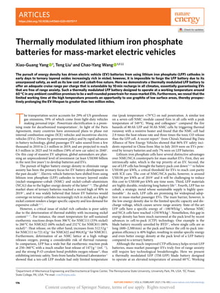
  • 3. Articles Nature Energy corresponding driving range. Under UDDS protocol, the driv- ing range with the two batteries is similar at warm temperatures (decreasing moderately from 290 km at 60 °C to 270 km at 10 °C). At freezing temperatures, however, the cruise range descends rapidly, especially for the EV with the LFP blade battery whose range falls to 158 km at −10 °C and 39 km at −20 °C, as compared with 228 km at −10 °C and 157 km at −20 °C for the EV with the NMC622 battery. The sharp reduction in the cruise range of the LFP battery-powered EV can be attributed to the high mass-transfer resistance in the thick LFP cathode. At the same areal capacity of 3 mAh cm–2 , the thickness of the LFP cathode is 1.6 times that of the NMC622 cathode (Supplementary Table 2). As electrolyte conductivity and diffusivity drop substantially at low temperatures, the thick LFP cathode suffers much higher ionic resistance (Supplementary Fig. 8a) and greater electrolyte transport resistance (Supplementary Fig. 8b). Only half of the LFP cathode in the vicinity of the separator can therefore be fully lithiated at the end of the UDDS cycling at −10 °C (as shown in Supplementary Fig. 8c) whereas the lithiation degree of the NMC622 cathode is quite uniform. The temperature effects on cruise range are more dramatic in highway driving scenarios. Under the US06 protocol, as shown in Fig. 3b,d, the driving range with the LFP battery falls to only 58% of the driving range with the NMC622 battery at 0°C, and this ratio drops further to 30% at −10°C. Such greater temperature effects are attributed to the higher power demand for highway driving, which induces a larger electrolyte concentration gradient in the thick LFP cathode (Supplementary Fig. 8e). Accordingly, only one-fifth of the LFP cathode can be fully lithiated at the end of the US06 cycling at −10°C (Supplementary Fig. 8f). Besides, we should note that regenerative braking, which accounts for ~28% of the cruise range under UDDS protocol and ~20% under US06 protocol, is typically prohibited at low temperatures as it can induce lithium plating (Supplementary Fig. 9); thus, only the solid bars in Fig. 3c,d should be considered as the driving range at <0°C, making the cruise range even lower at freezing temperatures. a b c d Cell Cell Module Pack Pack 200 180 160 140 120 100 160 180 200 220 240 260 280 300 350 400 450 500 550 600 650 700 750 300 250 200 150 100 50 0 Pack-level specific energy (Wh kg –1 ) Pack-level energy density (Wh l –1 ) Cell-level specific energy (Wh kg–1 ) Cell-level energy density (Wh l–1 ) G CTP = 0.75 VCTP = 0.4 VCTP = 0.3 VCTP = 0.2 GCTP = 0.65 GCTP = 0.55 NIO ES8 (2018) Hyundai Kona (2018) Chevy Bolt (2018) Tesla Model 3 LR (2018) Hyundai Ioniq (2018) Jaguar I-PACE (2019) Renault ZE40 (2018) BMW i3 (2018) BMW i3 (2019) Renault ZE50 (2019) Mercedes EQC (2019) BYD Han (2020) (LFP blade battery) Nissan Leaf (2018) Audi E-Tron (2018) Fig. 1 | Cell-to-pack technology. a,b, A schematic illustration of a conventional battery pack (a) and a blade battery pack (b). The conventional battery pack uses cells to build a module and then assembles modules into a pack. A blade battery pack builds on wide and short cells and assembles them directly into a pack, thereby having much higher mass and volume integration efficiencies than the conventional pack. c,d, A summary of the pack- and cell-level gravimetric specific energy (c) and volumetric energy density (d) of the battery packs in state-of-the-art EVs. All parameters of the battery cells and packs needed to calculate these data points, along with the corresponding references, are summarized in Supplementary Table 1. Nature Energy | VOL 6 | February 2021 | 176–185 | www.nature.com/natureenergy 178 Content courtesy of Springer Nature, terms of use apply. Rights reserved
  • 4. Articles Nature Energy Fast charging is widely recognized as the key to eliminating range anxiety. The US Department of Energy has identified 10min extreme fast charging as a crucial enabler of mainstream EV adop- tion. The fundamental limitation of fast charging is lithium plat- ing, which can drastically reduce battery life and even induce safety hazards. Figure 4 displays the cell voltage and anode potential (at the anode–separator interface) of the LFP and NMC622 cells dur- ing charging at different C-rates and temperatures. A standard constant-current–constant-voltage (CCCV) protocol is adopted with an upper cutoff voltage of 3.65V for the LFP cell and 4.2V for the NMC622 cell. As the two cells have the same anode design, their anode potential profiles overlap in the initial constant current charging step. Due to a lower upper voltage, the LFP cell enters the constant voltage step earlier than the NMC622 cell, which leads to a longer charging time (at the same C-rate) but prevents a further drop of the anode potential. As such, the LFP cell is less susceptible to lithium plating and therefore can be charged with a higher rate than the NMC622 cell. For instance, the LFP cell can withstand 3C charging at 25°C, whereas the NMC622 cell can only take 1.5C. We note from Fig. 4 that temperature has a substantial impact on the plating-free maximum charge rate (PF-MCR) of both cells (see also Supplementary Fig. 10). The PF-MCR refers to the maximum charge C-rate required for the anode potential to stay above 0V. We can see that the PF-MCR at 0°C drops to 0.7C for the LFP cell and 0.4C for the NMC622 cell, prolonging the charging time (0–80% SOC) to 80min for the LFP cell and 112min for the NMC622 cell (Fig. 4d). On the other end, elevating cell temperature can boost the fast-charging ability substantially. At 60°C, the PF-MCR rises to 4C for the NMC622 cell and to >6C for the LFP cell (Fig. 4f). The LFP cell at 60°C has no lithium plating even when charging with an aggressive protocol of CV at 3.65V throughout the process. Under such a protocol, it takes only 9.4min to charge from 0 to 80% SOC. It can be concluded that LFP blade batteries—with their high CTP ratios—can deliver comparable specific energy and better energy density at the pack level to NMC batteries; LFP cells are also less susceptible to lithium plating and hence can be charged faster than NMC cells. The most critical challenge to LFP batteries for adoption in passenger EVs is the sharp reduction in cruise range at freezing temperatures due to the high mass-transfer resistance in the thick LFP cathodes. Besides, similar to NMC batteries, LFP cells face the issues of much-reduced power and rechargeability at low temperatures. TM-LFP blade battery We believe that a LFP battery of decent energy density at the pack level, as elaborated above, coupled with a 10min fast rechargeability, is an economical solution to mass-market passenger EVs. To this end, we propose a TM-LFP blade battery designed to operate at an elevated temperature of 60°C in any ambient condition. In practice, this can be implemented by rapid heating before battery operation (EV driving), which is feasible as long as the heating speed is fast. For instance, we reported a self-heating lithium ion battery structure with an embedded nickel foil as an internal heater34 , which achieves a heating speed greater than 1°C per second, meaning that, even in the extreme cold of −30°C, it takes only 90s for the battery to warm up to 60°C before operation (driving). The added weight and cost due to the introduction of nickel foils are negligibly small, estimated to be 1.3% drop in specific energy and 0.47% increase in cost35,36 . Furthermore, this cell structure has been demonstrated viable for mass production and has already been utilized in real-world EVs37 . a b c d 280 240 200 160 120 700 600 500 400 300 1.0 1.5 2.0 2.5 3.0 3.5 4.0 1.0 1.5 2.0 2.5 3.0 3.5 4.0 1.0 1.5 2.0 2.5 3.0 3.5 4.0 1.0 1.5 2.0 2.5 3.0 3.5 4.0 350 300 250 200 150 100 200 180 160 140 120 100 80 Cathode areal capacity (mAh cm–2 ) Cathode areal capacity (mAh cm–2 ) Cathode areal capacity (mAh cm–2 ) Cathode areal capacity (mAh cm–2 ) Cell-level energy density (Wh l –1 ) Pack-level energy density (Wh l –1 ) Cell-level specific energy (Wh kg –1 ) Pack-level specific energy (Wh kg –1 ) NMC622 VDA (VCTP ≈ 0.3–0.4) NMC622 VDA (GCTP ≈ 0.55–0.65) LFP blade (VCTP ≈ 0.6–0.7) LFP blade (GCTP ≈ 0.8–0.9) NMC622 VDA battery LFP blade battery Fig. 2 | Specific energy and energy density at cell and pack levels. a–d, The evolutions of the gravimetric-specific energy (a,b) and volumetric energy density (c,d) of the LFP blade battery and NMC622 prismatic battery (VDA-BEV2 standard) at cell (a,c) and pack (b,d) level as a function of cathode areal capacity. Both cells are under the fixed cell dimensions given in Supplementary Table 2. In all cases the anode and cathode porosities are fixed at 0.27, and the negative-to-positive capacity ratio is fixed at 1.1. Nature Energy | VOL 6 | February 2021 | 176–185 | www.nature.com/natureenergy 179 Content courtesy of Springer Nature, terms of use apply. Rights reserved
  • 5. Articles Nature Energy Operating at an elevated temperature is quite beneficial as the performance of a lithium ion cell is fundamentally affected by the rates of the following physicochemical processes: electrochemical reactions at the surfaces of anode and cathode materials, lithium ion conduction and diffusion in the electrolyte, and solid-state lithium diffusion in anode and cathode particles. Key parameters that gov- ern these processes all depend strongly on temperature, following the Arrhenius law (Supplementary Fig. 11). For instance, LFP mate- rials are known for having the issue of poor solid-state diffusivity and have to be made into nanoparticles for use in lithium ion cells. Elevating temperature from 20°C to 60°C can boost the solid-state diffusivity of LFP by 60-fold (Supplementary Fig. 11) and thereby can substantially mitigate the lithium diffusion resistance in LFP particles. All of the aforementioned physicochemical processes accelerate at the elevated temperature of 60°C, which can bring numerous benefits to an EV, as detailed below. First, operating a cell consistently at 60°C prevents the sharp drop in cruise range at low ambient temperatures, which, as idendified above, is the most critical barrier to LFP blade batter- ies. Supplementary Fig. 12 shows the voltage profiles of a 40kWh TM-LFP battery pack under the UDDS driving cycle at freezing temperatures. The TM-LFP battery is preheated to 60°C before driving, which consumes about 1.35% battery energy per 10°C tem- perature rise according to the previous test results of cells with simi- lar specific energy38 . This energy consumption is used to reset the initial SOC of the TM-LFP battery for the UDDS cycle (for example, it starts at 89.2% SOC in the case of −20°C ambient). Despite the energy consumption for heating, we can see that the TM-LFP bat- tery has much smaller voltage oscillations (that is, lower cell resis- tance) and sustains much longer driving than regular LFP and NMC cells that start the discharge at 100% SOC. Figure 5a summarizes the driving range (calculated by integrating the UDDS velocity profile in Supplementary Fig. 7a over the driving time) at different tem- peratures. We can note that the TM-LFP battery enables a decent cruise range at all ambient conditions. At warm temperatures, the cruise range is about 290km (note that this range can be extended to 400km if the battery is scaled up to 50–55kWh). At cold tem- peratures (for instance, −20°C), despite the 10.8% battery energy consumed for preheating, the TM-LFP battery still delivers a range of 260km, which is far superior to the range with the regular LFP blade battery (13km) and with the conventional NMC622 battery (110km) at the −20°C ambient. The TM-LFP battery is thus able to deliver adequate cruise range per charge in all climatic conditions. Second, the TM-LFP battery exhibits extraordinary power at all ambient temperatures. As shown in Supplementary Figs. 5 and 6, bat- tery power drops exponentially with decreasing temperature, posing a critical challenge to vehicle acceleration and regenerative braking in cold weather. By operating consistently at 60°C, battery power, on the one hand, becomes independent of ambient temperature (Fig. 5b), whereas on the other it is further boosted by 2.4-fold (compared with a b c d 4.2 3.6 3.0 2.4 4.2 3.6 3.0 2.4 4.2 3.6 3.0 2.4 Voltage (V) Voltage (V) Voltage (V) 4.2 3.6 3.0 2.4 4.2 3.6 3.0 2.4 4.2 3.6 3.0 2.4 Voltage (V) Voltage (V) Voltage (V) 350 300 250 200 150 100 50 0 UDDS driving range (km) –20°C –10°C 0°C 10°C 25°C Temperature (°C) 40°C 60°C LFP blade battery NMC622 VDA battery 350 300 250 200 150 100 50 0 US06 driving range (km) –20°C –10°C 0°C 10°C 25°C Temperature (°C) 40°C 60°C 0 1 2 3 4 5 Driving time (h) Driving time (h) 6 7 8 9 10 0 0.5 1.0 1.5 2.0 2.5 25°C 0°C –10°C 25°C 0°C –10°C LFP blade battery NMC622 VDA battery Fig. 3 | Cruise range under city and highway driving in different temperatures. a–d, A comparison of the driving behaviour of an EV (similar to a Nissan Leaf) powered by a 40kWh battery pack composed of either the LFP blade cells or the NMC622 prismatic cells (VDA-BEV2 standard). The cell voltage (a,b) and total driving range (c,d) at different temperatures are shown. Results in a and c are under the UDDS protocol, which represents a city-driving scenario, whereas results in b and d are under the US06 protocol, representative of highway driving. The solid bars in c and d represent the driving range without regenerative braking (replacing the positive values of power in Supplementary Fig. 7 with zero), and the sum of solid and dashed bars represents the driving range with incorporation of regenerative braking. Note that regenerative braking at <0°C is typically prohibited due to the issue of lithium plating (Supplementary Fig. 9). Nature Energy | VOL 6 | February 2021 | 176–185 | www.nature.com/natureenergy 180 Content courtesy of Springer Nature, terms of use apply. Rights reserved
  • 6. Articles Nature Energy the power at 20°C) owing to the enhanced electrochemical reactions and transport processes. Even at 10% SOC, the specific power of the TM-LFP battery still meets the target set forth by the EUCAR on peak specific power for 2030 mass-market EVs (Fig. 5b). Third, the TM-LFP battery enables weather-independent fast charging in 10min (Fig. 5c). As noted above, the PF-MCR of a lith- ium ion cell drops dramatically with the decrease of temperature due to the issue of lithium plating (Supplementary Fig. 10), lead- ing to an increase of charging time (0 to 80% SOC) from 30min at 20°C to 80min at 0°C for the regular LFP blade cell. By elevating cell temperature to 60°C, the same LFP cell can withstand the most aggressive protocol of CV charging at 3.65V throughout the process and yields no lithium plating (Fig. 4f), cutting the charging time to 9.4min. If using the more standard CCCV protocol at 6C rate, it still only takes 10.1min (Fig. 4e). More importantly, such a fast charging can be performed at all ambient temperatures using the heated-charging approach presented in our recent works35,36 . Even if the cell is initially at −30°C, the total time of charging to 80% SOC would be only 10.9min (1.5min for heating from −30°C to 60°C plus 9.4min for charging). The all-climate medium cruise range and readily extendable through 10min fast charging, as offered by the TM-LFP battery, can enable EVs ultimately free of range anxiety. Also note that 6C charging of the 40kWh TM-LFP batteries needs 240kW chargers, which are readily available through Telsa V3 Supercharger Network or the 350kW fast-charge stations recently installed by Electrify America. Most excitingly, the 40kWh TM-LFP battery for a passenger EV free of range anxiety already exceeds cost parity with ICE vehicles. Fourth, the elevated temperature also greatly reduces battery cooling need and thereby simplifies or even eliminates the battery thermal management system (BTMS). The heat balance of a battery cell can be mathematically expressed as: I2 R ¼ h Tcell � Tamb ð Þ ð1Þ where the left-hand-side represents heat generation rate, with I the current and R the cell internal resistance, whereas the right-hand-side represents the heat dissipation rate, with h the heat transfer coefficient and Tcell and Tamb the cell and ambient tempera- tures, respectively. As shown in Fig. 5b, the 10s peak power (at 2.4V constant voltage) of the LFP cell at 60°C is about double of that at 25°C, meaning that the internal cell resistance at 60°C is about half of that at 25°C. As such, the heat generation is reduced by half as cell temperature rises from 25°C to 60°C. On the other end, the driving force for heat dissipation (Tcell –Tamb) is enlarged to 35°C (Tcell at 60°C and Tamb at 25°C). Assuming that a conventional BTMS can maintain cell temperature at 30°C (that is, 5°C tem- perature difference for cooling) in regular operation, the strategy of operating at 60°C boosts the term Tcell –Tamb by seven-fold. Together with the halved heat generation, the value of h for a TM-LFP battery is reduced to one-fourteenth of that for a regular battery pack. In this context, passive air cooling, instead of active liquid cooling, could suffice for a TM-LFP battery pack. Such a simplified BTMS can further improve pack-level energy density and reduce pack cost (for example, a current liquid cooling system accounts for ~5% of battery pack weight39 and costs around US$250 for a 60kWh pack40 ). Million-mile EV Lifespan In the past, it was believed that lithium-ion cells should avoid operating at high temperatures due to the concern of acceler- ated degradation. We recently revealed that cell aging driven by a high temperature depends on the time of the cell at the high tem- perature35 . For a TM-LFP battery, it is exposed to 60°C only dur- ing operation, which is a small fraction of the lifetime of an EV. According to the American Automobile Association41 , Americans spend about 51min behind the wheel per day travelling for 31.5 miles (an average speed of 37mph); thus, the time of an EV on the road, or of a TM-LFP battery at 60°C, is only 3.5% (51min out of 24h) of a vehicle’s lifespan. We should also note that LFP materials are particularly suitable for high-temperature operation, given their superior thermal stability. The primary aging mechanism in a LFP cell is the growth of solid–electrolyte interphase (SEI) on graphite a b c d e f 4.4 4.0 3.6 3.2 2.8 0 10 20 Charging time (min) Charging time (min) Charging time (min) 30 40 0 10 20 Charging time (min) 30 40 Cell voltage (V) 4.4 4.0 3.6 3.2 2.8 Cell voltage (V) 4.4 4.0 3.6 3.2 2.8 Cell voltage (V) 25°C Li plating Li plating Li plating 0°C 60°C LFP, 1.5C LFP, 3C LFP, 0.4C LFP, 0.7C NMC622, 1.5C NMC622, 3C NMC622, 0.4C NMC622, 0.7C LFP, 4C LFP, 6C LFP, CV@3.65V NMC622, 4C NMC622, 6C 0 30 60 90 120 150 Charging time (min) 0 30 60 90 120 150 0 4 8 12 16 Charging time (min) 0 4 8 12 16 0.3 0.2 0.1 –0.1 0 Anode potential (V) 0.3 0.2 0.1 –0.1 0 Anode potential (V) 0.3 0.2 0.1 –0.1 0 Anode potential (V) Fig. 4 | Fast-charging capability at different temperatures. a–f, The evolutions of cell voltage (a,c,e) and anode potential (b,d,f) (at the anode–separator interface) during charging of the blade-type graphite-LFP cell and the prismatic-type (VDA-BEV2 standard) graphite-NMC622 cell at different charge rates and temperatures: 25°C (a,b), 0°C (c,d), 60°C (e,f). The cells are initially at 0% SOC, and the solid circles denote the time of reaching 80% SOC. The LFP and NMC622 cells follow the design information in Supplementary Table 2. Nature Energy | VOL 6 | February 2021 | 176–185 | www.nature.com/natureenergy 181 Content courtesy of Springer Nature, terms of use apply. Rights reserved
  • 7. Articles Nature Energy surfaces, which is mainly a function of temperature, SOC and time. Supplementary Fig. 13 presents the calendar-life data of a widely utilized commercial graphite-LFP cell from Sony42 . Even at 100% SOC, the fastest SEI growth scenario, the cell at 60°C still has a life- time (at 20% capacity loss) of 660 days. For a TM-LFP battery, a total of 660 day operating time at 60°C represents a lifespan of 51 years and 586,080 miles (based on 51min driving time a day at an average speed of 37mph). As the SEI growth rate is proportional to the BET area of graphite (equation (9))43 , the lifetime of a TM-LFP battery can be further enhanced by using graphite with low BET areas (for example, larger particles). In the past, low-BET-area graphite was not typically used in EV batteries, as a reduced surface area increases charge transfer resistance and larger particles lead to higher diffusion resistance. Elevating cell temperature from 20°C to 60°C can boost graph- ite reaction kinetics by 12-fold and graphite solid-state diffusivity 5.6-fold (Supplementary Fig. 11), effectively mitigating the adverse effects due to a reduced BET area. As shown in Supplementary Fig. 14, the increase of graphite particle size has minimal impacts on the cruise range of a TM-LFP battery-powered EV under either the UDDS or US06 protocol (Supplementary Fig. 14a), and a cell with two times the graphite radius at 60°C even has better peak power than the baseline cell at 20°C (Supplementary Fig. 14b). Regarding fast charging, a cell with 1.5 times the graphite radius can still be safely (without lithium plating) charged with the 6C current and 3.65V cutoff voltage of the CCCV protocol at 60°C and takes 10.3min to charge from 0 to 80% SOC (Supplementary Fig. 14c,d), and the cell with two times the graphite radius can be charged to 80% SOC in 11.8min with 6C rate and a lower cutoff voltage of 3.6V (to prevent lithium plating). These results demonstrate that the elevated temperature of 60°C makes the performance of a TM-LFP cell insensitive to graphite particle radius. On the other hand, the particle size of graphite has a considerable impact on SEI growth at 60°C. As shown in Fig. 5d, the calendar life at 20% capacity loss of the above-mentioned graphite-LFP cell at 60°C and 100% SOC can be prolonged to 1,368 days with a 1.5 times the graphite radius, which, based on an average speed of 37mph, corresponds to greater than 1.2 million driving miles for a TM-LFP battery-powered EV. If the graphite radius is doubled, the lifetime at 60°C and 100% SOC soars further to 2,315 days, corresponding to greater than two million miles. It is understood that battery cycling may cause additional deg- radation due to lithium insertion and extraction (for example, active material particle cracking). Dahn et al44,45 . showed that the cycling-induced loss is however lessened at high temperatures and that the capacity loss of cells under cycling and storage almost overlap in the time domain at >40°C. Schimpe et al46 compared the capacity loss of the Sony/Murata LFP cells during cycling and storage and found that the pure cycling-induced loss follows a square-root dependency on an equivalent full cycle (EFC). By extrapolating their data (at 55°C) and assuming 300 miles per EFC, we estimate a ~10% additional capacity loss after two million miles (~6,700 EFCs). Even when adding this cycling-induced loss, the TM-LFP battery with double the graphite radius is still projected to a b c d 350 300 250 200 150 100 50 0 –20°C –10°C 0°C 10°C Ambient temperature (°C) Ambient temperature (°C) Ambient temperature (°C) 25°C 40°C 60°C UDDS driving range (km) LFP blade TM-LFP blade NMC622 VDA 2,000 1,600 1,200 800 400 0 –20 –10 0 10 20 30 40 50 60 Pack-level specific power (W kg –1 ) TM-LFP blade battery (GCTP ≈ 0.9) LFP blade battery (GCTP ≈ 0.85) NMC622 VDA battery (GCTP ≈ 0.65) 100 90 80 70 Capacity retention (%) 0 400 800 1,200 1,600 2,000 2,400 Days Storage at 60°C, 100% SOC Sony/Murata commercial cell ECT model, Baseline ECT model, 1.5x graphite radius ECT model, 2.0x graphite radius 120 100 80 60 40 20 0 0 10 20 30 40 50 60 NMC622 VDA battery LFP blade battery TM-LFP blade battery Charge time to 80% SOC (min) EUCAR 2030 target Fig. 5 | All-climate cruise range, remarkable power and 10min fast charging with a TM-LFP blade battery. a–c, Comparisons of the TM-LFP blade battery with the regular LFP blade battery and the conventional NMC622 prismatic battery (VDA-BEV2 standard) in terms of: cruise range under the UDDS at different ambient temperatures for an EV with a 40kWh battery composed of either of the three types of cells (a); pack-level specific power at 10% SOC (b); and the minimum time to charge from 0 to 80% SOC without lithium plating (c). The TM-LFP blade battery is preheated from ambient temperature to 60°C before an operation, which consumes 1.35% SOC per 10°C temperature rise (used for calculating the initial SOC in Fig. 5a; for instance, the TM-LFP battery at 25°C starts at 95.3% SOC). The heating speed is 1°C per second, and the heating time is included in the charging time of the TM-LFP battery shown in Fig. 5c. d, The calendar life of a graphite-LFP battery with different graphite particle sizes at 60°C and 100% SOC. The solid symbols represent the experimental data from the literature on a commercial cell, and the lines are results predicted by a calibrated ECT aging model (see Supplementary Fig. 13). Nature Energy | VOL 6 | February 2021 | 176–185 | www.nature.com/natureenergy 182 Content courtesy of Springer Nature, terms of use apply. Rights reserved
  • 8. Articles Nature Energy retain ~70% capacity after two million miles, which is greater than 16 times the warranty on many commercial EV batteries (for exam- ple, Tesla Model 3, 70% capacity for eight years or 120,000 miles). The TM-LFP battery therefore offers an opportunity to use graph- ite of low BET areas, enabling high performance and long lifetime simultaneously. Conclusions Figure 6 summarizes the performance metrics of the above three batteries: the NMC622 VDA battery, the regular LFP blade bat- tery and the TM-LFP blade battery. With the improved CTP ratios, the LFP blade battery delivers comparable specific energy and better energy density at the pack level to the conventional NMC battery, offering a medium cruise range for passenger EVs at warm temperatures; LFP cells can also be charged faster than NMC cells due to a lower cutoff voltage, which helps prevent lithium plating. The primary challenge to LFP blade batteries for use in passenger EVs is the sharp reduction in cruise range at low temperatures, along with a drop in peak power and PF-MCR. Designed for operating at 60 °C in any ambient conditions, the TM-LFP battery not only tackles the issues at low temperatures but further boosts battery power and fast charging ability, lead- ing to adequate cruise range coupled with 10 min fast recharge in all weather conditions. The elevated temperature also simplifies BTMS due to a 14-fold reduction in battery cooling need, which further enhances CTP efficiency and reduces cost. Moreover, the elevated operating temperature with a limited exposure time presents a way to achieving high performance and long lifetime simultaneously and makes it viable for using graphite of low BET areas, which can prospectively prolong the lifetime of an EV to over two million miles. The world is currently at the inflection point of massive EV penetration. The TM-LFP blade battery presented in this work offers adequate cruise range per charge that is readily extendable through a 10 min recharge, and does so in all climates. We believe that such a TM-LFP battery is a viable alternative to energy-dense NMC/NCA batteries or carrying big batteries (for example, 100 kWh) on board to free EVs from range anxiety. Furthermore, the LFP battery enjoys unsurpassed advantages in safety, cost and containing no cobalt or nickel. Figure 6 shows that the TM-LFP battery can fulfil all major criteria required for EVs, presenting enormous potential for large-scale adoption in mass-market pas- senger EVs. Methods ECT model. The physics-based ECT model solves the following governing equations: Charge conservation in solid electrodes: ∇  σs∇ϕs ¼ jtot ð2Þ where ϕs is the solid-phase potential, σs is the electronic conductivity of the solid and jtot is the total volumetric current density. Charge conservation in electrolyte: ∇  κe∇ϕe þ ∇  κD∇ ln ce ð Þ ¼ �jtot ð3Þ 50 100 150 200 100 200 300 400 300 600 900 1,200 300 600 900 1,200 120 80 40 0 120 80 40 0 400 800 1,200 1,600 7 6 5 4 3 175 150 125 100 75 Low temperature charge time (min) (0°C, 0–80% SOC) Low temperature peak power (Wh kg–1 ) (Pack level,10%SOC, –20°C) Peak power (Wh kg–1 ) (Pack level,10%SOC, 25°C) Energy density (Wh l–1 ) (Pack level) Specific energy (Wh kg–1 ) (Pack level) Charge time (min) (25°C, 0–80% SOC) Calendar life (days) (60°C, 100% SOC) Safety (EUCAR level) Cost (US$ per kWh) NMC622 VDA battery Regular LFP blade battery TM-LFP blade battery Fig. 6 | TM LFP blade battery fulfils all main criteria required for mass-market EVs. Comparisons of the TM-LFP blade battery (red), regular LFP blade battery (blue) and NMC622 prismatic battery (grey, VDA-BEV2 standard) under various performance criteria. The cells have an areal capacity of 3 mAh cm–2 (Supplementary Table 2). The specific energy and power are at the pack level, assuming a GCTP of 0.65 for the NMC622 battery, 0.85 for the regular LFP blade battery and 0.9 for the TM-LFP blade battery (with a simplified thermal management system). The temperatures in this figure refer to ambient temperatures. The TM-LFP battery refers to the cell with 1.5 times the graphite radius. The data points are from Fig. 2b for specific energy, Fig. 2d for energy density, Supplementary Figs. 5f and 14b for peak power, Fig. 4 and Supplementary Fig. 14d for charge time, and Fig. 5d for calendar life. The safety data are based on the EUCAR safety levels defined in ref. 32 . The battery cost are based on ref. 3 for an NMC battery and ref. 24 for a LFP battery, and the TM-LFP battery can further reduce cost by simplifying battery thermal management system (~US$250 for a 60 kWh battery pack40 ). Nature Energy | VOL 6 | February 2021 | 176–185 | www.nature.com/natureenergy 183 Content courtesy of Springer Nature, terms of use apply. Rights reserved
  • 9. Articles Nature Energy where ϕe is the electrolyte-phase potential, κe and κD are the ionic conductivity and diffusional ionic conductivity of the electrolyte, respectively, and ce is the concentration of the electrolyte. Mass conservation in electrolyte: ∂ εce ð Þ ∂t ¼ ∇  De∇ce ð Þ þ 1 � tþ F jtot ð4Þ where ε is electrode porosity, t is time, De is the diffusivity of the electrolyte, t+ the transference number and F is the Faraday constant. Mass conservation in active materials: ∂cs ∂t ¼ 1 r2 ∂ ∂r Dsr2 ∂cs ∂r ð5Þ where cs and Ds are the lithium concentration and diffusivity in solid active materials, respectively, and r is the particle radius. Energy conservation: mCp dT dt ¼ Q þ hA T � Tamb ð Þ ð6Þ where T is cell temperature, m, Cp and A are cell mass, thermal capacity and surface area, respectively, Q is heat generation rate, h is heat transfer coefficient, and Tamb is ambient temperature. The total volumetric current density, jtot, is the sum of the current density of the main and side reactions. The main reaction here refers to lithium intercalation/ deintercalation, whose current density is calculated by the Butler–Volmer equation: jm ¼ ai0;m exp αaF RT ηm � exp � αcF RT ηm ð7Þ where i0,m and ηm are the exchange current density and overpotential of the main reactions, respectively, αa and αc are the anodic and cathodic charge transfer coefficients, and a is the specific surface area (BET area), which depends on the volume fraction (εAM) and r of the active materials (AM): a ¼ 3εAM r ð8Þ Solid–electrolyte interphase growth in the anode is considered as a side reaction in this model to account for cell aging, whose current density is calculated via the Tafel equation: jSEI ¼ �aFk0;SEIcs EC exp � αc;SEIF RT ηSEI ð9Þ where k0,SEI is a kinetic rate constant and cs EC I is the concentration of ethylene carbonate (EC) on the surface of graphite, which is calculated based on the mass conservation of EC: �DEC cs EC � cbulk EC δSEI ¼ � jSEI F ð10Þ where DEC and cbulk EC I are the diffusivity and bulk concentration of EC, respectively, and δSEI is the SEI layer thickness. Model validation The above model is used to predict the performance of two types of cells: a graphite-LFP cell and a graphite-NMC622 cell. We per- formed a set of validations to calibrate the model parameters to reasonably predict the characteristics of LFP and NMC622 cells. The model for the graphite-NMC622 cell was validated against the experimental data of a 10Ah pouch cell presented in refs. 47,48 , and the model for the graphite-LFP cell was validated against the data of a commercial 20Ah cell given in refs. 49,50 . The model validation includes comparing with the experimental data of (1) charge and discharge with various C-rates at 25°C and (2) charge and discharge with 1C rate at various ambient temperatures. As can be seen from Supplementary Figs. 1–4, both the cell voltage and temperature can be predicted reasonably well under all these conditions, dem- onstrating that the models can well capture the electrochemical and thermal behaviours of LFP and NMC622 cells. The calibrated models are then used to predict the performance of the blade-type graphite-LFP cell and the VDA-type graphite-NMC622 cell, follow- ing the cell design information in Supplementary Table 2. The aging model is validated against the calendar aging data of a commercial graphite-LFP cell from Sony/Murata presented in ref. 42 . We can see from Supplementary Fig. 13 that the model well pre- dicts the calendar life of the cell at various temperatures and SOCs. The calibrated model was then applied to predict the calendar life of cells with low BET-area graphite (Fig. 5d), changing only the radius of graphite particles. Vehicle dynamics model The vehicle dynamics model in ref. 51 is adopted to convert the US EPA-defined velocity profiles for the UDDS and US06 driving cycles to battery power profiles (Supplementary Fig. 7). Here we used the specifications of Nissan Leaf (with 40kWh battery) to calculate the power at the wheels: PwheelsðtÞ ¼ mV dvðtÞ dt þ mVg cosðθÞ Cr 1;000 ðc1vðtÞ þ c2Þ þ 1 2 ρairAf CDv2 ðtÞ þ mVg sinðθÞ vðtÞ ð11Þ where mv is the vehicle mass (1,995kg), v(t) is the velocity (in metres per second), g is the gravity of Earth (9.8ms–2 ), θ is climbing angle (assumed to be 0), Cr =1.75, c1 =0.0328 and c2 =4.575 are rolling resistance parameters, ρair is the air density (1.225kgm–3 ), Af is the front area of the vehicle (2.7356m2 ) and CD is the aerodynamic drag coefficient (0.28). The power of the battery pack in traction and regenerative brak- ing modes is then calculated as: Traction mode: Pbatt ¼ Pwheels= ηT ηmd ð Þ ð12aÞ Regenerative braking mode: Pbatt ¼ Pwheelsηrb ð12bÞ where ηT is the transmission efficiency (92%), ηmd is the efficiency of the electric motor (91%) and ηrb is the efficiency of regenera- tive braking (82%). The calculated battery pack power is divided by the number of cells in the pack to calculate the power of single cells, which is then implemented in the above ECT models. In this work we study a 40kWh battery pack, which consists of either 62 of the 202Ah LFP blade cells or 69 of the 158Ah NMC622 VDA cells in Supplementary Table 2. The driving cycle power profiles are repeated until the single-cell voltage reaches the cutoff value (2.4V for the LFP cell and 2.7V for the NMC622 cell). The driving range shown in Figs. 3 and 5 are calculated by integrating the velocity pro- files over time. Data availability All relevant data are included in the paper and its Supplementary Information. Source data are provided with this paper. Code availability The case files for the cell performance and degradation simulations on Autolion-1D v7.0 are publicly available at https://github.com/ECECPSU/TMLFP Received: 3 August 2020; Accepted: 1 December 2020; Published online: 18 January 2021 References 1. Fast Facts: US Transportation Sector Greenhouse Gas Emissions (1990–2018) (US EPA, 2019); https://nepis.epa.gov/Exe/ZyPDF.cgi?Dockey=P100ZK4P.pdf 2. Needell, Z. A., McNerney, J., Chang, M. T. Trancik, J. E. Potential for widespread electrification of personal vehicle travel in the United States. Nat. Energy 1, 16112 (2016). 3. Electric Vehicle Outlook 2020 (BloombergNEF, 2020); https://about.bnef.com/ electric-vehicle-outlook/ 4. Lienert, P. Chan, C. Global automakers investing at least $300 billion on batteries and EVs. Reuters (2019); https://graphics.reuters.com/AUTOS- INVESTMENT-ELECTRIC/010081ZB3HD/index.html 5. Whittingham, M. S. Lithium batteries and cathode materials. Chem. Rev. 104, 4271–4302 (2004). 6. Nitta, N., Wu, F., Lee, J. T. Yushin, G. Li-ion battery materials: present and future. Mate. Today 18, 252–264 (2015). Nature Energy | VOL 6 | February 2021 | 176–185 | www.nature.com/natureenergy 184 Content courtesy of Springer Nature, terms of use apply. Rights reserved
  • 10. Articles Nature Energy 7. Schmuch, R., Wagner, R., Hörpel, G., Placke, T. Winter, M. Performance and cost of materials for lithium-based rechargeable automotive batteries. Nat. Energy 3, 267–278 (2018). 8. Li, M., Lu, J., Chen, Z. Amine, K. 30 Years of lithium-ion batteries. Adv. Mater. 30, 1800561 (2018). 9. Ding, Y., Cano, Z. P., Yu, A., Lu, J. Chen, Z. Automotive Li-ion batteries: current status and future perspectives. Electrochem. Energy Rev. 2, 1–28 (2019). 10. Andre, D. et al. Future generations of cathode materials: an automotive industry perspective. J. Mater. Chem. A 3, 6709–6732 (2015). 11. LFP market share drops in 2019 but expect a comeback with cell-to-pack. Adamas Intelligence (4 March 2020); https://www.adamasintel.com/lfp-market- 2019-cell-to-pack-comeback/ 12. Sun, Y.-K. et al. High-energy cathode material for long-life and safe lithium batteries. Nat. Mater. 8, 320–324 (2009). 13. Olivetti, E. A., Ceder, G., Gaustad, G. G. Fu, X. Lithium-ion battery supply chain considerations: analysis of potential bottlenecks in critical metals. Joule 1, 229–243 (2017). 14. Manthiram, A., Knight, J. C., Myung, S.-T., Oh, S.-M. Sun, Y.-K. Nickel-rich and lithium-rich layered oxide cathodes: progress and perspectives. Adv. Energy Mater. 6, 1501010 (2016). 15. Manthiram, A., Song, B. Li, W. A perspective on nickel-rich layered oxide cathodes for lithium-ion batteries. Energy Storage Mater. 6, 125–139 (2017). 16. Xiong, R., Ma, S., Li, H., Sun, F. Li, J. Toward a safer battery management system: a critical review on diagnosis and prognosis of battery short circuit. iScience 23, 101010 (2020). 17. Feng, X., Ren, D., He, X. Ouyang, M. Mitigating thermal runaway of lithium-ion batteries. Joule 4, 743–770 (2020). 18. Noh, H.-J., Youn, S., Yoon, C. S. Sun, Y.-K. Comparison of the structural and electrochemical properties of layered Li[NixCoyMnz]O2 (x = 1/3, 0.5, 0.6, 0.7, 0.8 and 0.85) cathode material for lithium-ion batteries. J. Power Sources 233, 121–130 (2013). 19. Yamada, A., Chung, S. C. Hinokuma, K. Optimized LiFePO4 for lithium battery cathodes. J. Electrochem. Soc. 148, A224 (2001). 20. Zaghib, K. et al. Enhanced thermal safety and high power performance of carbon-coated LiFePO4 olivine cathode for Li-ion batteries. J. Power Sources 219, 36–44 (2012). 21. Lamb, J., Torres-Castro, L., Stanley, J., Grosso, C. Gray, L. S. Evaluation of Multi-cell Failure Propagation SAND-2020-2802 (Sandia National Laboratories, 2020); https://doi.org/10.2172/1605985 22. Wang, Z., Zhu, K., Hu, J. Wang, J. Study on the fire risk associated with a failure of large-scale commercial LiFePO4/graphite and LiNixCoyMn1-x-yO2/ graphite batteries. Energy Sci. Eng. 7, 411–419 (2019). 23. New Energy Vehicles Safety Monitoring Results Report (National Big Data Alliance of New Energy Vehicles, 2019). 24. Morris, J. Tesla’s shift to cobalt-free batteries is its most important move yet. Forbes (11 July 2020); https://www.forbes.com/sites/jamesmorris/2020/07/11/ teslas-shift-to-cobalt-free-batteries-is-its-most-important-move-yet/ 25. Mullaney, T. Tesla and the science behind the next-generation, lower-cost, ‘million-mile’ electric-car battery. CNBC TECH TRENDS (30 June 2020); https://www.cnbc.com/2020/06/30/tesla-and-the-science-of-low-cost-next- gen-ev-million-mile-battery.html 26. Takahashi, M., Ohtsuka, H., Akuto, K. Sakurai, Y. Confirmation of long-term cyclability and high thermal stability of LiFePO4 in prismatic lithium-ion cells. J. Electrochem. Soc. 152, A899 (2005). 27. Wang, C., He, L., Sun, H., Lu, P. Zhu, Y. Battery pack, vehicle and energy storage device. China Patent CN110165118B (2019). 28. He, K., Jiang, W., Wang, X. Wen, A. Single battery, power battery pack and vehicle. China Patent CN110364675A (2019). 29. Jiang, L., Yang, K., Zhu, Y. Zhu, J. Electric connector and battery comprising the same. United States Patent US20170346065A1 (2017). 30. Kwon, M., Choi, J., Kwon, K., Do, E. Lee, Y. Complex electrode assembly including plurality of electrode assemblies and electrochemical device comprising the complex electrode assembly. United States Patent US20200020922A1 (2020). 31. Gallagher, K. G. et al. Optimizing areal capacities through understanding the limitations of lithium-ion electrodes. J. Electrochem. Soc. 163, A138–A149 (2015). 32. Battery Requirements for Future Automotive Applications (EUCAR, 2019); https://eucar.be/wp-content/uploads/2019/08/20190710-EG-BEV-FCEV-Batter y-requirements-FINAL.pdf 33. Dynamometer Drive Schedules. United States Environmental Protection Agency https://www.epa.gov/vehicle-and-fuel-emissions-testing/ dynamometer-drive-schedules 34. Wang, C. Y. et al. Lithium-ion battery structure that self-heats at low temperatures. Nature 529, 515–518 (2016). 35. Yang, X. G. et al. Asymmetric temperature modulation for extreme fast charging of lithium-ion batteries. Joule 3, 3002–3019 (2019). 36. Yang, X. G., Zhang, G., Ge, S. Wang, C. Y. Fast charging of lithium-ion batteries at all temperatures. Proc. Natl Acad. Sci. USA 115, 7266–7271 (2018). 37. Yang, X. et al. All-climate battery technology for electric vehicles: inching closer to the mainstream adoption of automated driving. IEEE Electrific. Mag. 7, 12–21 (2019). 38. Zhang, G. et al. Rapid self-heating and internal temperature sensing of lithium-ion batteries at low temperatures. Electrochim. Acta 218, 149–155 (2016). 39. Nelson, P. A., Ahmed, S., Gallagher, K. G. Dees, D. W. Modeling the Performance and Cost of Lithium-Ion Batteries for Electric-Drive Vehicles 3rd edn ANL/CSE-19/2 (Argonne National Laboratory, 2020). 40. Lutsey, N. Nicholas, M. Update on Electric Vehicle Costs in the United States Through 2030 1–12 (International Council on Clean Transportation, 2019). 41. Americans Spend an Average of 17,600 Minutes Driving Each Year (American Automobile Association, 2016); https://newsroom.aaa.com/2016/09/ americans-spend-average-17600-minutes-driving-year/ 42. Naumann, M., Schimpe, M., Keil, P., Hesse, H. C. Jossen, A. Analysis and modeling of calendar aging of a commercial LiFePO4/graphite cell. J. Energy Storage 17, 153–169 (2018). 43. Smith, A. J., Burns, J. C., Zhao, X., Xiong, D. Dahn, J. R. A high precision coulometry study of the SEI growth in Li/graphite cells. J. Electrochem. Soc. 158, A447 (2011). 44. Harlow, J. E. et al. A wide range of testing results on an excellent lithium-ion cell chemistry to be used as benchmarks for new battery technologies. J. Electrochem. Soc. 166, A3031–A3044 (2019). 45. Cheng, J. H., Harlow, J. E., Johnson, M. B., Gauthier, R. Dahn, J. R. Effect of duty cycle on the lifetime of single crystal LiNi0.5Mn0.3Co0.2O2/graphite lithium-ion cells. J. Electrochem. Soc. 167, 130529 (2020). 46. Schimpe, M. et al. Comprehensive modeling of temperature-dependent degradation mechanisms in lithium iron phosphate batteries. J. Electrochem. Soc. 165, A181–A193 (2018). 47. Wang, C. Y. et al. A fast rechargeable lithium-ion battery at subfreezing temperatures. J. Electrochem. Soc. 163, A1944–A1950 (2016). 48. Yang, X. G., Leng, Y., Zhang, G., Ge, S. Wang, C. Y. Modeling of lithium plating induced aging of lithium-ion batteries: transition from linear to nonlinear aging. J. Power Sources 360, 28–40 (2017). 49. Mastali, M., Farkhondeh, M., Farhad, S., Fraser, R. A. Fowler, M. Electrochemical modeling of commercial LiFePO4 and graphite electrodes: kinetic and transport properties and their temperature dependence. J. Electrochem. Soc. 163, A2803–A2816 (2016). 50. Mastali, M. et al. Electrochemical-thermal modeling and experimental validation of commercial graphite/LiFePO4 pouch lithium-ion batteries. Int. J. Therm. Sci. 129, 218–230 (2018). 51. Fiori, C., Ahn, K. Rakha, H. A. Power-based electric vehicle energy consumption model: model development and validation. Appl. Energy 168, 257–268 (2016). Acknowledgements Financial support from the US Department of Energy’s Office of Energy Efficiency and Renewable Energy (EERE) under award no. DE-EE0008355 and the William E. Diefenderfer Endowment is gratefully acknowledged. We are also grateful to Gamma Technologies for providing licences to GT-Autolion software, with which we performed the ECT modelling. Author contributions X.G.Y and C.Y.W. conceived the idea and wrote the manuscript. X.G.Y. designed and performed the modelling studies. All authors contributed to analyses of the results. Competing interests The authors declare no competing interests. Additional information Supplementary information is available for this paper at https://doi.org/10.1038/ s41560-020-00757-7. Correspondence and requests for materials should be addressed to C.-Y.W. Peer review information Nature Energy thanks Partha Mukherjee, Kandler Smith and Karim Zaghib for their contribution to the peer review of this work. Reprints and permissions information is available at www.nature.com/reprints. Publisher’s note Springer Nature remains neutral with regard to jurisdictional claims in published maps and institutional affiliations. © The Author(s), under exclusive licence to Springer Nature Limited 2021 Nature Energy | VOL 6 | February 2021 | 176–185 | www.nature.com/natureenergy 185 Content courtesy of Springer Nature, terms of use apply. Rights reserved
  • 11. 1. 2. 3. 4. 5. 6. Terms and Conditions Springer Nature journal content, brought to you courtesy of Springer Nature Customer Service Center GmbH (“Springer Nature”). Springer Nature supports a reasonable amount of sharing of research papers by authors, subscribers and authorised users (“Users”), for small- scale personal, non-commercial use provided that all copyright, trade and service marks and other proprietary notices are maintained. By accessing, sharing, receiving or otherwise using the Springer Nature journal content you agree to these terms of use (“Terms”). For these purposes, Springer Nature considers academic use (by researchers and students) to be non-commercial. These Terms are supplementary and will apply in addition to any applicable website terms and conditions, a relevant site licence or a personal subscription. These Terms will prevail over any conflict or ambiguity with regards to the relevant terms, a site licence or a personal subscription (to the extent of the conflict or ambiguity only). For Creative Commons-licensed articles, the terms of the Creative Commons license used will apply. We collect and use personal data to provide access to the Springer Nature journal content. We may also use these personal data internally within ResearchGate and Springer Nature and as agreed share it, in an anonymised way, for purposes of tracking, analysis and reporting. We will not otherwise disclose your personal data outside the ResearchGate or the Springer Nature group of companies unless we have your permission as detailed in the Privacy Policy. While Users may use the Springer Nature journal content for small scale, personal non-commercial use, it is important to note that Users may not: use such content for the purpose of providing other users with access on a regular or large scale basis or as a means to circumvent access control; use such content where to do so would be considered a criminal or statutory offence in any jurisdiction, or gives rise to civil liability, or is otherwise unlawful; falsely or misleadingly imply or suggest endorsement, approval , sponsorship, or association unless explicitly agreed to by Springer Nature in writing; use bots or other automated methods to access the content or redirect messages override any security feature or exclusionary protocol; or share the content in order to create substitute for Springer Nature products or services or a systematic database of Springer Nature journal content. In line with the restriction against commercial use, Springer Nature does not permit the creation of a product or service that creates revenue, royalties, rent or income from our content or its inclusion as part of a paid for service or for other commercial gain. Springer Nature journal content cannot be used for inter-library loans and librarians may not upload Springer Nature journal content on a large scale into their, or any other, institutional repository. These terms of use are reviewed regularly and may be amended at any time. Springer Nature is not obligated to publish any information or content on this website and may remove it or features or functionality at our sole discretion, at any time with or without notice. Springer Nature may revoke this licence to you at any time and remove access to any copies of the Springer Nature journal content which have been saved. To the fullest extent permitted by law, Springer Nature makes no warranties, representations or guarantees to Users, either express or implied with respect to the Springer nature journal content and all parties disclaim and waive any implied warranties or warranties imposed by law, including merchantability or fitness for any particular purpose. Please note that these rights do not automatically extend to content, data or other material published by Springer Nature that may be licensed from third parties. If you would like to use or distribute our Springer Nature journal content to a wider audience or on a regular basis or in any other manner not expressly permitted by these Terms, please contact Springer Nature at onlineservice@springernature.com