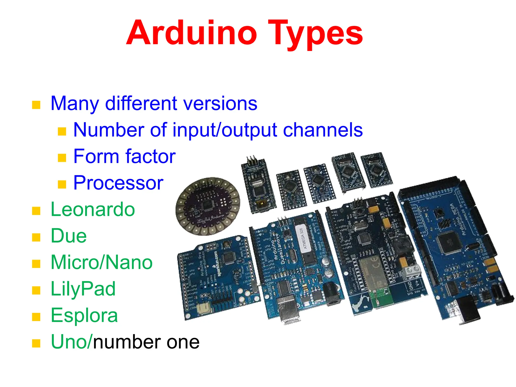
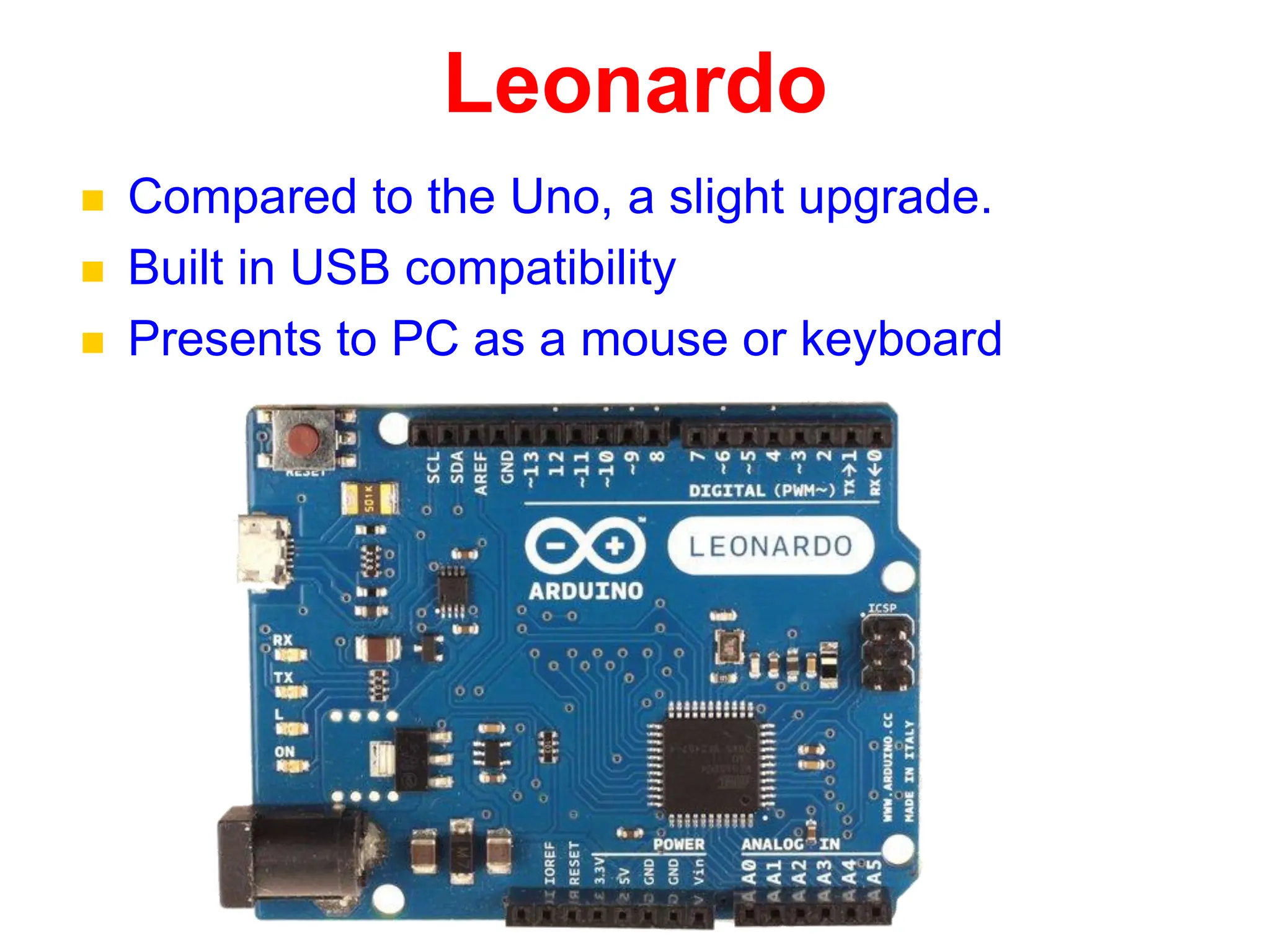
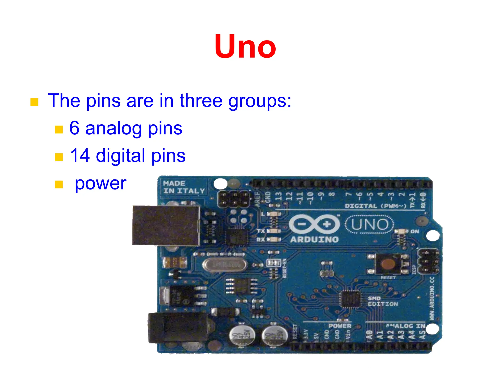
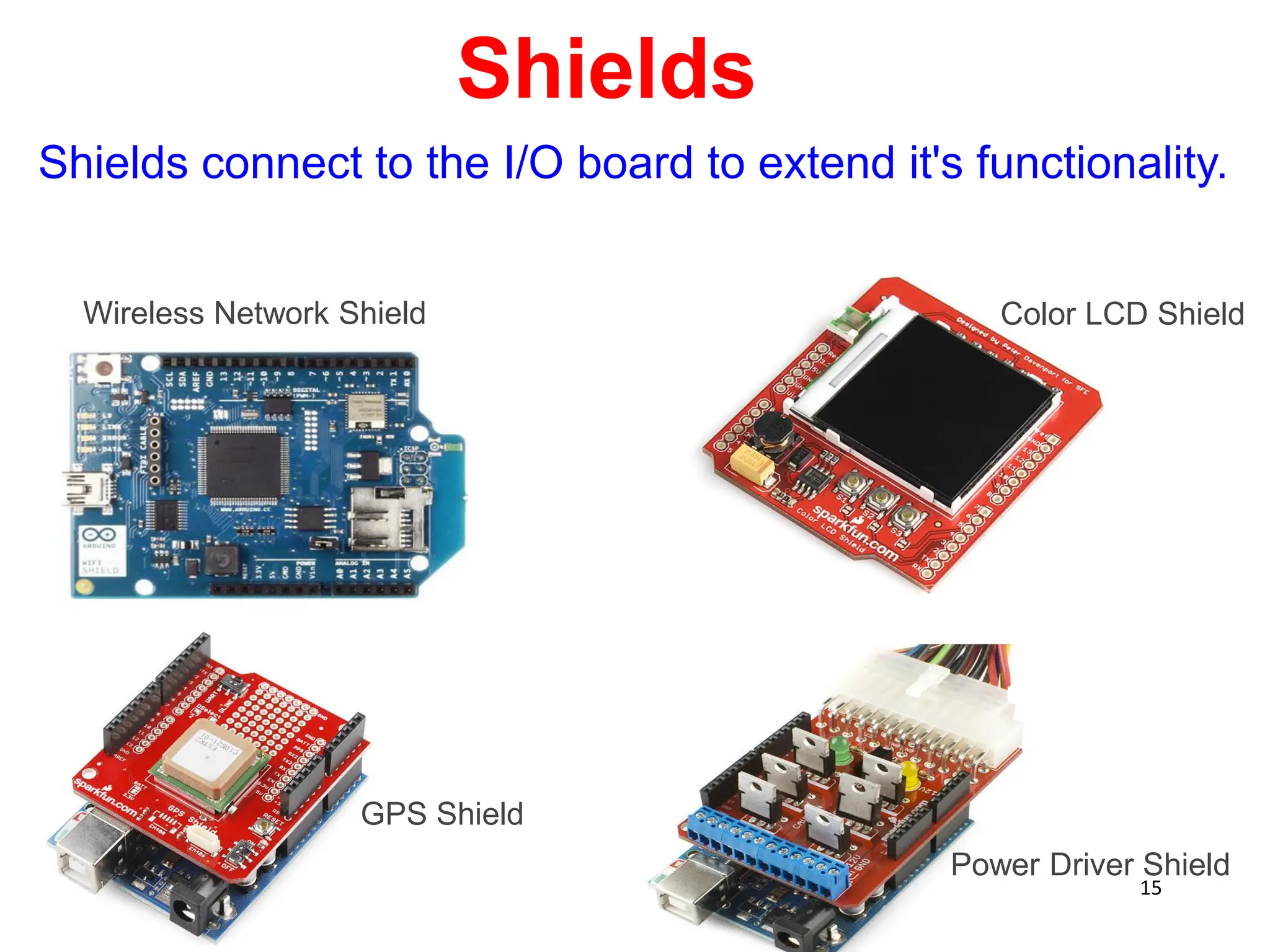
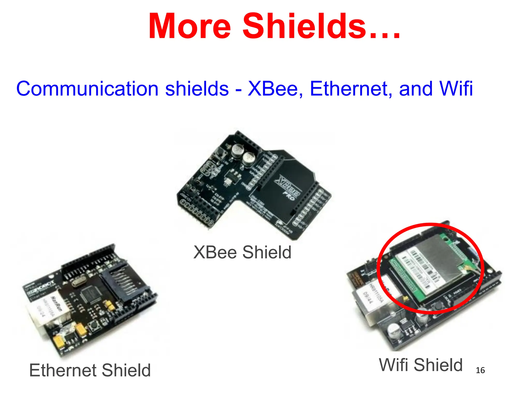
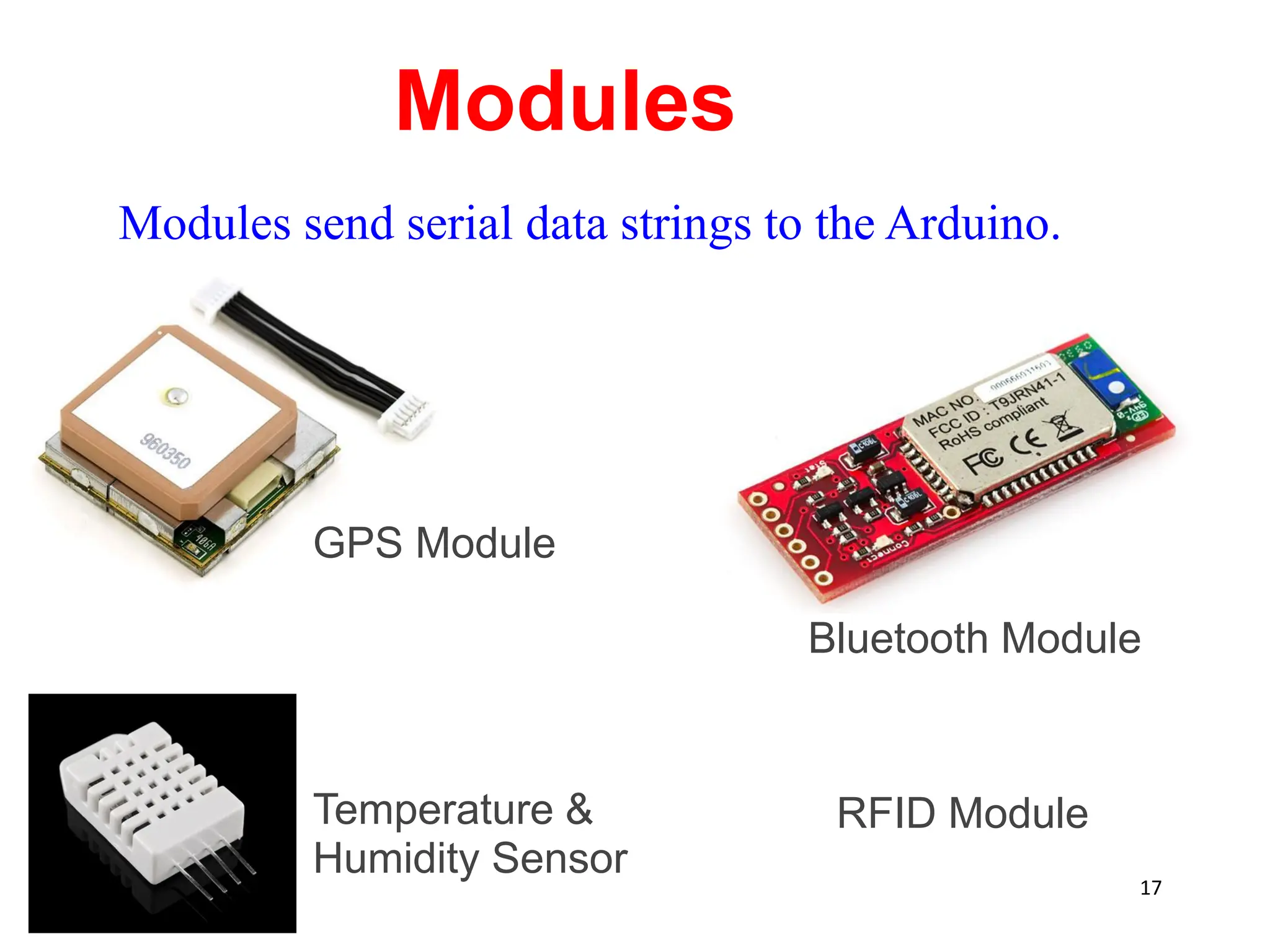
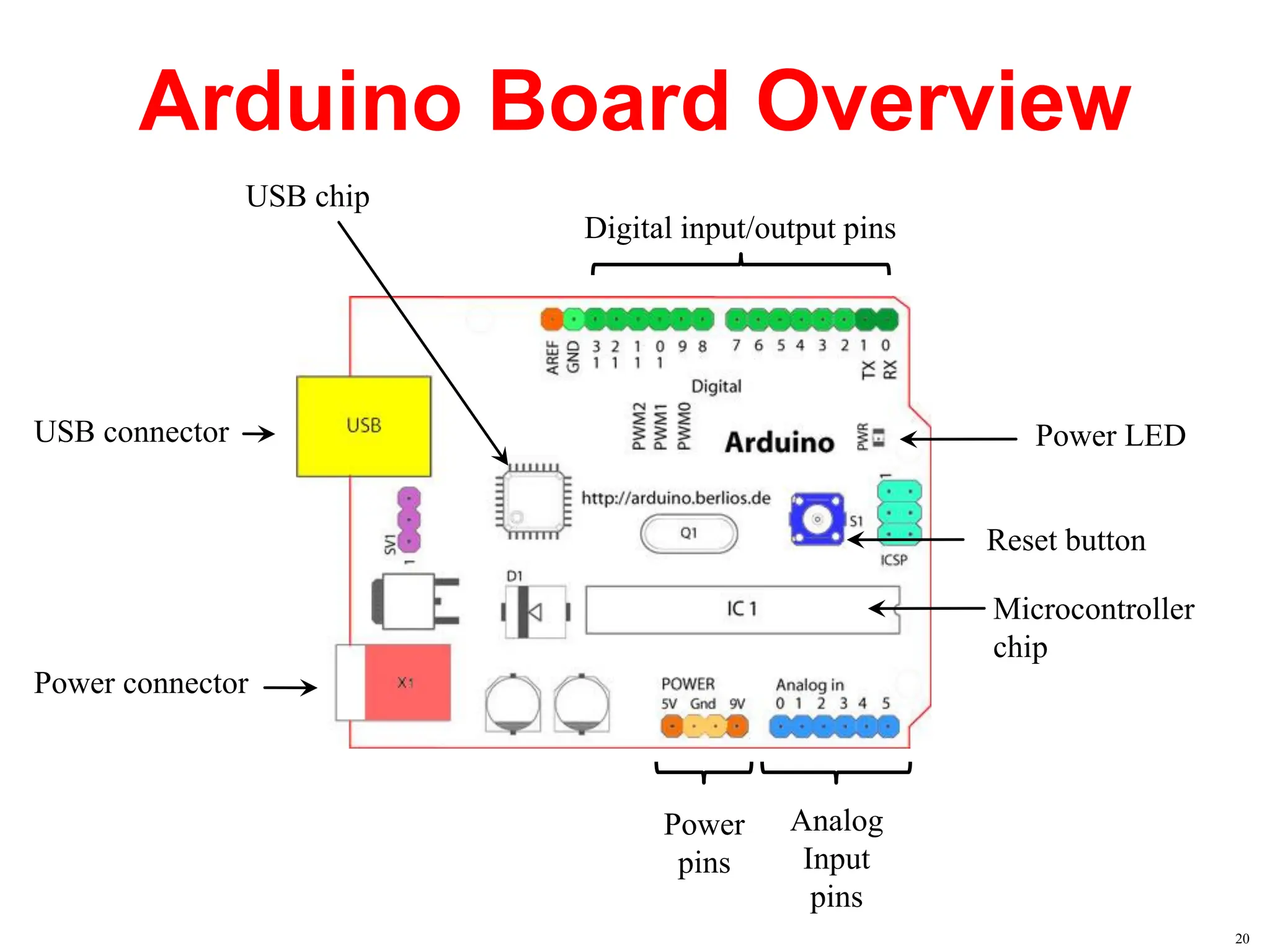
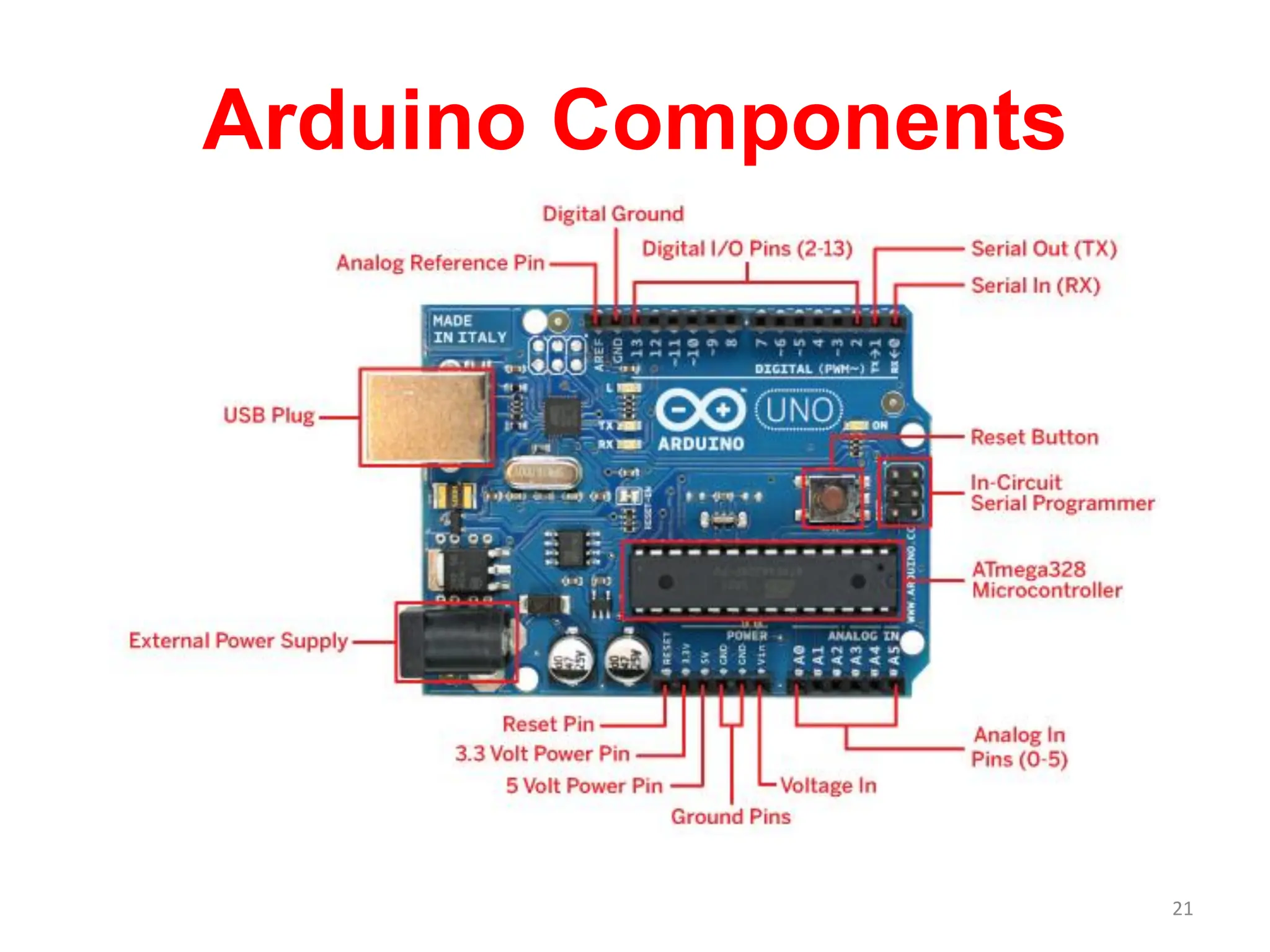
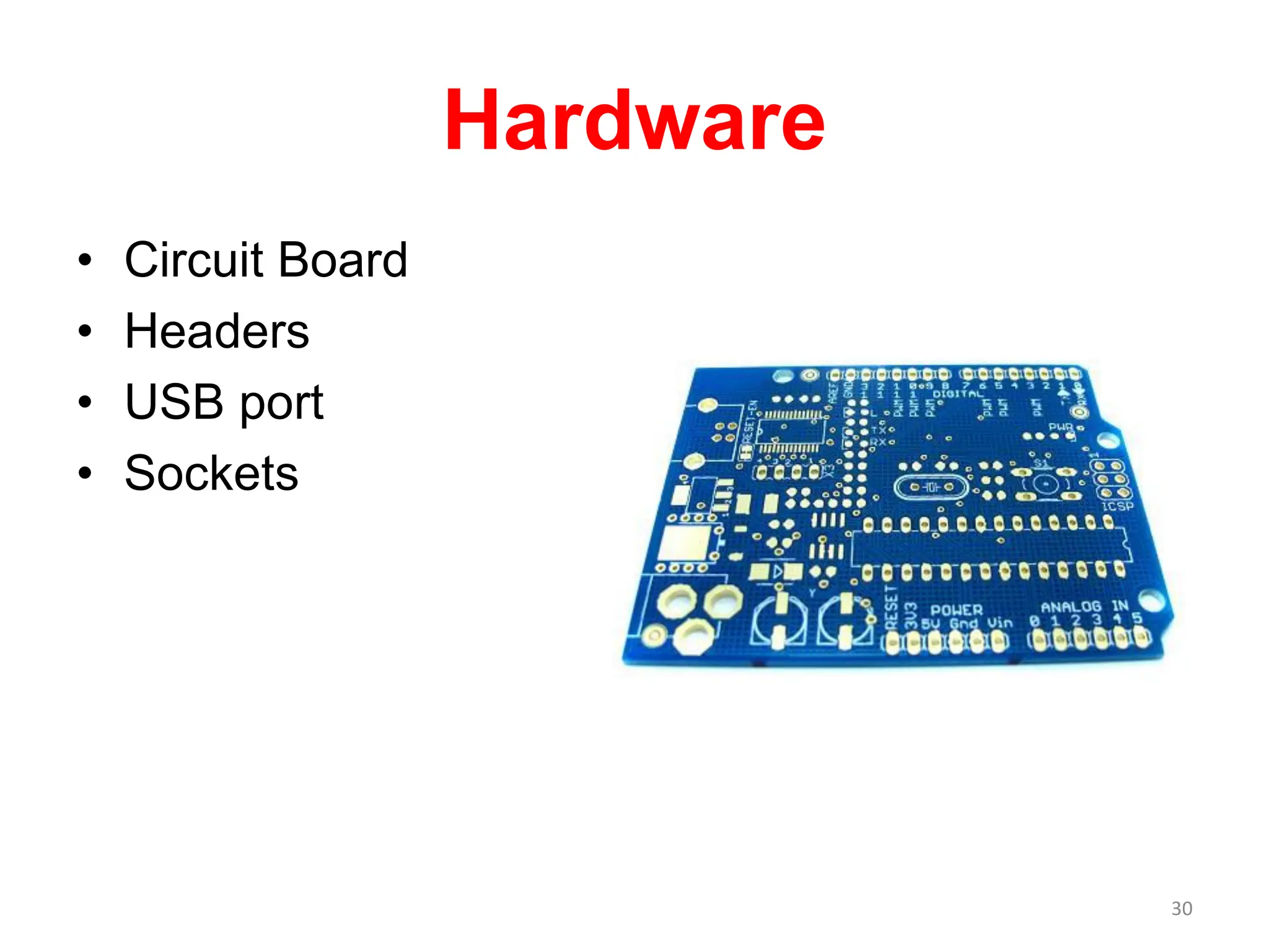
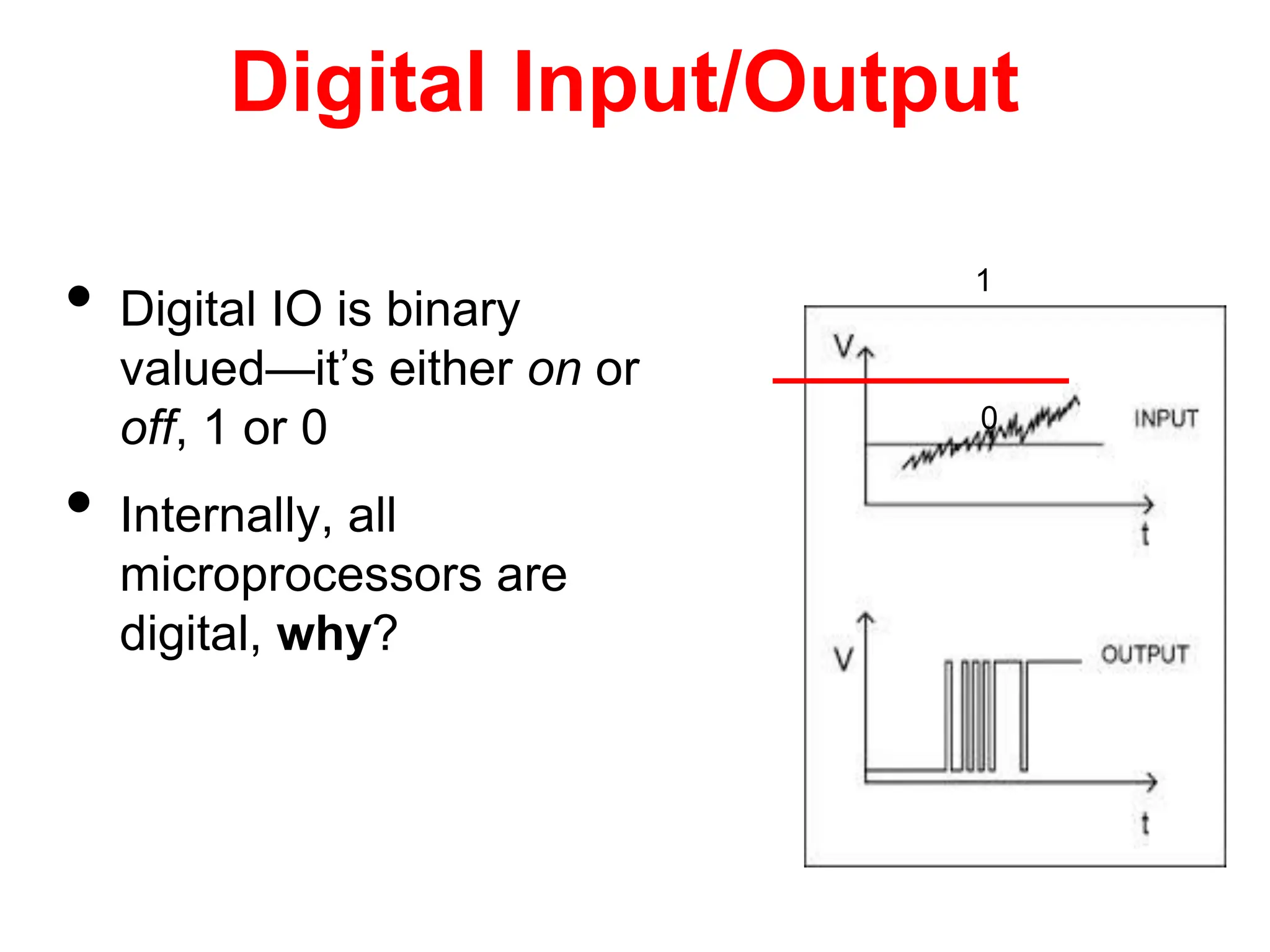
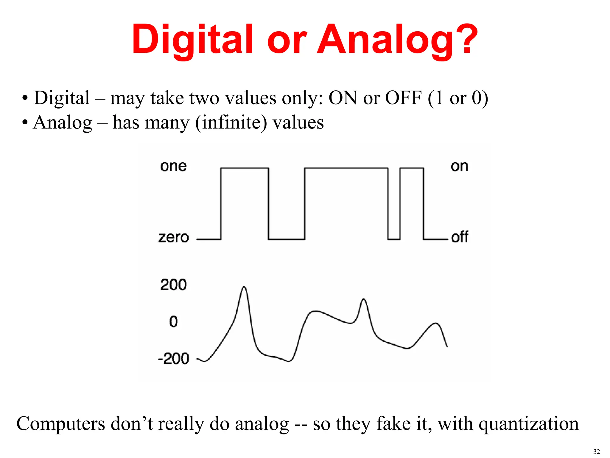
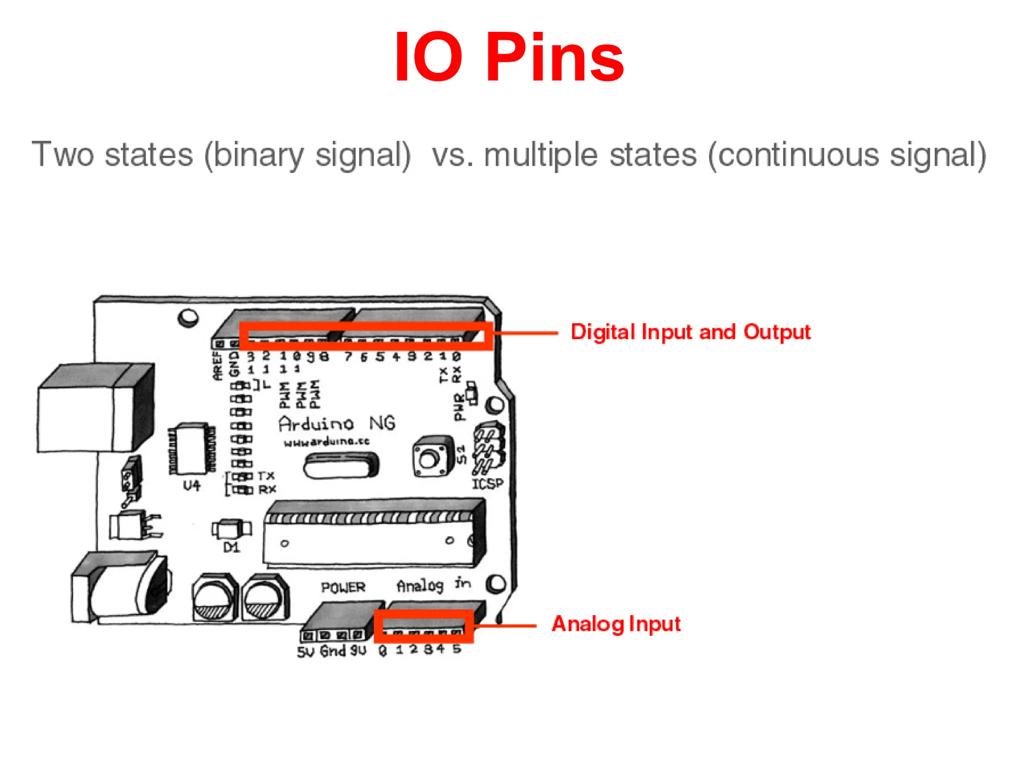
Lecture 3
Architecture of Arduino
development board
 http://www.arduino.cc/ 1
What do you need to start working
with Arduino?
1.Arduino board
2.USB cable
3.Computer with USB interface
4.USB driver and Arduino application
to be downloaded from
(http://arduino.cc/en/Main/Software)
2
 The Arduino is a programmable hardware board that runs
an 8-bit /16 Mhz microcontroller with a special bootloader
that allows users to upload programs to the icrocontroller.
 It has digital input pins for input from switches and
output to Actuators (LEDS or electrical motors)
 It also has analog pins to accept inputs from voltage-
based sensors.
 Arduino can be used to develop stand-alone interactive
objects or can be connected to software on your computer
3
What is Arduino?/ Open Source
 Open Source Hardware
The Arduino system is open source - all hardware (made by Arduino
distributors) has the schematics and PCB layouts available online.
 Open Source Bootloader
The bootloader is what runs on the chip before the program is run. It
boots the chip and executes the program.
 Open Source Development Kit
The development kit - what you use to program an Arduino board - is
also available online. It is free, open-source.
.
4
Arduino Terminology
• I/O Board - The I/O Board is the "brain" of the
operation (main microcontroller you program it
from your computer.
• Shield - A Shield is a device that plugs into an
I/O Board. These extend the capabilities of the
I/O Board.
• Sketch - A Sketch is a program written for the
board and shields.
5
Arduino Terminology
Sensor - components (Gas, etc.)
Modules - serial data (GPS module, etc.)
pin – an input or output connected to something.
Digital – value is either HIGH or LOW.
Analog – value ranges, usually from 0-255.
Arduino Types
 Many different versions
 Number of input/output channels
 Form factor
 Processor
 Leonardo
 Due
 Micro/Nano
 LilyPad
 Esplora
 Uno/number one
Leonardo
 Compared to the Uno, a slight upgrade.
 Built in USB compatibility
 Presents to PC as a mouse or keyboard
Due
 Much faster processor, many more pins
 Operates on 3.3 volts
 Similar to the Mega
Micro/ Nano
Arduino Nano
Arduino Nano is a surface mount breadboard
embedded version with integrated USB. It is a
smallest, complete, and breadboard friendly. It has
everything that Diecimila has (electrically) with
more analog input pins and onboard +5V AREF
jumper.
LilyPad
LilyPad Arduino
The LilyPad Arduino is a microcontroller board
designed for wearables and e-textiles. It can be
sewn to fabric and similarly mounted power
supplies, sensors and actuators with conductive
thread
.
Esplora
 Game controller
 Includes joystick, four buttons, linear
potentiometer (slider), microphone, light sensor,
temperature sensor, three-axis accelerometer.
 Not the standard set of IO pins.
Uno
 The pins are in three groups:
 6 analog pins
 14 digital pins
 power
Shields
Shields connect to the I/O board to extend it's functionality.
Wireless Network Shield Color LCD Shield
Power Driver Shield
GPS Shield
15
Ethernet Shield
XBee Shield
Wifi Shield
More Shields…
Communication shields - XBee, Ethernet, and Wifi
16
Modules
Bluetooth Module
GPS Module
RFID Module
Temperature &
Humidity Sensor
Modules send serial data strings to the Arduino.
17
Sensors and Modules
Gas Sensor
Temp & Humidity
Flex Sensor
Fingerprint Scanner
Shields aren't the only way to extend an Arduino board - you
can hook sensors to it!
18
Photoresistor, infared, force sensitive resistor, Hall
effect, Piezo, tilt sensor..
Sensors
19
Arduino Board Overview
Microcontroller
chip
Power
pins
Digital input/output pins
Power LED
Reset button
Analog
Input
pins
Power connector
USB connector
USB chip
20
Arduino Components
21
Nano
22
Nano
23
Arduino Board Schematic
24
Components of the Arduino
• ATMega168/328
• 16MHz crystal/filtering
capacitors
• Onboard power
regulators
• FTDI USB <-> Serial
Chip
• Hardware
25
Necessary parts for any
circuit
• ATMega168/328
• The ‘brains’ of the
Arduino
• Program is loaded
onto the chip
• Runs main loop until
power is removed
• That’s it! All other
parts are optional!
26
Optional parts: Timing
• 16Mhz Crystal
• The ‘heartbeat’ of the
ATMega chip
• Speed of crystal
determines chip speed
• Possible to
over/underclock
depending on
application
• ATMega series has
onboard oscillator; less
precise
27
Power Supply
• 5 Volt and 3.3 Volt
Regulators
• Filtering capacitors
• Automatic switching
between external and
USB Power
• Leave it out if you
have a filtered 5 Volt
power supply
28
FTDI USB Chip
• Allows your Arduino
to communicate with
your computer over a
simple USB link
• Only necessary for
communicating with
USB
29
Hardware
• Circuit Board
• Headers
• USB port
• Sockets
30
Digital Input/Output
• Digital IO is binary
valued—it’s either on or
off, 1 or 0
• Internally, all
microprocessors are
digital, why?
1
0
Digital or Analog?
• Digital – may take two values only: ON or OFF (1 or 0)
• Analog – has many (infinite) values
Computers don’t really do analog -- so they fake it, with quantization
32
IO Pins
Arduino Digital I/0
pinMode(pin_no., dir)
Sets pin to either INPUT or OUTPUT
digitalRead(pin)
Reads HIGH or LOW from a pin
digitalWrite(pin, value)
Writes HIGH or LOW to a pin
Pin Used as an Output
• Turn on LED, which is connected
to pin Arduino pin 0 (PD0) (note
the resistor!)
• What should the data direction
be for pin 0 (PD0)?
• pinMode(0,OUTPUT);
• Turn on the LED
• digitalWrite(0,HIGH) ;
• Turn off the LED
• digitalWrite(0,LOW);
ATmega328
Arduino
pin 0
(PD0)
Pins as Inputs and Pull-up Resistors - 1
• Using a switch as a sensor
• Ex. Seat belt sensor
• Detect the switch state
• What should the data direction
be for Arduino pin 3 (PD3)?
• pinMode(3, INPUT);
• What will the voltage be on PD3
when the switch is closed?
• What will the voltage be on PD3
when the switch is open?
• Indeterminate!
ATmega328
Arduino
pin 3
(PD3)
Pins as Inputs and Pull-up Resistors - 2
• Switch as a sensor, cont.
• Make the voltage on the pin
determinate by turning on the pull-up
resistor for PD3
• Assuming PD3 is an input:
• digitalWrite(3,HIGH); turns
on the “pull-up” resistor
• pinMode(3,INPUT_PULLUP);
• What will the voltage on PD3 be
when the switch is open?
• VTG
• What will the voltage on PD3 be
when the switch is closed?
ATmega328
PD3
VTG= +5V
0
1
Pins as Inputs and Pull-up Resistors - 3
• Switch as a sensor, cont.
• To turn off the pull-up
resistor
• Assuming PD3 is an
input:
• digitalWrite(3,LOW); turns the
“pull-up” resistor off
ATmega328
PD3
VTG= +5V
0
1
Pins as Inputs and Pull-up Resistors - 4
• Possibility of ‘weak drive’
• Pin set as an input with a
pull-up resistor turned on
can source a small current
ATmega328
PD3
VTG= +5V
0
1
iweak
Pin Voltages
• Output pins can provide 40 mA of current
• HIGH or LOW (logic: 1 or 0)
• Voltages
• TTL
• 5 V (for HIGH)
• 0 V (for LOW)
• 3.3 V CMOS
• 3.3 V (for HIGH)
• 0 V (for LOW)
The power pins are as follows:
• Vin. The input voltage to the Arduino board when it's using an external power
source (as opposed to 5 volts from the USB connection or other regulated power
source). You can supply voltage through this pin, or, if supplying voltage via the
power jack, access it through this pin.
• 5V. The regulated power supply used to power the microcontroller and other
components on the board. This can come either from Vin via an on-board
regulator, or be supplied by USB or another regulated 5V supply.
• 3V3. A 3.3 volt supply generated by the on-board FTDI chip. Maximum current
draw is 50 mA.
• GND. Ground pins.
Power connector
USB connector
Vin
5V output
3V3 output
input voltage to the Arduino board
41

The document proceeds to explain the main components of an Arduino Uno board such as the power supply, USB port, microcontroller, analog and digital pins.

  • 1.
    Lecture 3 Architecture ofArduino development board  http://www.arduino.cc/ 1
  • 2.
    What do youneed to start working with Arduino? 1.Arduino board 2.USB cable 3.Computer with USB interface 4.USB driver and Arduino application to be downloaded from (http://arduino.cc/en/Main/Software) 2
  • 3.
     The Arduinois a programmable hardware board that runs an 8-bit /16 Mhz microcontroller with a special bootloader that allows users to upload programs to the icrocontroller.  It has digital input pins for input from switches and output to Actuators (LEDS or electrical motors)  It also has analog pins to accept inputs from voltage- based sensors.  Arduino can be used to develop stand-alone interactive objects or can be connected to software on your computer 3
  • 4.
    What is Arduino?/Open Source  Open Source Hardware The Arduino system is open source - all hardware (made by Arduino distributors) has the schematics and PCB layouts available online.  Open Source Bootloader The bootloader is what runs on the chip before the program is run. It boots the chip and executes the program.  Open Source Development Kit The development kit - what you use to program an Arduino board - is also available online. It is free, open-source. . 4
  • 5.
    Arduino Terminology • I/OBoard - The I/O Board is the "brain" of the operation (main microcontroller you program it from your computer. • Shield - A Shield is a device that plugs into an I/O Board. These extend the capabilities of the I/O Board. • Sketch - A Sketch is a program written for the board and shields. 5
  • 6.
    Arduino Terminology Sensor -components (Gas, etc.) Modules - serial data (GPS module, etc.) pin – an input or output connected to something. Digital – value is either HIGH or LOW. Analog – value ranges, usually from 0-255.
  • 7.
    Arduino Types  Manydifferent versions  Number of input/output channels  Form factor  Processor  Leonardo  Due  Micro/Nano  LilyPad  Esplora  Uno/number one
  • 8.
    Leonardo  Compared tothe Uno, a slight upgrade.  Built in USB compatibility  Presents to PC as a mouse or keyboard
  • 9.
    Due  Much fasterprocessor, many more pins  Operates on 3.3 volts  Similar to the Mega
  • 10.
    Micro/ Nano Arduino Nano ArduinoNano is a surface mount breadboard embedded version with integrated USB. It is a smallest, complete, and breadboard friendly. It has everything that Diecimila has (electrically) with more analog input pins and onboard +5V AREF jumper.
  • 11.
    LilyPad LilyPad Arduino The LilyPadArduino is a microcontroller board designed for wearables and e-textiles. It can be sewn to fabric and similarly mounted power supplies, sensors and actuators with conductive thread .
  • 12.
    Esplora  Game controller Includes joystick, four buttons, linear potentiometer (slider), microphone, light sensor, temperature sensor, three-axis accelerometer.  Not the standard set of IO pins.
  • 13.
    Uno  The pinsare in three groups:  6 analog pins  14 digital pins  power
  • 14.
    Shields Shields connect tothe I/O board to extend it's functionality. Wireless Network Shield Color LCD Shield Power Driver Shield GPS Shield 15
  • 15.
    Ethernet Shield XBee Shield WifiShield More Shields… Communication shields - XBee, Ethernet, and Wifi 16
  • 16.
    Modules Bluetooth Module GPS Module RFIDModule Temperature & Humidity Sensor Modules send serial data strings to the Arduino. 17
  • 17.
    Sensors and Modules GasSensor Temp & Humidity Flex Sensor Fingerprint Scanner Shields aren't the only way to extend an Arduino board - you can hook sensors to it! 18
  • 18.
    Photoresistor, infared, forcesensitive resistor, Hall effect, Piezo, tilt sensor.. Sensors 19
  • 19.
    Arduino Board Overview Microcontroller chip Power pins Digitalinput/output pins Power LED Reset button Analog Input pins Power connector USB connector USB chip 20
  • 20.
  • 21.
  • 22.
  • 23.
  • 24.
    Components of theArduino • ATMega168/328 • 16MHz crystal/filtering capacitors • Onboard power regulators • FTDI USB <-> Serial Chip • Hardware 25
  • 25.
    Necessary parts forany circuit • ATMega168/328 • The ‘brains’ of the Arduino • Program is loaded onto the chip • Runs main loop until power is removed • That’s it! All other parts are optional! 26
  • 26.
    Optional parts: Timing •16Mhz Crystal • The ‘heartbeat’ of the ATMega chip • Speed of crystal determines chip speed • Possible to over/underclock depending on application • ATMega series has onboard oscillator; less precise 27
  • 27.
    Power Supply • 5Volt and 3.3 Volt Regulators • Filtering capacitors • Automatic switching between external and USB Power • Leave it out if you have a filtered 5 Volt power supply 28
  • 28.
    FTDI USB Chip •Allows your Arduino to communicate with your computer over a simple USB link • Only necessary for communicating with USB 29
  • 29.
    Hardware • Circuit Board •Headers • USB port • Sockets 30
  • 30.
    Digital Input/Output • DigitalIO is binary valued—it’s either on or off, 1 or 0 • Internally, all microprocessors are digital, why? 1 0
  • 31.
    Digital or Analog? •Digital – may take two values only: ON or OFF (1 or 0) • Analog – has many (infinite) values Computers don’t really do analog -- so they fake it, with quantization 32
  • 32.
  • 33.
    Arduino Digital I/0 pinMode(pin_no.,dir) Sets pin to either INPUT or OUTPUT digitalRead(pin) Reads HIGH or LOW from a pin digitalWrite(pin, value) Writes HIGH or LOW to a pin
  • 34.
    Pin Used asan Output • Turn on LED, which is connected to pin Arduino pin 0 (PD0) (note the resistor!) • What should the data direction be for pin 0 (PD0)? • pinMode(0,OUTPUT); • Turn on the LED • digitalWrite(0,HIGH) ; • Turn off the LED • digitalWrite(0,LOW); ATmega328 Arduino pin 0 (PD0)
  • 35.
    Pins as Inputsand Pull-up Resistors - 1 • Using a switch as a sensor • Ex. Seat belt sensor • Detect the switch state • What should the data direction be for Arduino pin 3 (PD3)? • pinMode(3, INPUT); • What will the voltage be on PD3 when the switch is closed? • What will the voltage be on PD3 when the switch is open? • Indeterminate! ATmega328 Arduino pin 3 (PD3)
  • 36.
    Pins as Inputsand Pull-up Resistors - 2 • Switch as a sensor, cont. • Make the voltage on the pin determinate by turning on the pull-up resistor for PD3 • Assuming PD3 is an input: • digitalWrite(3,HIGH); turns on the “pull-up” resistor • pinMode(3,INPUT_PULLUP); • What will the voltage on PD3 be when the switch is open? • VTG • What will the voltage on PD3 be when the switch is closed? ATmega328 PD3 VTG= +5V 0 1
  • 37.
    Pins as Inputsand Pull-up Resistors - 3 • Switch as a sensor, cont. • To turn off the pull-up resistor • Assuming PD3 is an input: • digitalWrite(3,LOW); turns the “pull-up” resistor off ATmega328 PD3 VTG= +5V 0 1
  • 38.
    Pins as Inputsand Pull-up Resistors - 4 • Possibility of ‘weak drive’ • Pin set as an input with a pull-up resistor turned on can source a small current ATmega328 PD3 VTG= +5V 0 1 iweak
  • 39.
    Pin Voltages • Outputpins can provide 40 mA of current • HIGH or LOW (logic: 1 or 0) • Voltages • TTL • 5 V (for HIGH) • 0 V (for LOW) • 3.3 V CMOS • 3.3 V (for HIGH) • 0 V (for LOW)
  • 40.
    The power pinsare as follows: • Vin. The input voltage to the Arduino board when it's using an external power source (as opposed to 5 volts from the USB connection or other regulated power source). You can supply voltage through this pin, or, if supplying voltage via the power jack, access it through this pin. • 5V. The regulated power supply used to power the microcontroller and other components on the board. This can come either from Vin via an on-board regulator, or be supplied by USB or another regulated 5V supply. • 3V3. A 3.3 volt supply generated by the on-board FTDI chip. Maximum current draw is 50 mA. • GND. Ground pins. Power connector USB connector Vin 5V output 3V3 output input voltage to the Arduino board 41