Downloaded 11 times


![Standard for Certification - 2.7-1, April 2006
Page 16
DET NORSKE VERITAS
For aluminium:
Base material:
C = Rp0.2 but not to be taken greater than 0.7 × Rm
Weld and heat affected zone:
C = yield strength in the weld and heat affected zone
See Tables 3-4 and 3-5 for yield strength of the approved alu-
minium qualities.
Note:
The strength of aluminium alloys is considerably reduced in
welds and heat affected zones. The reduction depends on materi-
al properties, initial tempering and type of product (rolled, ex-
truded). Materials not listed in Tables 3-4 and 3-5 will be
considered in each case.
---e-n-d---of---N-o-t-e---
4.2.2 Load distribution
In these calculations, internal loads shall be assumed evenly
distributed on the offshore container floor. For tank containers,
other containers with permanently mounted heavy equipment
and for dedicated purpose containers, the actual distribution of
the internal load shall be used in the calculations.
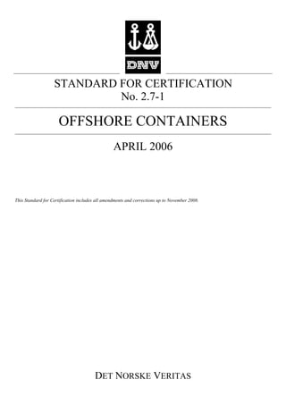
4.2.3 Lifting loads
4.2.3.1 Lifting with lifting set
The design load on the primary structure shall be taken as:
FL = 2.5 × R × g
To achieve this the internal load shall be taken as Fi = (2.5 x R-
T) × g,
Note:
Calculated deflections should be checked. Reference is made to
allowable deflections in prototype tests, see 4.6.3.2.
---e-n-d---of---N-o-t-e---
Pad eyes shall be designed for a total vertical load of:
The load Fp shall be considered as being evenly distributed be-
tween (n - 1) pad eyes where n is the actual number of pad eyes.
For calculation purposes n shall not exceed 4 or be less than 2.
To find resulting sling force on the pad eyes, the sling angle
must be taken into account. Hence, the resulting sling load
(RSL) on each pad eye will be:
where v is the angle between a sling leg and the vertical, as-
sumed to be 45° unless a smaller angle is specified.
Guidance note 1:
Containers without roof may have insufficient strength and stiff-
ness to pass the 2 point lifting test (4.6.3.3). In order to avoid
building prototypes that will not pass the test, the ability of an
open top container to withstand the load occurring in the 2-point
lifting test should be checked by a suitable calculation method.
In these calculations, the nominal yield stress, Re, of the material
should not be exceeded. The calculations do not replace proto-
type testing.
---e-n-d---of---G-u-i-d-a-n-c-e---n-o-t-e---
Guidance note 2:
Containers can be excessively flexible without having high cal-
culated stresses. These calculations should therefore also be used
to verify that the deflections (both maximum and relative) will be
acceptable.
---e-n-d---of---G-u-i-d-a-n-c-e---n-o-t-e---
Containers with only a single pad eye may be approved after
special consideration. The design load for such a pad eye shall
be taken as:
For requirements for lifting sets, see Section 8.
4.2.3.2 Lifting with fork lift truck
The mass of the lifting set, S, shall be taken into account when
calculating the strength of the fork pockets.
Guidance note:
If S is not known, an estimated mass of the lifting set may be used
in the calculations.
---e-n-d---of---G-u-i-d-a-n-c-e---n-o-t-e---
The design load on the primary structure shall be taken as:
FF = 1.6 × (R + S) × g
To achieve this, the internal load shall be taken as:
Fi = [1.6 × (R + S)-T] × g
Where fork pockets are only intended for empty handling of
the container, the design load shall be taken as FF = 1.6 × (T+S)
× g. For marking of containers with such pockets see 6.1.
4.2.4 Impact loads
Impact loads are dynamic loads of very short duration. Ideally,
dynamic calculations or tests should be carried out. However,
for most applications it is sufficient to carry out simplified stat-
ic calculations as outlined below to verify the local strength,
and to perform a vertical impact test (see 4.6.4) to verify the
container’s overall ability to withstand such loads.
When simplified calculations are used, and each beam is con-
sidered separately, due consideration shall be given to the sup-
port conditions for this beam.
4.2.4.1 Horizontal impact
The main frame structure shall be dimensioned to withstand a
local horizontal impact force acting at any point. This force
may act in any horizontal direction on the corner post. On all
other frame members in the sides the load may be considered
as acting at right angles to the side. Where relevant, the calcu-
lated stresses shall be combined with lifting stresses. However,
only stresses resulting from static lifting loads (R g) need to be
considered.
The following values shall be used for the static equivalents to
an impact load:
FHI = 0.25 × R × g for corner posts
FHI = 0.25 × R × g for side rails of the bottom structure
FHI = 0.15 × R × g for other frame members of the side struc-
ture, including the top rails
Calculated equivalent stresses shall not exceed:
σe = C
C is defined in section 4.2.1
Maximum calculated deflections with these loads shall not ex-
ceed:
where:
For corner posts and bottom side rails:
ln = the total length of the rail or post.
F R gp = × ×3
vn
gR
RSL
cos)1(
3
×−
××
=
F R gp = × ×5
y =
ln
250](https://image.slidesharecdn.com/tgstandard2-7-1-161023133720/85/Tg-standard2-7-1-16-320.jpg)


![Standard for Certification - 2.7-1, April 2006
Page 40
DET NORSKE VERITAS
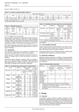
E.2 Chain Sling Dimensions
Based on EN 818-4
E.3 Wire Rope Sling Dimensions
Based on EN 13414-1
Table E-1 Working Load Limits for 1, 2 and 4 leg chain slings at different angles
Nominal size
of sling
Working Load Limits in tonnes
Singlelegslingand
forerunners
Four leg slings at Two leg slings at
(mm) 45° 40° 35° 30° 25° 45° 40° 35° 30° 25°
101) 3.15 [6.7] 7.24 7.7 8.2 8.6 [4.5] [4.8] [5.2] [5.5] [5.7]
13 5.30 11.2 12.2 13.0 13.8 14.4 7.5 8.1 8.7 9.2 9.6
16 8.00 17.0 18.4 19.7 20.8 21.8 11.3 12.3 13.1 13.9 14.5
18 10.0 21.2 23.0 24.6 26.0 27.2 14.1 15.3 16.4 17.3 18.1
19 11.2 23.8 25.7 27.5 29.1 30.5 15.8 17.2 18.3 19.4 20.3
20 12.5 26.5 28.7 30.7 32.5 34.0 17.7 19.2 20.5 21.7 22.7
22 15.0 31.8 34.5 36.9 39.0 40.8 21.2 23.0 24.6 26.0 27.2
23 16.0 33.9 36.8 39.3 41.6 43.5 22.6 24.5 26.2 27.7 29.0
25 20.0 42.4 46.0 49.1 52.0 54.4 28.3 30.6 32.8 34.6 36.3
26 21.2 45.0 48.7 52.1 55.1 57.6 30.0 32.5 34.7 36.7 38.4
28 25.0 53.0 57.5 61.4 65.0 68.0 35.4 38.3 41.0 43.3 45.3
32 31.5 66.8 72.4 77.4 81.8 85.6 44.5 48.3 51.6 54.6 57.1
36 40.0 84.9 91.9 98.3 103.9 108.8 56.6 61.3 65.5 69.3 72.5
40 50.0 106.1 114.9 122.9 129.9 135.9 70.7 76.6 81.9 86.6 90.6
1) Slings with WLL values below 7.0 may not be used on offshore containers, ref.Table 8-1 in Section 8.
Table E-2 Working Load Limits for 1, 2 and 4 leg wire rope slings at different angles
Fibre cored rope, grade 1770
Nominal size
of sling
Working Load Limits in tonnes
Single leg sling and
forerunners
Four leg slings at Two leg slings at
(mm) 45° 40° 35° 30° 25° 45° 40° 35° 30° 25°
181) 3.40 7.2 7.8 8.4 8.8 9.2 [4.8] [5.2] [5.6] [5.9] [6.2]
201) 4.35 9.2 10.0 10.7 11.3 11.8 [6.2] [6.7] 7.1 7.5 7.9
22 5.20 11.0 12.0 12.8 13.5 14.1 7.4 8.0 8.5 9.0 9.4
24 6.30 13.4 14.5 15.5 16.4 17.1 8.9 9.7 10.3 10.9 11.4
26 7.20 15.3 16.5 17.7 18.7 19.6 10.2 11.0 11.8 12.5 13.1
28 8.40 17.8 19.3 20.6 21.8 22.8 11.9 12.9 13.8 14.5 15.2
32 11.0 23.3 25.3 27.0 28.6 29.9 15.6 16.9 18.0 19.1 19.9
36 14.0 29.7 32.2 34.4 36.4 38.1 19.8 21.4 22.9 24.2 25.4
40 17.0 36.1 39.1 41.8 44.2 46.2 24.0 26.0 27.9 29.4 30.8
44 21.0 44.5 48.3 51.6 54.6 57.1 29.7 32.2 34.4 36.4 38.1
48 25.0 53.0 57.5 61.4 65.0 68.0 35.4 38.3 41.0 43.3 45.3
52 29.0 61.5 66.6 71.3 75.3 78.8 41.0 44.4 47.5 50.2 52.6
56 33.5 71.1 77.0 82.3 87.0 91.1 47.4 51.3 54.9 58.0 60.7
60 39.0 82.7 89.6 95.8 101.3 106.0 55.2 59.8 63.9 67.5 70.7
1) Ropes with WLL values below 7.0 may not be used on offshore containers, ref. Table 8-1 in Section 8.](https://image.slidesharecdn.com/tgstandard2-7-1-161023133720/85/Tg-standard2-7-1-40-320.jpg)
![DET NORSKE VERITAS
Standard for Certification - 2.7-1, April 2006
Page 41
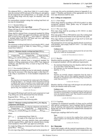
E.4 Wire Rope Sling Dimensions
Based on EN 13414-1
Table E-3 Working Load Limits for 1, 2 and 4 leg wire rope slings at different angles
Steel cored rope, grade 1770
Nominal size
of sling
Working Load Limits in tonnes
Single leg sling and
forerunners
Four leg slings at Two leg slings at
(mm) 45° 40° 35° 30° 25° 45° 40° 35° 30° 25°
181) 3.70 7.8 8.5 9.1 9.6 10.1 [5.2] [5.7] [6.1] [6.4] [6.7]
201) 4.60 9.8 10.6 11.3 12.0 12.5 [6.5] 7.0 7.5 8.0 8.3
22 5.65 12.0 13.0 13.9 14.7 15.4 8.0 8.7 9.3 9.8 10.2
24 6.70 14.2 15.4 16.5 17.4 18.2 9.5 10.3 11.0 11.6 12.1
26 7.80 16.5 17.9 19.2 20.3 21.2 11.0 12.0 12.8 13.5 14.1
28 9.00 19.1 20.7 22.1 23.4 24.5 12.7 13.8 14.7 15.6 16.3
32 11.8 25.0 27.1 29.0 30.7 32.1 16.7 18.1 19.3 20.4 21.4
36 15.0 31.8 34.5 36.9 39.0 40.8 21.2 23.0 24.6 26.0 27.2
40 18.5 39.2 42.5 45.5 48.1 50.3 26.2 28.3 30.3 32.0 33.5
44 22.5 47.7 51.7 55.3 58.5 61.2 31.8 34.5 36.9 39.0 40.8
48 26.0 55.2 59.8 63.9 67.5 70.7 36.8 39.8 42.6 45.0 47.1
52 31.5 66.8 72.4 77.4 81.8 85.6 44.5 48.3 51.6 54.6 57.1
56 36.0 76.4 82.7 88.5 93.5 97.9 50.9 55.2 59.0 62.4 65.3
60 42.0 89.1 96.5 103.2 109.1 114.2 59.4 64.3 68.8 72.7 76.1
1) Ropes with WLL values below 7.0 may not be used on offshore containers, ref. Table 8-1 in Section 8.](https://image.slidesharecdn.com/tgstandard2-7-1-161023133720/85/Tg-standard2-7-1-41-320.jpg)


This document outlines standards and certification procedures for offshore containers from Det Norske Veritas (DNV). It includes sections on materials, design, production, marking, lifting sets, periodic examination and testing. The key changes in the 2006 edition include more detailed requirements for lifting sets, new material standards for temperate climate use, and alignment with international standard EN 12079. Containers certified under this standard meet requirements of the IMO and EN 12079, and existing containers certified to previous versions generally comply with the new standard as well.


