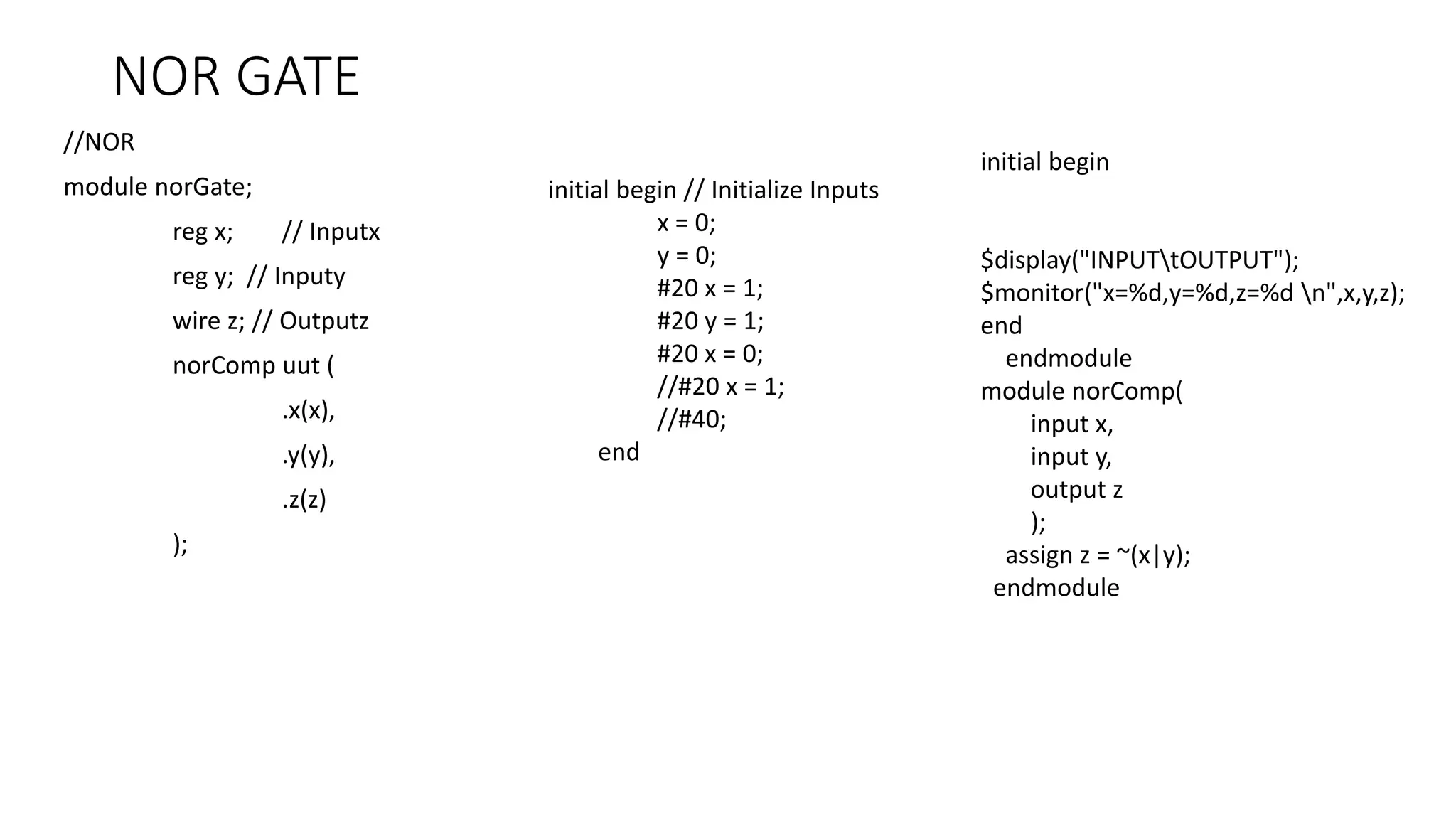
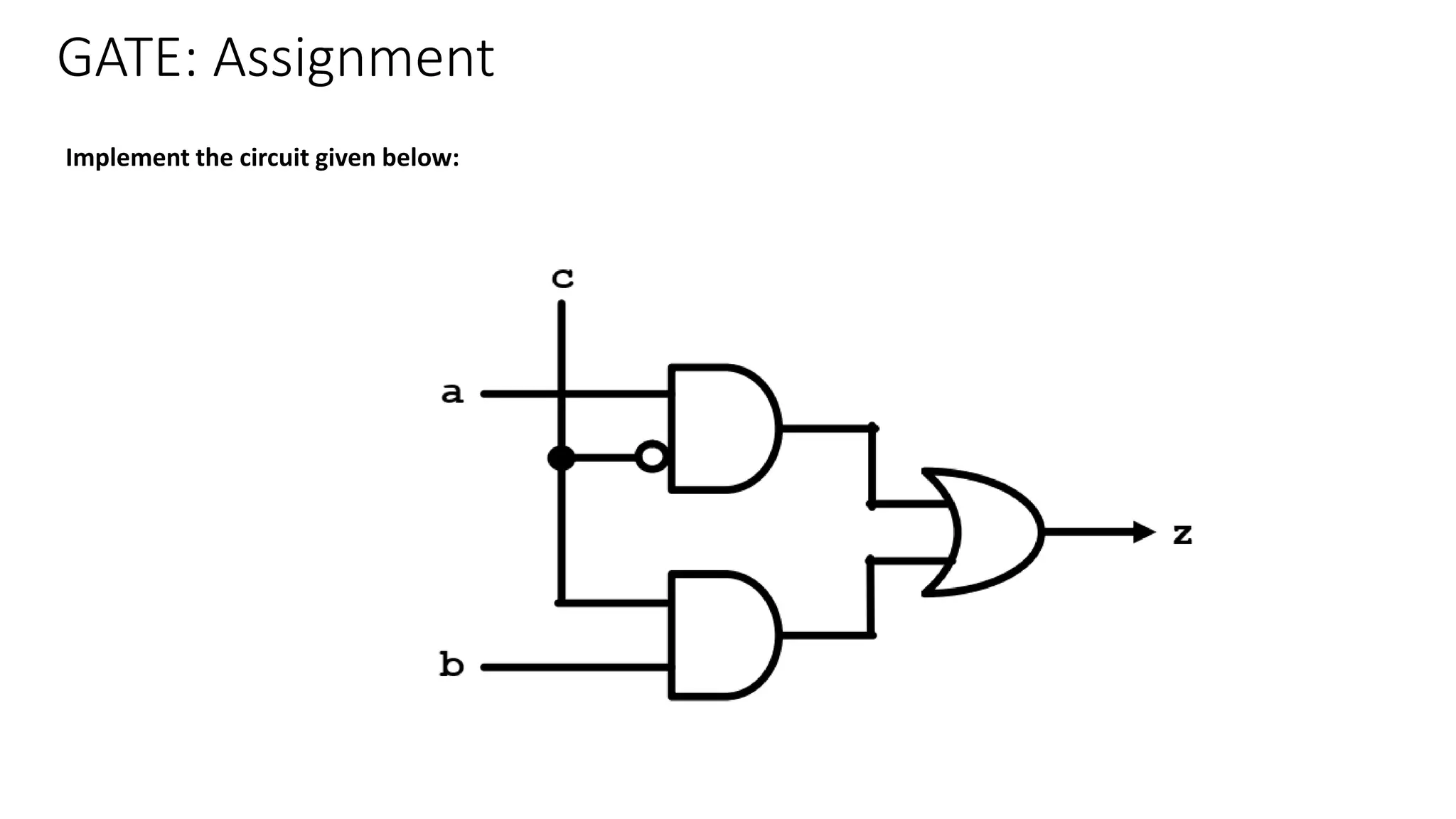
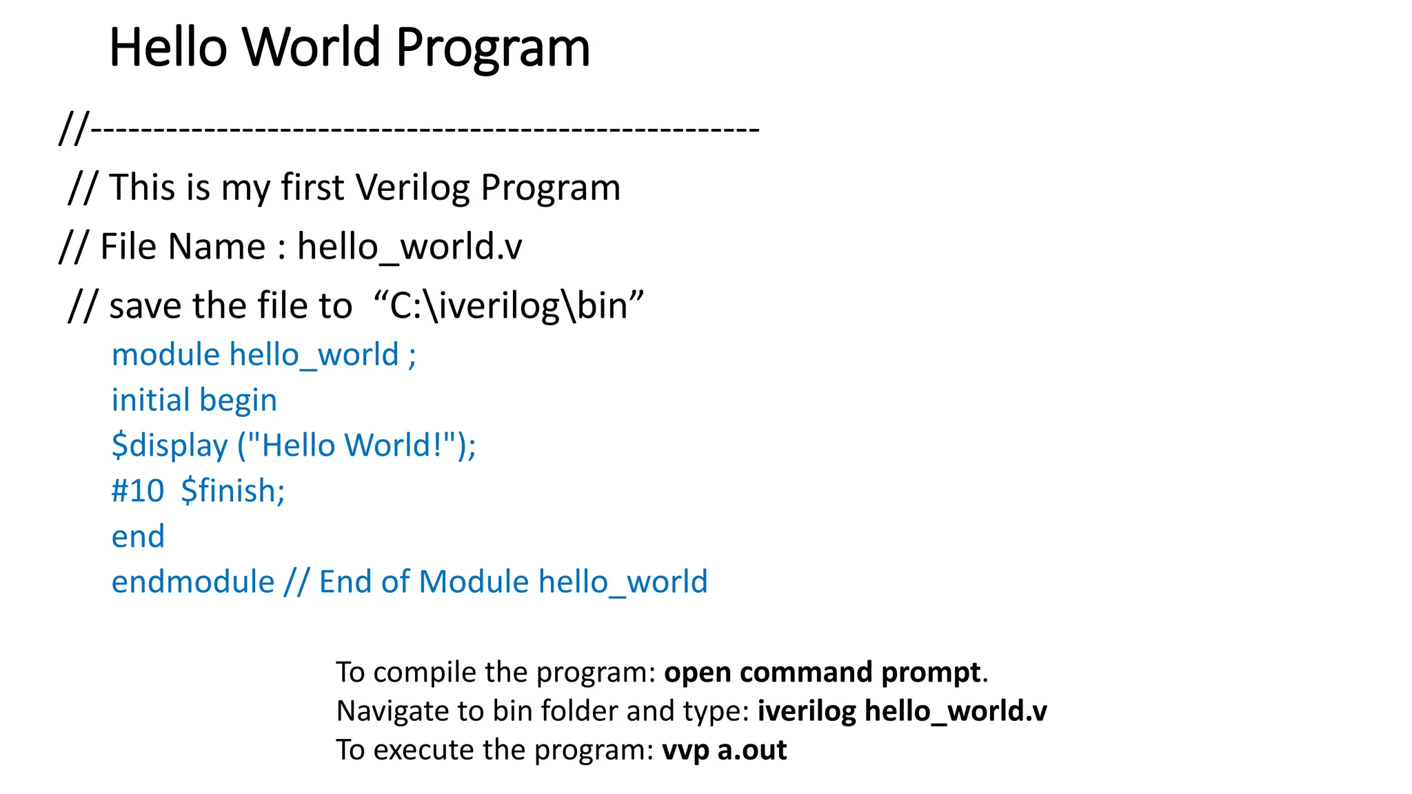
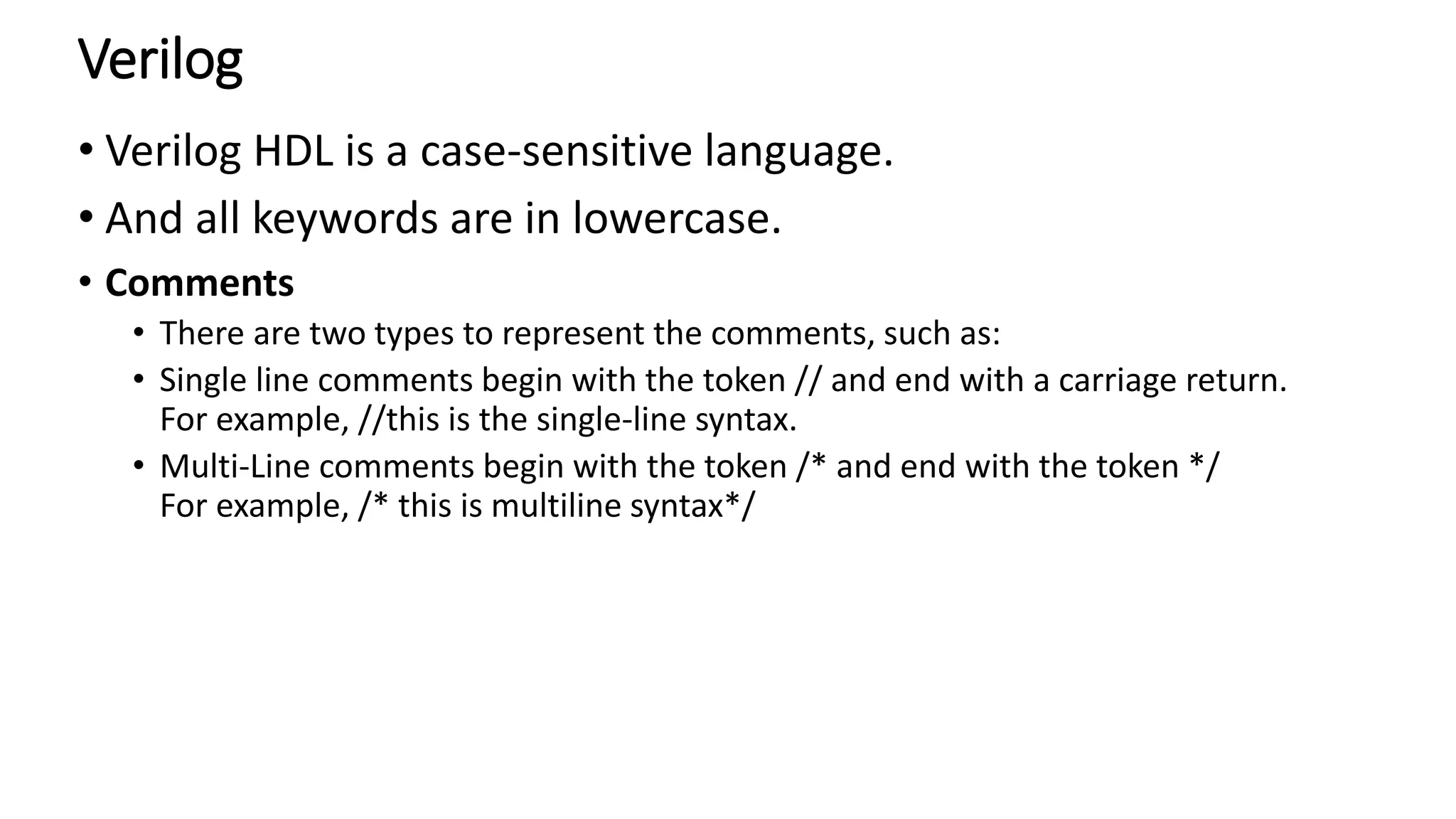
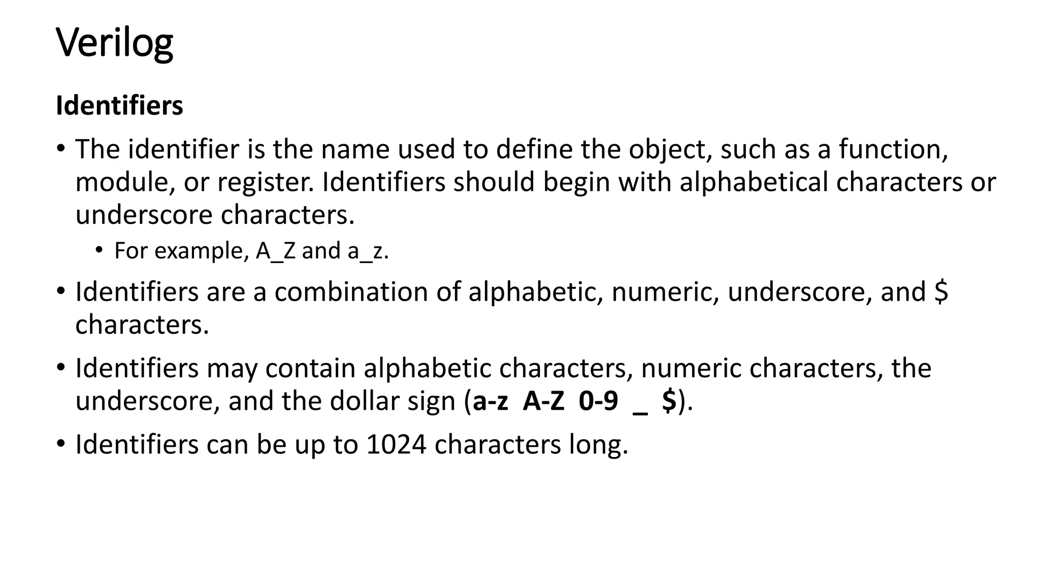
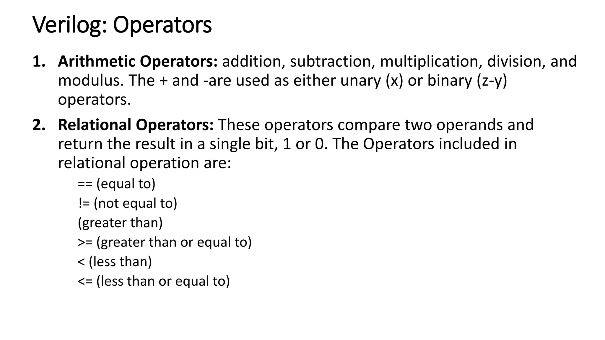
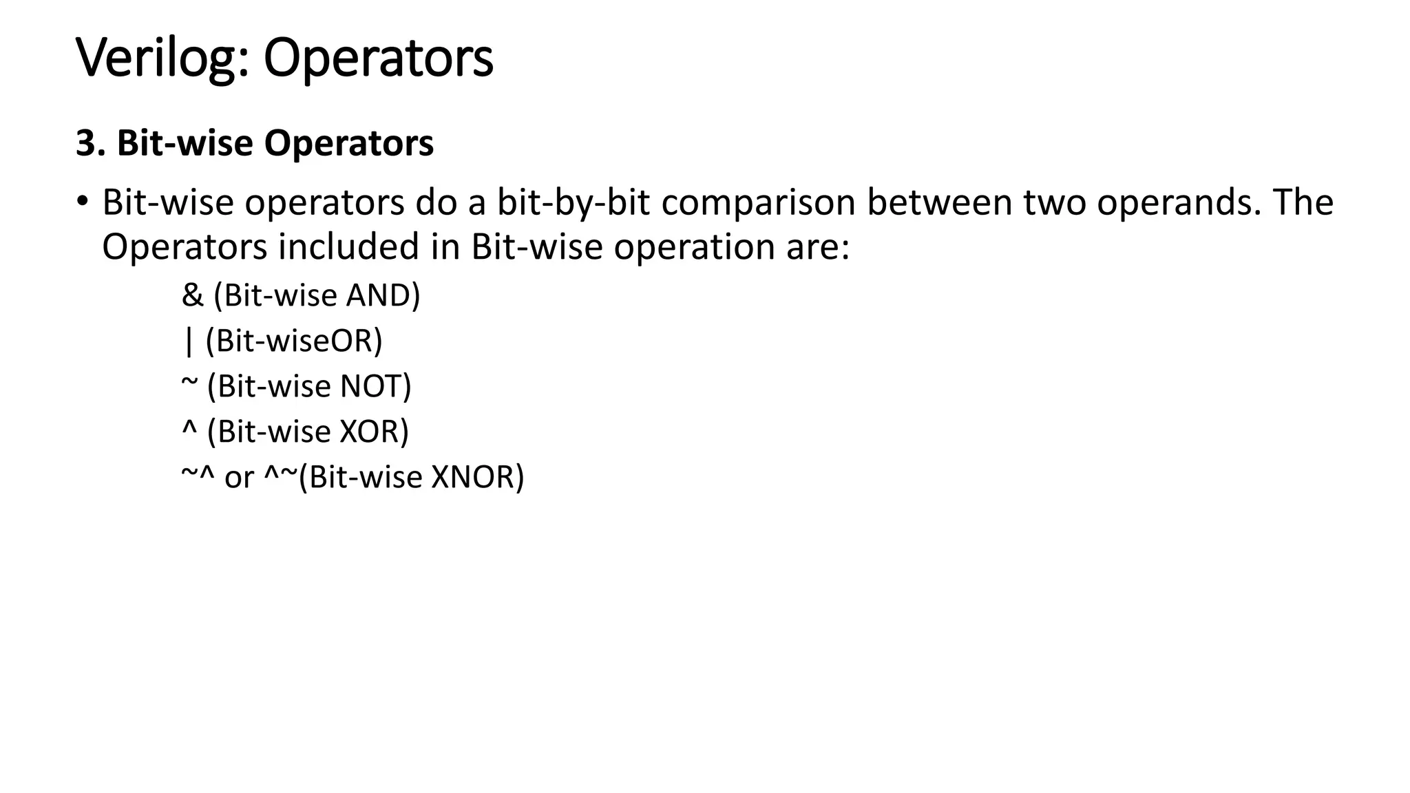
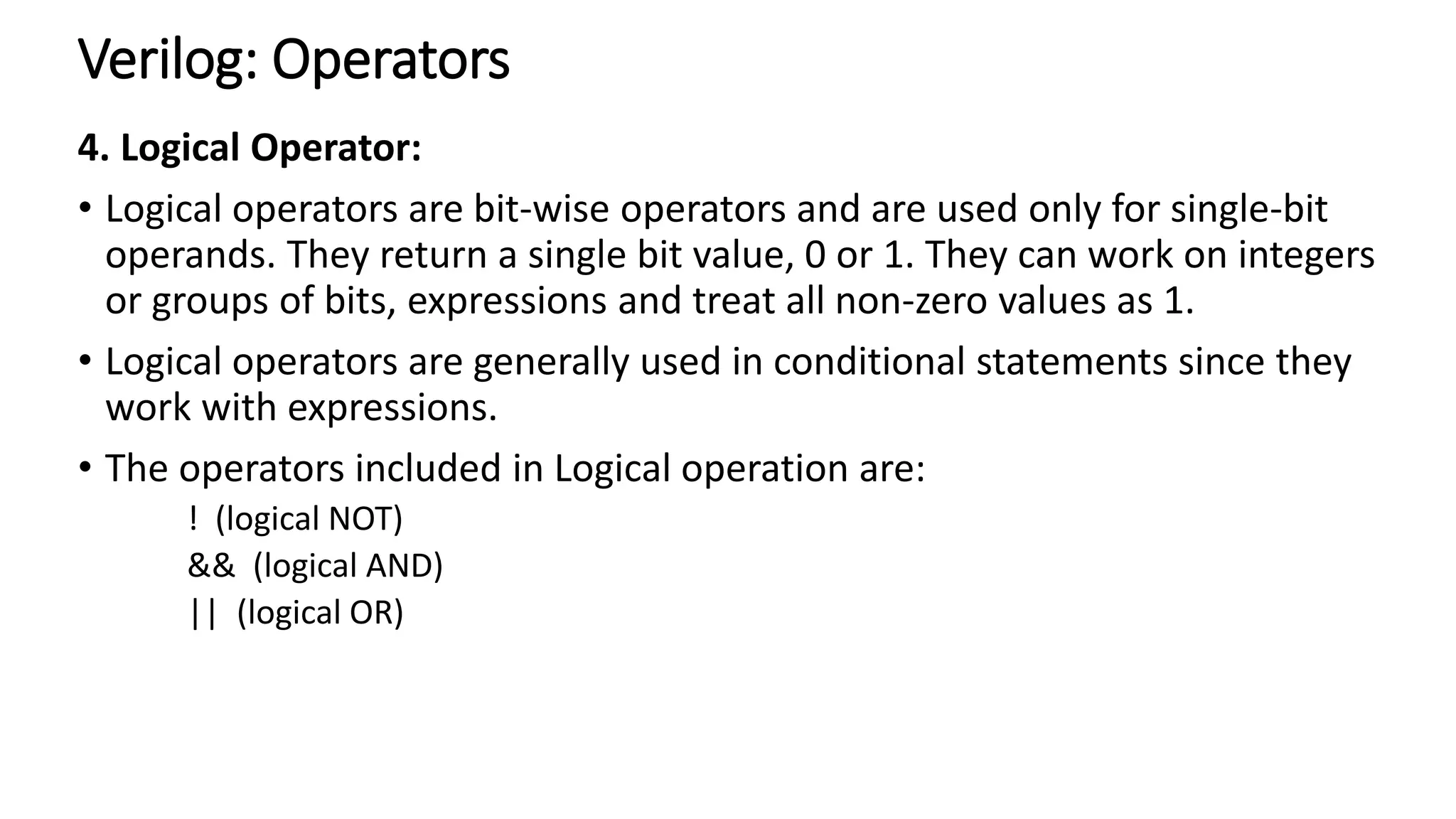
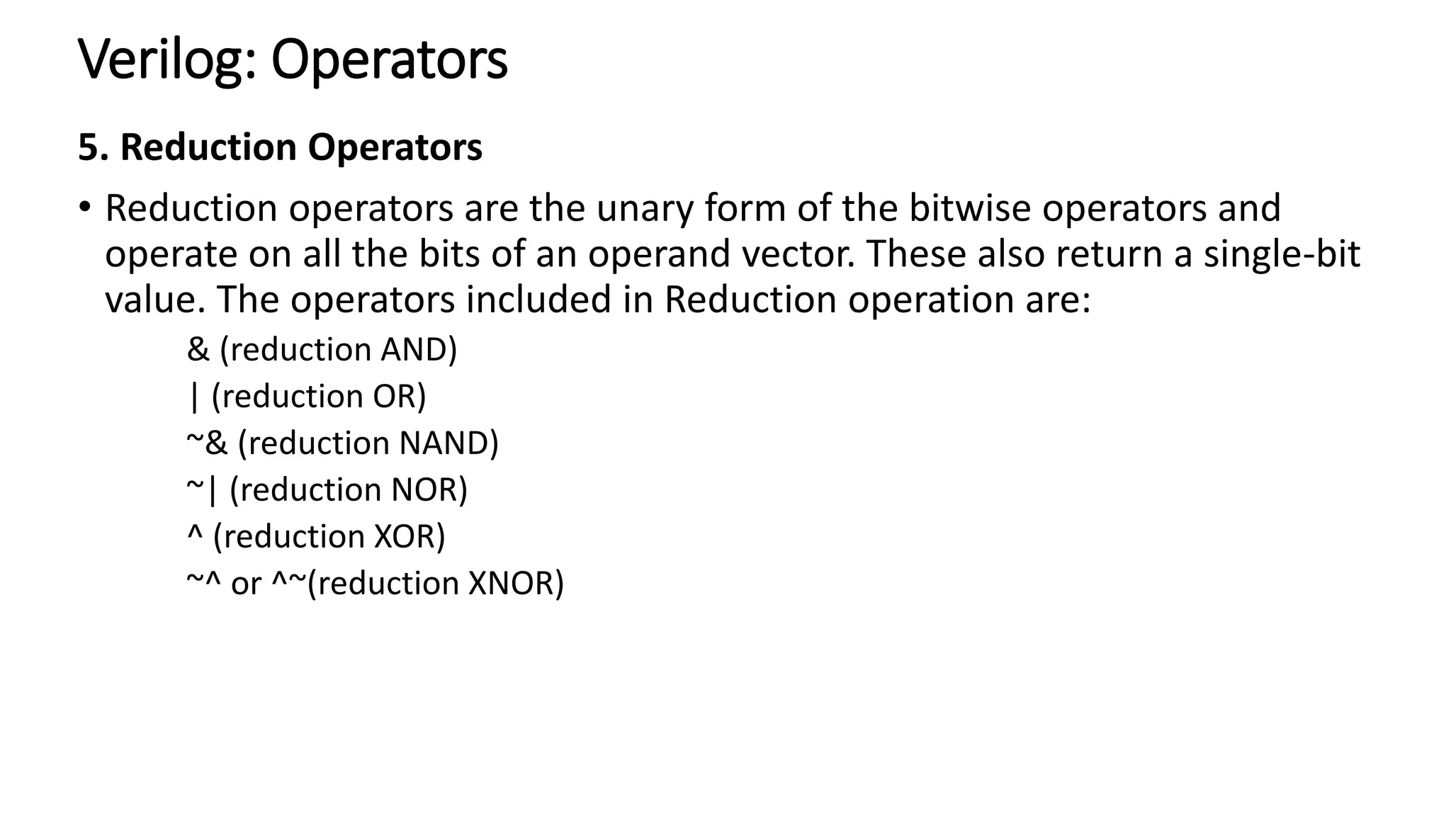
The document explains the use of Verilog, a hardware description language, for designing and verifying digital systems such as logic gates and microprocessors. It covers Verilog syntax, operators, data types, and practical code examples, including the implementation of logic gates and the handling of dumpfiles for debugging. Additionally, it highlights design methodologies like bottom-up and top-down approaches, emphasizing Verilog's flexibility and ease of use in electronic design.
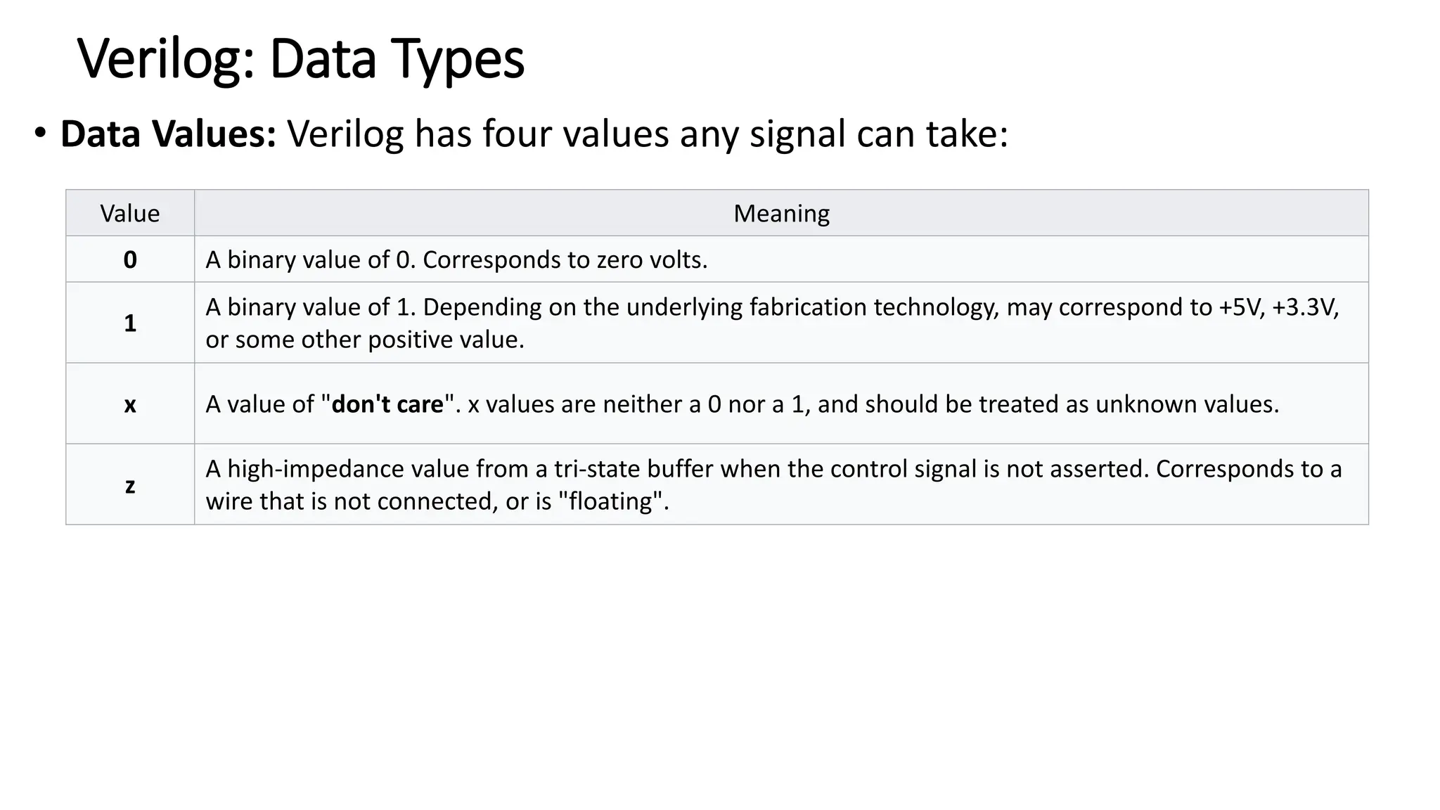
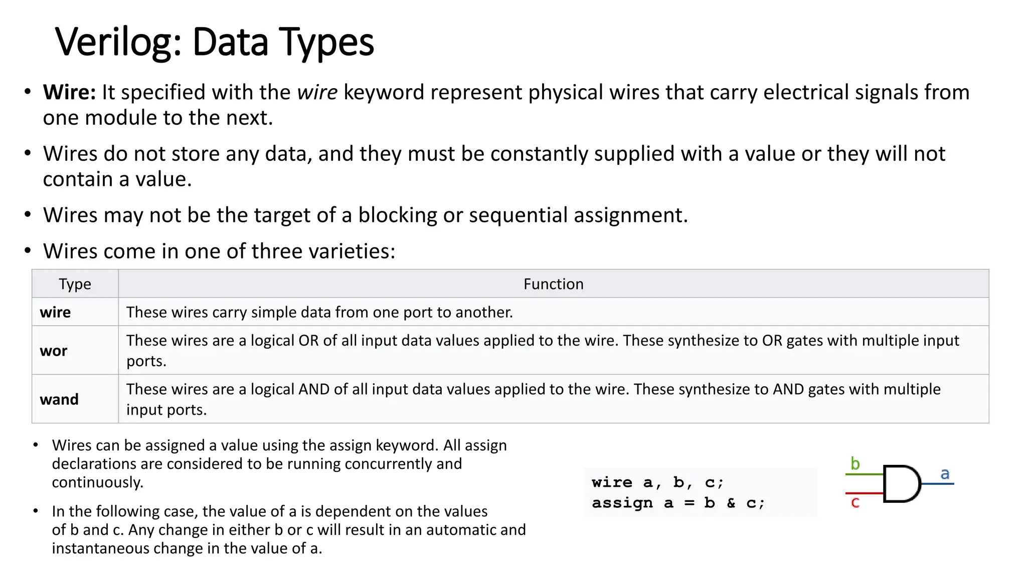
![Verilog: Data Types
reg:
• A register, denoted with the keyword reg is a memory storage location.
• with user-defined size
• Example:
reg a, b; //reg without size means 1-bit
reg [31:0] c; // a 32-bit register](https://image.slidesharecdn.com/experiment1-ucs704esd-240704101710-7e3b9d6d/75/Experiment-1-UCS-704_ESD-engineering-money-waste-13-2048.jpg)