Downloaded 132 times


![Color profile: Generic CMYK printer profile
Composite Default screen CertPrs8 / CCNA Cisco Certified Network Associate Study Guide / Deal / 222934-9 / Chapter 5
Basic Switch Configuration 17
Then type startup. Use CTRL-E to go to the end of the line and hit the
ENTER key to execute the command.
6. Log out of the router switch.
Use the exit command.
Now you should be more comfortable with the CLI of the IOS. The next section
shows you how to create a basic configuration on your 1900 and 2950 switch.
Basic Switch Configuration
This section covers the basics of accessing the 1900 and 2950 Catalyst switches, creating
a simple configuration on them, and using simple show commands.
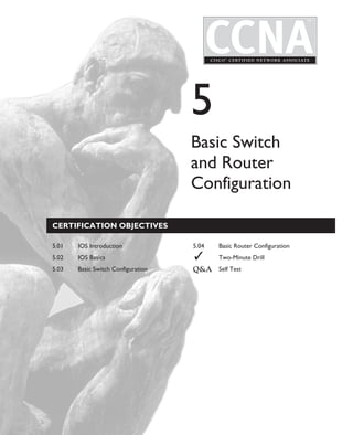
Accessing the CLI
Accessing the CLI on the 1900 is different from accessing the CLI on the 2950. With
the 1900, once the switch runs its hardware tests and loads the IOS, the IOS displays
this menu:
-------------------------------------------------
Catalyst 1900 Management Console
Copyright (c) Cisco Systems, Inc. 1993-1998
All rights reserved.
Enterprise Edition Software
Ethernet address: 00-C0-1D-81-A3-65
PCA Number: 73-3121-02
PCA Serial Number: FAA0252A7RT
Model Number: WS-C1924-EN
System Serial Number: FAA0304S0T5
Power Supple S/N: PHI025178F2
-------------------------------------------------
1 user(s) now active on Management Console.
User Interface Menu
[M] Menus
[K] Command Line
[I] IP Configuration
[P] Console Password
Enter Selection:
D:omhCertPrs8934-9ch05.vp
Monday, August 04, 2003 11:24:07 AM](https://image.slidesharecdn.com/ch05-120612072309-phpapp02/85/switch-and-router-configuration-17-320.jpg)


![Color profile: Generic CMYK printer profile
Composite Default screen CertPrs8 / CCNA Cisco Certified Network Associate Study Guide / Deal / 222934-9 / Chapter 5
Basic Switch Configuration 27
!
interface FastEthernet 0/27
!
line console
end
#
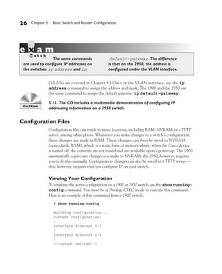
Saving Your Configuration
Configuration files are stored in NVRAM on both switches. When a switch boots up,
the IOS then loads this configuration from NVRAM and places it in RAM. On the 1900
switch, you do not have to do anything to save the active, or running, configuration—
within 30 seconds of executing a command, the 1900 automatically saves the configuration
to NVRAM (therefore, wait at least this length of time before turning off the 1900).
5.13. The CD includes a multimedia demonstration of configuring
on manipulating configuration files on a 2950 switch.
This is not true on the 2950 switch or IOS routers. Instead, you must execute the
copy running-config startup-config Privilege EXEC mode command to
save your changes. Upon executing this command, the 2950 or router takes the active
configuration in RAM and saves it to NVRAM. In this process, the old configuration
file in NVRAM is overwritten. Here is an example of using this command:
Switch# copy running-config startup-config
Destination filename [startup-config]?
Building configuration...
[OK]
Switch#
When executing this command, you are asked for a filename for the configuration
file—the default is “startup-config.” This is the filename the IOS looks for when booting
up. You can change the name for backup revisioning purposes (different versions of
the backed-up configuration), but make sure that your most current configuration
The 1900’s configuration save the configuration. The show
is automatically saved. On the 2950, running-config command displays
use the copy running-config the switch’s currently running configuration
startup-config command to in RAM.
D:omhCertPrs8934-9ch05.vp
Monday, August 04, 2003 11:24:09 AM](https://image.slidesharecdn.com/ch05-120612072309-phpapp02/85/switch-and-router-configuration-27-320.jpg)
![Color profile: Generic CMYK printer profile
Composite Default screen CertPrs8 / CCNA Cisco Certified Network Associate Study Guide / Deal / 222934-9 / Chapter 5
28 Chapter 5: Basic Switch and Router Configuration
is saved as “startup-config.” On the 2950, you can view the saved configuration in
NVRAM with the show startup-config Privilege EXEC mode command.
Verifying Switch Operation
Besides using the show running-config command to verify your switch’s
configuration, you can use many other commands. This section covers the show
interfaces, show ip, and show version commands. All of these commands
can be executed at either User or Privilege EXEC mode.
The show interfaces Command
To view the interfaces, status, and statistics for an interface, use the show interfaces
command:
> show interfaces [type slot_#/port_#]
If you don’t list a specific interface, all of the interfaces on the switch are listed.
Here is an example of this command on a 1900 switch:
> show interfaces ethernet 0/1
Ethernet 0/1 is Suspended-no-linkbeat
Hardware is Built-in 10Base-T
Address is 00E0.1EA1.a123
MTU 1500 bytes, BW 10000 Kbits
802.1d STP State: Blocking Forward Transitions: 2
Port monitoring: Disabled
Unknown unicast flooding: Disabled
Unregistered multicast flooding: Disabled
Description:
Duplex setting: Full duplex
Back pressure: Disabled
Receive Statistics Transmit Statistics
------------------------------- -------------------------------
Total good frames 0 Total frames 0
Total octets 0 Total octets 0
Broadcast/multicast frames 0 Broadcast/multicast frames 0
Broadcast/multicast octets 0 Broadcast/multicast octets 0
Good frames forwarded 0 Deferrals 0
Frames filtered 0 Single collisions 0
Runt frames 0 Multiple collisions 0
No buffer discards 0 Excessive collisions 0
Queue full discards 0
Errors: Errors:
FCS errors 0 Late collisions 0
D:omhCertPrs8934-9ch05.vp
Monday, August 04, 2003 11:24:09 AM](https://image.slidesharecdn.com/ch05-120612072309-phpapp02/85/switch-and-router-configuration-28-320.jpg)


![Color profile: Generic CMYK printer profile
Composite Default screen CertPrs8 / CCNA Cisco Certified Network Associate Study Guide / Deal / 222934-9 / Chapter 5
36 Chapter 5: Basic Switch and Router Configuration
file to load, the IOS then runs the System Configuration Dialog, commonly referred
to as Setup mode, which is a script that prompts you for configuration information.
The purpose of this script is to ask you questions that will allow you to set up a basic
configuration on your router: It is not intended as a full-functioning configuration tool.
In other words, the script doesn’t have the ability to perform all the router’s configuration
tasks. Instead, it is used by novices who are not that comfortable with the IOS CLI.
Once you become familiar with the CLI and many of the commands on the router,
you’ll probably never use this script again in your life.
Running the System Configuration Dialog
As was mentioned in the last paragraph, one way to access the System Configuration
Dialog is to boot up a router without a configuration in NVRAM. The second way is
to use the setup Privilege EXEC mode command, shown here:
Router# setup
--- System Configuration Dialog ---
Continue with configuration dialog? [yes/no]: y
At any point you may enter a question mark '?' for help.
Use ctrl-c to abort configuration dialog at any prompt.
Default settings are in square brackets '[]'.
Basic management setup configures only enough connectivity
for management of the system, extended setup will ask you
to configure each interface on the system
First, would you like to see the current interface summary? [yes]:
Interface IP-Address OK? Method Status Protocol
BRI0 unassigned YES unset administratively down down
BRI0:1 unassigned YES unset administratively down down
BRI0:2 unassigned YES unset administratively down down
Ethernet0 unassigned YES unset administratively down down
Serial0 unassigned YES unset administratively down down
Would you like to enter basic management setup? [yes/no]: n
Configuring global parameters:
Enter hostname [Router]:
The enable secret is a password used to protect access to
privileged EXEC and configuration modes. This password, after
entered, becomes encrypted in the configuration.
Enter enable secret: dealgroup1
The enable password is used when you do not specify an
enable secret password, with some older software versions,
D:omhCertPrs8934-9ch05.vp
Monday, August 04, 2003 11:24:11 AM](https://image.slidesharecdn.com/ch05-120612072309-phpapp02/85/switch-and-router-configuration-36-320.jpg)
![Color profile: Generic CMYK printer profile
Composite Default screen CertPrs8 / CCNA Cisco Certified Network Associate Study Guide / Deal / 222934-9 / Chapter 5
Basic Router Configuration 37
and some boot images.
Enter enable password: dealgroup2
The virtual terminal password is used to protect
access to the router over a network interface.
Enter virtual terminal password: cisco
Configure SNMP Network Management? [no]:
Configure LAT? [yes]: n
Configure AppleTalk? [no]:
Configure DECnet? [no]:
Configure IP? [yes]:
Configure IGRP routing? [yes]: n
Configure RIP routing? [no]:
<--output omitted-->
BRI interface needs isdn switch-type to be configured
Valid switch types are :
[0] none..........Only if you don't want to
configure BRI.
[1] basic-1tr6....1TR6 switch type for Germany
[2] basic-5ess....AT&T 5ESS switch type for the
US/Canada
[3] basic-dms100..Northern DMS-100 switch type
<--output omitted-->
Choose ISDN BRI Switch Type [2]:
Configuring interface parameters:
Do you want to configure BRI0 (BRI d-channel) interface? [no]:
Do you want to configure Ethernet0 interface? [no]: y
Configure IP on this interface? [no]: y
IP address for this interface: 172.16.1.1
Subnet mask for this interface [255.255.0.0] : 255.255.255.0
Class B network is 172.16.0.0, 24 subnet bits; mask is /24
Do you want to configure Serial0 interface? [no]:
Do you want to configure BRI0 interface? [no]:
The following configuration command script was created:
hostname Router
enable secret 5 $1$/CCk$4r7zDwDNeqkxFO.kJxC3G0
enable password dealgroup2
line vty 0 4
password cisco
no snmp-server
!
no appletalk routing
no decnet routing
ip routing
<--output omitted-->
end
[0] Go to the IOS command prompt without saving this config.
D:omhCertPrs8934-9ch05.vp
Monday, August 04, 2003 11:24:11 AM](https://image.slidesharecdn.com/ch05-120612072309-phpapp02/85/switch-and-router-configuration-37-320.jpg)
![Color profile: Generic CMYK printer profile
Composite Default screen CertPrs8 / CCNA Cisco Certified Network Associate Study Guide / Deal / 222934-9 / Chapter 5
38 Chapter 5: Basic Switch and Router Configuration
[1] Return back to the setup without saving this config.
[2] Save this configuration to nvram and exit.
Enter your selection [2]:
Information included in brackets ([]) are default values—if you just hit ENTER,
the value in the brackets is used. One problem with the script is that if you make
a mistake, there is no method of going back to the preceding question. Instead,
you can use the CTRL-C break sequence to abort the script. The following sections
break down the different components of the script.
The questions that the script asks you might be different from router to
router, depending on the hardware model and the software running on it.
Status and Global Configuration Information
At the beginning of the script, you are asked whether or not you want to continue. If
you answer “yes” or “y,” the script will continue; otherwise, if you answer “no” or “n,”
the script is aborted and you are returned to Privilege EXEC mode. The second thing
that you are asked is if you want to see the status of the router’s interfaces. If you answer
“y,” then you’ll see all of the interfaces on the router, the interfaces’ IP addresses, and
the status of the interfaces.
After the status information, you are taken into the actual configuration. The
first part of the configuration deals with all configuration information for the router
except for the interfaces, which is the second part. In this part of the configuration,
you are asked for things like the Privilege EXEC password, VTY (telnet) password,
which network protocols you want to activate, and other information.
Note that you are prompted for two Privilege EXEC passwords in the script:
enable secret and enable password. These passwords are the same as
discussed earlier in the 2950 configuration section. Even though you would
normally configure only one, the script requires you to enter both; it also requires
that both passwords be different. Just as with the 2950 configuration, the enable
secret password takes precedence over the enable password.
Protocol and Interface Configuration Information
After configuring the global information for the router, you are then lead through
questions about which interfaces you want to use and how they should be configured.
The script is smart enough to ask only configuration questions based on how you
answered the global questions. As an example, if you activate IP, the script asks you
D:omhCertPrs8934-9ch05.vp
Monday, August 04, 2003 11:24:11 AM](https://image.slidesharecdn.com/ch05-120612072309-phpapp02/85/switch-and-router-configuration-38-320.jpg)


![Color profile: Generic CMYK printer profile
Composite Default screen CertPrs8 / CCNA Cisco Certified Network Associate Study Guide / Deal / 222934-9 / Chapter 5
Basic Router Configuration 45
5.22. The CD includes a multimedia demonstration of using logging
synchronous on a Cisco router.
Configuring Router Interfaces
Accessing interfaces on IOS routers is the same as accessing interfaces on the 1900
and 2950 Catalyst switches. To access an interface and enter Interface Subconfiguration
mode, use the interface command:
Router(config)# interface type [slot_#/]port_#
Router(config-if)#
Unlike the Catalyst switches, which support only Ethernet-type interfaces, Cisco
routers support a wide variety of interfaces, including synchronous serial and async
serial, ISDN bri and pri, atm, fddi, tokenring, ethernet, fastethernet,
and gigabitethernet, as well as others. Of course, not every Cisco router supports
all types of interfaces. As an example, routers in the 800 series support only serial,
ISDN, and Ethernet.
After the type comes the location of the interface. Slot numbers begin with 0 and
port numbers begin with 0. Therefore, if you had an interface like ethernet 0/0,
this would be the first slot in the router, and the very first port; whereas, ethernet
1/1 would be in the second slot, and the port would be the second port.
Some routers do not support slots or modules, and therefore this is omitted—
instead you just list the port number. Examples of routers that do not have slots or
slot numbers are the 800, 1600, 1700, and 2500 routers. Here are some examples
of interface names where the router lacks slots:
■ ethernet 0 or e0
■ serial 0 or s0
■ bri 0
For those routers that support slots, the 3600 and 7200 routers, for example, you
must specify the slot number, followed by a slash, and then the port number. Here
are some examples:
■ ethernet 0/0 or e0/0
■ serial 1/0 or s1/0
Remember that when listing the type and slot and port numbers, you can concatenate
these values as shown in these examples.
D:omhCertPrs8934-9ch05.vp
Monday, August 04, 2003 11:24:12 AM](https://image.slidesharecdn.com/ch05-120612072309-phpapp02/85/switch-and-router-configuration-45-320.jpg)
![Color profile: Generic CMYK printer profile
Composite Default screen CertPrs8 / CCNA Cisco Certified Network Associate Study Guide / Deal / 222934-9 / Chapter 5
46 Chapter 5: Basic Switch and Router Configuration
Including an Interface Description You can add a description to any interface
on a router, or for that matter a switch, by using the description command:
Router(config)# interface type [slot_#/]port_#
Router(config-if)# description interface_description
The description is a one-line description describing the device that the interface
is connected to, or whatever description you want to assign. This description appears
in the output of the show interfaces command.
Enabling and Disabling Interfaces Unlike Catalyst switches, Cisco router
interfaces are disabled by default. For each interface that you want to use, you must
go into the interface with the interface command and activate it with the no
shutdown command:
Router(config)# interface type [slot_#/]port_#
Router(config-if)# no shutdown
Whenever the interface changes status, the router prints an information message
on the screen. Here is an example of where an interface on a router is being activated:
Router(config)# interface fastethernet0
Router(config-if)# no shutdown
1w0d: %LINK-3-UPDOWN: Interface FastEthernet0, changed state to up
1w0d: %LINEPROTO-5-UPDOWN: Line protocol on Interface
FastEthernet0, changed state to up
Router(config-if)#
When copying and pasting in order to active the interface. This is
a configuration file into the router, and the a common problem when copying and
router interface is disabled with the shutdown pasting a configuration file from an old
command, your pasted configuration file router to a new router, where the interfaces
must contain the no shutdown command on the new router are disabled by default.
In this example, the first information line indicates that the physical layer is
activated. The second line indicates that the data link layer is enabled. If you want
to disable a router’s interface, enter Interface Subconfiguration mode for that particular
interface and execute the shutdown command.
D:omhCertPrs8934-9ch05.vp
Monday, August 04, 2003 11:24:12 AM](https://image.slidesharecdn.com/ch05-120612072309-phpapp02/85/switch-and-router-configuration-46-320.jpg)
![Color profile: Generic CMYK printer profile
Composite Default screen CertPrs8 / CCNA Cisco Certified Network Associate Study Guide / Deal / 222934-9 / Chapter 5
Basic Router Configuration 47
5.23. The CD includes a multimedia demonstration of enabling and disabling
interfaces on a Cisco router.
Configuring LAN Interfaces Some routers, like the 4000 series, support dual
Ethernet connectors for a single interface. With some of these routers, the IOS is
intelligent enough to figure out which connector is being used and handles the
configuration automatically. In other cases, though, you must tell the router which
connector the interface should use by configuring the media-type command on
the interface:
Router(config)# interface ethernet [slot_#/]port_#
Router(config-if)# media-type media_type
Router(config-if)# speed 10|100|auto
Router(config-if)# [no] half-duplex
Here are the media types that you can specify: aui, 10baset, 100baset,
and mii.
For 10/100 Ethernet ports that support auto-sensing, it is recommended that you
hard-code the speed and duplexing with the speed and half-duplex commands.
Setting the speed to auto has the interface auto-sense both the speed and the
duplexing. In order to hard-code the duplexing, you must first hard-code the speed
to 10 or 100. To set the port to full-duplex, use the no half-duplex command.
Configuring Serial Interfaces When connecting a serial cable to the serial
interface of the router, typically clocking is provided by an external device, such as
a modem or a CSU/DSU. The router is the DTE and the external device is the DCE,
where the DCE provides the clocking. This type of WAN connection is discussed
further in Chapter 15.
In some cases, however, you might connect two routers back-to-back using the
routers’ serial interfaces. For instance, if you are building your own lab to practice
CCNA commands, you’ll more than likely connect the routers back-to-back to reduce
equipment costs. In this situation, each router, by default, is a DTE. Since clocking
is required in order for the interface to be enabled, one of the two routers will have to
perform the function of an external DCE. This is accomplished by using the clock
rate Interface Subconfiguration mode command on the a serial interface:
Router(config)# interface serial [slot_#/]port_#
Router(config-if)# clock rate rate_in_bits_per_second
D:omhCertPrs8934-9ch05.vp
Monday, August 04, 2003 11:24:12 AM](https://image.slidesharecdn.com/ch05-120612072309-phpapp02/85/switch-and-router-configuration-47-320.jpg)
![Color profile: Generic CMYK printer profile
Composite Default screen CertPrs8 / CCNA Cisco Certified Network Associate Study Guide / Deal / 222934-9 / Chapter 5
48 Chapter 5: Basic Switch and Router Configuration
When entering the clock rate, you can’t just choose any arbitrary value. Use the
context-sensitive help to find out which clock rates your serial interface supports.
Here are some possible values: 1200, 2400,
4800, 9600, 19200, 38400, 56000, 72000,
125000, 148000, 500000, 800000,
Use the show controller 1000000, 1300000, 2000000, and 4000000.
command to determine DTE and DCE Please note that that you can’t choose an
connections. Use the clock rate command arbitrary router in the back-to-back connection
to configure the speed for DCE connections. to be DCE—this is based on how the two routers
are cabled. One end of the cable is physically the
DTE, and the other is the DCE. Some cables are
marked and some are not, depending on where you purchased them from. If you are
not sure which router has the DTE end of the cable and which one has the DCE
end, you can determine this with the show controller command:
Router> show controller serial [slot_#/]port_#
This is one of the few commands where you cannot concatenate the type and the
port number—you must separate them by a space. Here is an example of the use of
this command:
Router> show controller serial 0
HD unit 0, idb = 0x121C04, driver structure at 0x127078
buffer size 1524 HD unit 0, DTE V.35 serial cable attached
<--output omitted-->
Notice that the second line of this example holds two important pieces of
information: the connection type (DTE) and the type of cable (V.35). Here is
an example of an interface connected to the end of a DCE cable:
Router> show controller serial 0
HD unit 0, idb = 0x1BA16C, driver structure at 0x1C04E0
buffer size 1524 HD unit 0, V.35 DCE cable, clockrate 64000
<--output truncated-->
In this example, the clocking has already been configured: 64,000 bps (bits per
second).
5.24. The CD includes a multimedia demonstration of setting the clocking on
a serial interface on a Cisco router.
Configuring the Bandwidth Parameter All interfaces have a bandwidth
value assigned to them. This is used by certain routing protocols, such as IGRP,
D:omhCertPrs8934-9ch05.vp
Monday, August 04, 2003 11:24:13 AM](https://image.slidesharecdn.com/ch05-120612072309-phpapp02/85/switch-and-router-configuration-48-320.jpg)
![Color profile: Generic CMYK printer profile
Composite Default screen CertPrs8 / CCNA Cisco Certified Network Associate Study Guide / Deal / 222934-9 / Chapter 5
Basic Router Configuration 49
OSPF, and EIGRP, when making routing decisions. (Routing protocols are covered
in Chapters 9, 10, and 11.) For LAN-based interfaces, the speed of the interface
becomes the bandwidth value, where the bandwidth is measured in kilobits per second
(Kbps). However, on serial interfaces, the bandwidth defaults to 1,554 Kbps, or the
speed of a T1 link. This is true no matter what the physical clock rate is on the
interface (discussed in the preceding section). To change the bandwidth value for
an interface, use the bandwidth Interface Subconfiguration mode command:
Router(config)# interface serial [slot_#/]port_#
Router(config-if)# bandwidth rate_in_Kbps
As an example, a serial interface clocked at 56,000 bps should have its bandwidth
value changed to 56 Kbps, like this:
Router(config)# interface serial 0
Router(config-if)# bandwidth 56
Please note that the rate command does this. The bandwidth
bandwidth command does not change command affects only routing protocols
the clock rate on an interface: the clock that use bandwidth as a metric.
Configuring IP Addressing Information
You can use many commands on the router to set up your IP addressing information.
One of the most common is to assign an IP address to an interface; however, there are
many more commands, including the setup of DNS, determining how subnet masks
appear in the output of show commands, restricting directed broadcasts, and others.
The following sections cover these configurations.
Assigning IP Addresses Unlike the 1900 and 2950, which only need a single
IP address, routers need a unique IP address on each interface that will route IP traffic.
Actually, each interface from a router is a separate network or subnet, and therefore
you need to plan your IP addressing appropriately and assign a network number to each
router segment and then take an unused host address from the segment and configure
it on the interface of the router. IP addressing and its components is discussed in
Chapter 3.
Let’s look at a couple of examples of incorrectly and correctly assigning IP addresses
to a router’s interfaces. Figure 5-1 shows an invalid configuration example.
D:omhCertPrs8934-9ch05.vp
Monday, August 04, 2003 11:24:13 AM](https://image.slidesharecdn.com/ch05-120612072309-phpapp02/85/switch-and-router-configuration-49-320.jpg)
![Color profile: Generic CMYK printer profile
Composite Default screen CertPrs8 / CCNA Cisco Certified Network Associate Study Guide / Deal / 222934-9 / Chapter 5
50 Chapter 5: Basic Switch and Router Configuration
In this example, there is only one network number: 192.168.1.0/24. Notice that
each interface on the router has an address from this network number. Actually, if you
would try to configure this addressing scheme on a router, you would get an overlapping
address error and be prevented from completing the addressing configuration.
Each interface needs a unique host address, as is shown in Figure 5-2. Notice that
in this example, each interface has an address from a different network number when
compared to the other interfaces on the router. As to which host address you choose
for the router interface, this is up to personal preference. Many administrators either
use the first or last host address in the network number for the router’s interface, but
any valid, unused host address from that network number can be used.
As you have probably already guessed, configuring an IP address on a router requires
you to be in Interface Subconfiguration mode. Here is the syntax of this command:
Router(config)# interface type [slot_#/]port_#
Router(config-if)# ip address IP_address subnet_mask
This syntax, as you can see, is the same as configuring an IP address on the 2950
switch. You can verify your IP addressing configuration with the show interfaces
or show ip interfaces command, discussed later, in the section “Verifying a
Router’s Operation.”
Using the example in Figure 5-2, here would be the router’s IP addressing
configuration:
Router(config)# interface ethernet 0
Router(config-if)# ip address 192.168.1.1 255.255.255.0
Router(config-if)# no shutdown
Router(config-if)# exit
Router(config)# interface ethernet 1
Router(config-if)# ip address 192.168.2.1 255.255.255.0
Router(config-if)# no shutdown
<--output omitted-->
FIGURE 5-1
Invalid addressing
configuration
for a router
D:omhCertPrs8934-9ch05.vp
Monday, August 04, 2003 11:24:13 AM](https://image.slidesharecdn.com/ch05-120612072309-phpapp02/85/switch-and-router-configuration-50-320.jpg)

![Color profile: Generic CMYK printer profile
Composite Default screen CertPrs8 / CCNA Cisco Certified Network Associate Study Guide / Deal / 222934-9 / Chapter 5
52 Chapter 5: Basic Switch and Router Configuration
If you want to reenable this function, use the following Interface Subconfiguration mode
command:
Router(config)# interface type [slot_#/]port_#
Router(config-if)# ip directed-broadcast
If you want to disable directed broadcasts again, just preface the preceding command
with the no parameter. You can verify your directed broadcast configuration with
the show ip interfaces command, discussed later, in the section “Verifying
a Router’s Operation.”
IP Subnet Mask Display Configuration Whenever you use many show
commands on your router and IP addresses are displayed, the default display format
for subnet masks is dotted-decimal. You can change the display format of subnet masks
with the following command:
Router# term ip netmask-format bit-count|decimal|hexadecimal
To begin with, execution of this command is not done from Configuration mode.
Therefore, this change takes effect only for your current login session—as soon as
you log out and log back in again, the default is to display the masking information
in the dotted-decimal format. Here are your display options:
■ bit-count Example: 192.168.1.0/24
■ decimal Example: 192.168.1.0 255.255.255.0 (default format)
■ hexadecimal Example: 192.168.1.0 0xFFFFFF00
Of course, you might get tired of continually retyping this command every time
you log in. Therefore, you can configure a default behavior that can be saved by the
router and will be the same every time that you log into the router. This is done from
Line Subconfiguration mode:
Router(config)# line line_type line_#
Router(config-line)# ip netmask-format bit-count|decimal|hexadecimal
Note that you will need to execute this command on each line from which you
access your router, as the following configuration shows:
Router(config)# line console 0
Router(config-line)# ip netmask-format bit-count
Router(config-line)# exit
Router(config)# line vty 0 4
Router(config-line)# ip netmask-format bit-count
D:omhCertPrs8934-9ch05.vp
Monday, August 04, 2003 11:24:14 AM](https://image.slidesharecdn.com/ch05-120612072309-phpapp02/85/switch-and-router-configuration-52-320.jpg)
![Color profile: Generic CMYK printer profile
Composite Default screen CertPrs8 / CCNA Cisco Certified Network Associate Study Guide / Deal / 222934-9 / Chapter 5
Basic Router Configuration 53
To verify your configuration, use the show interfaces or show ip
interfaces command to verify that the subnet mask is displaying correctly.
These commands are discussed later, in the section “Verifying a Router’s Operation.”
5.26. The CD includes a multimedia demonstration of changing the subnet
mask display on a Cisco router.
Static Host Configuration As you are well aware, in the IP world, we typically
don’t type in the IP address to reach a destination. For example, if you want to reach
Cisco’s site, in your web browser address bar, you type www.cisco.com or http://
www.cisco.com. Your web browser then resolves the host and domain names to an
IP address. The router also supports hostnames for certain operations, such as ping
and telnet, as is discussed in Chapter 6.
There are two basic ways to have your router resolve hostnames to IP addresses:
static and dynamic (using DNS). You can create a static resolution table by using
this command:
Router(config)# ip host name_of_host [TCP_port_#]
IP_address_of_host [2nd_IP_address...]
You must first specify the name of the remote host. Optionally, you can specify a
port number for the host—this defaults to 23 for telnet if you omit it. After this, you
can list up to eight IP addresses for this host. The router will try to reach the host
with the first address, and if that fails, try the second address, and so on and so forth.
Use the show hosts command to examine your static entries. This command is
covered later, in the section “Verifying a Router’s Operation.”
DNS Resolution Configuration If you have access to a DNS server or servers,
you can have your router use these to resolve names to IP addresses. This is configured
with the ip name-server command:
Router(config)# ip name-server IP_address_of_DNS_server
[2nd_server's_IP address ...]
You can list up to six DNS servers for the router to use with this command. Use the
show hosts command to examine your static and dynamic entries. This command
is covered later, in the section “Verifying a Router’s Operation.”
Many administrators don’t like using DNS to resolve names to addresses on routers,
because of one nuisance feature on the router: Whenever you type a nonexistent
D:omhCertPrs8934-9ch05.vp
Monday, August 04, 2003 11:24:14 AM](https://image.slidesharecdn.com/ch05-120612072309-phpapp02/85/switch-and-router-configuration-53-320.jpg)
![Color profile: Generic CMYK printer profile
Composite Default screen CertPrs8 / CCNA Cisco Certified Network Associate Study Guide / Deal / 222934-9 / Chapter 5
54 Chapter 5: Basic Switch and Router Configuration
command on the router, the router assumes you are trying to telnet to a device by
that name and tries to resolve it to an IP address. This is annoying because either you
have to wait for the DNS query to time out or you must execute the break sequence
(CTRL-SHIFT-6). You have another option, though, and that is to disable DNS lookups
on the router with the following command:
Router(config)# no ip domain-lookup
5.27. The CD includes a multimedia demonstration of using and disabling
name resolution on a Cisco router.
Verifying a Router’s Operation
Once you have configured your router, there are many, many commands that you have
available to use to examine and troubleshoot your configuration. This chapter covers some
of the basic show commands that you have at your disposal. Chapter 6 covers some more
commands, including ping, telnet, show cdp, and debug.
The show interfaces Command
One of the most common commands that you will use on a router is the show
interfaces command. This command allows you to see the status and configuration
of your interfaces, as well as some statistical information. Here is the syntax of this
command:
Router> show interfaces [type [slot_#/]port_#]
If you don’t specify a specific interface, the router displays all of its interfaces—
those enabled as well as those disabled. Here is an example of the output of this
command:
Router# show interfaces ethernet 0
Ethernet 0 is up, line protocol is up
Hardware is MCI Ethernet, address is 0000.0c00.1234
(bia 0000.0c00.1234)
Internet address is 172.16.16.2, subnet mask is 255.255.255.252
MTU 1500 bytes, BW 10000 Kbit, DLY 100000 usec, rely 255/255,
load 1/255
Encapsulation ARPA, loopback not set, keepalive set (10 sec)
ARP type: ARPA, ARP Timeout 4:00:00
Last input 0:00:00, output 0:00:00, output hang never
Last clearing of "show interface" counters 0:00:00
Output queue 0/40, 0 drops; input queue 0/75, 0 drops
Five minute input rate 0 bits/sec, 0 packets/sec
Five minute output rate 4000 bits/sec, 8 packets/sec
D:omhCertPrs8934-9ch05.vp
Monday, August 04, 2003 11:24:14 AM](https://image.slidesharecdn.com/ch05-120612072309-phpapp02/85/switch-and-router-configuration-54-320.jpg)
![Color profile: Generic CMYK printer profile
Composite Default screen CertPrs8 / CCNA Cisco Certified Network Associate Study Guide / Deal / 222934-9 / Chapter 5
Basic Router Configuration 55
2240375 packets input, 887359872 bytes, 0 no buffer
Received 722137 broadcasts, 0 runts, 0 giants
0 input errors, 0 CRC, 0 frame, 0 overrun, 0 ignored, 0 abort
10137586 packets output, 897215078 bytes, 0 underruns
4 output errors, 1037 collisions, 3 interface resets,
0 restarts
The first line of output shows the status of the interface. This status was described
previously, in the section “Verifying Switch Operation.” The second line is the MAC
address of the Ethernet interface. The third line has the IP address and subnet mask
configured on the interface.
The fourth line has the MTU Ethernet frame
size as well as the routing protocol metrics.
(These metrics are discussed in more depth in
Make sure you understand Chapters 9, 10, and 11, which discuss routing
the output of the show interfaces protocols.) Notice the “BW” parameter in this
command, since this is a powerful layer-2 line. Referred to as the bandwidth of the link,
troubleshooting tool. this is used by some routing protocols, such as
IGRP, OSPF, and EIGRP, when making routing
decisions. For Ethernet, this is always 10,000 Kbps. You can change this value with
the bandwidth command, discussed previously, in the section “Configuring the
Bandwidth Parameter.” Table 5-6 explains some of the elements that you may see
with the show interfaces command. Please note that depending on the type
of interface, the information displayed in the show interfaces command may
be slightly different.
5.28. The CD includes a multimedia demonstration of using the show
interfaces command on a Cisco router.
The show ip interface Command
Another common command that you will use on a router is the show ip
interface command. This command enables you to see the IP configuration
of your router’s interfaces:
Router> show ip interface [type [slot_#/]port_#]
Here is an abbreviated output of the show ip interface command:
Router# show ip interface
Ethernet1 is up, line protocol is up
Internet address is 192.168.1.1/24
Broadcast address is 255.255.255.255
Address determined by setup command
D:omhCertPrs8934-9ch05.vp
Monday, August 04, 2003 11:24:14 AM](https://image.slidesharecdn.com/ch05-120612072309-phpapp02/85/switch-and-router-configuration-55-320.jpg)


![Color profile: Generic CMYK printer profile
Composite Default screen CertPrs8 / CCNA Cisco Certified Network Associate Study Guide / Deal / 222934-9 / Chapter 5
Basic Router Configuration 59
Be familiar with the output uptime, the amount of RAM, NVRAM, and
of the show version command, including flash, the type and number of interfaces,
what is displayed, like the IOS version, the and the configuration register value.
Router Configuration Files
Working with configuration files on a router is exactly the same as working on a 2950
switch. To view your running (active) configuration file, use the show running-
config command:
Router# show running-config
Building configuration...
Current configuration:
!
version 12.0
no service udp-small-servers
no service tcp-small-servers
!
hostname Router
<--output omitted-->
Notice the references to “Building configuration. . .” and “Current configuration”
in this example. Both of these refer to the configuration in RAM.
To save your configuration file from RAM to NVRAM, use the copy running-
config startup-config command:
Router# copy running-config startup-config
Destination filename [startup-config]?
Building configuration..
Router#
To see the configuration file stored in NVRAM, use this command:
Router# show startup-config
Using 4224 out of 65536 bytes
!
D:omhCertPrs8934-9ch05.vp
Monday, August 04, 2003 11:24:15 AM](https://image.slidesharecdn.com/ch05-120612072309-phpapp02/85/switch-and-router-configuration-59-320.jpg)


The document discusses the basics of configuring Cisco switches and routers, including: 1. The IOS provides the interface between the user and Cisco device hardware, enabling commands to configure and manage the device. The IOS supports features for connectivity, scalability, reliability, and security. 2. Devices have three modes - User EXEC for basic monitoring, Privilege EXEC for advanced commands, and Configuration mode for changing settings. The enable command moves between User EXEC and Privilege EXEC. 3. Commands can be abbreviated and autocompleted. Context-sensitive help provides information about commands. Basic configuration involves tasks like setting the device name.


