Download to read offline
![International Research Journal of Engineering and Technology (IRJET) e-ISSN: 2395-0056
Volume: 04 Issue: 10 | Oct -2017 www.irjet.net p-ISSN: 2395-0072
© 2017, IRJET | Impact Factor value: 6.171 | ISO 9001:2008 Certified Journal | Page 954
where shear wall cannot be arranged for from the
foundation level.
Considerable increase in columnandbeamforcesin
shear wall and in-plane discontinuity structures.
The time history analysis results infers that,
Reinforced concrete frame with in-plane
discontinuity structure displays enhanced
performance in decreasing the peak displacement
up to 40 storey, above 40 storey RC frame with
shear wall systems improved performanceinfalling
the peak displacements. Hereafter it can be
determined that, above 40 storey, in-plane
discontinuity structure will have a lesser amountof
stability compared to shear wall structures.
5. REFERENCES
[1]. Sarkar P, Prasad A Meher, Menon Devdas, “Vertical
geometric irregularity in stepped building frames ”,
,Engineering Structures 32, (2010) , page no.2175–2182.
[2]. Karavallis, Bazeos and Beskos, “Estimation of seismic
inelastic deformation demands in plane steel MRF with
vertical mass irregularities ”,Engineering Structures 30,
(2008), page no. 3265–3275.
[3]. ChintanapakdeeC.andChopra A.K.,“Seismic Responseof
Vertically Irregular Frames: Response History and Modal
Pushover Analyses”, Journal of Structural Engineering,
ASCE, Vol. 130, (2004), issue 8, page no. 1177-1185.
4]. Das, S. and Nau, J.M, “Seismic Design Aspects of Vertically
Irregular Reinforced Concrete Buildings”,Earthquake
Spectra, Vol. 19, (2003), No. 3, page no. 455-477.
[5].Fragiadakis, M., Vamvatsikos, D. and Papadrakakis, M,
“Evaluation of the Influence of Vertical Irregularities on the
Seismic Performance of a Nine-Storey Steel Frame”,
Earthquake Engineering & Structural Dynamics, Vol. 35,
(2006) ,No. 12, page no. 1489-1509.
[6].Ruiz, S.E. and Diederich, R, “The Mexico Earthquake of
September 19, 1985 – The Seismic PerformanceofBuildings
with Weak First Storey”, Earthquake Spectra, Vol. 5, (1989),
No. 1, page no. 89-102.](https://image.slidesharecdn.com/irjet-v4i10168-171128091708/75/Study-on-Dynamic-Behaviour-of-High-Riser-Dual-System-with-In-Plane-Discontinuity-in-Vertical-Elements-Resisting-Lateral-Loads-6-2048.jpg)

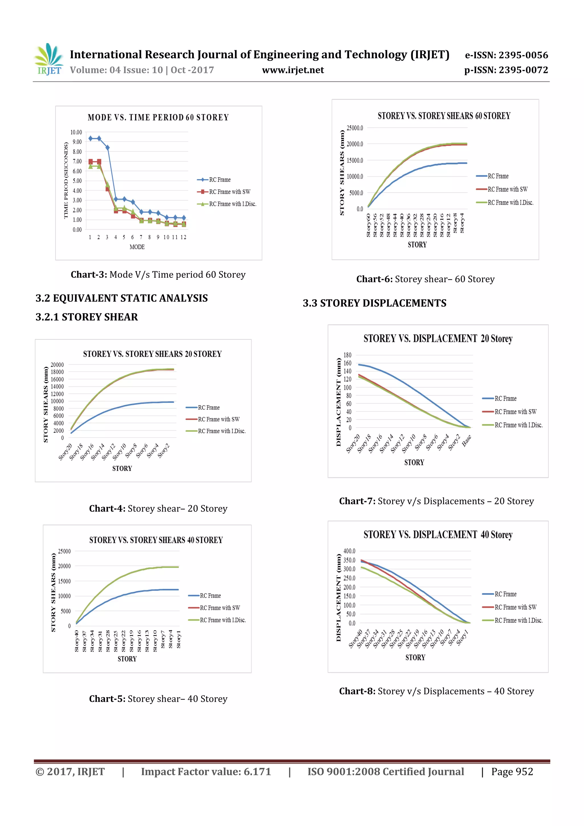
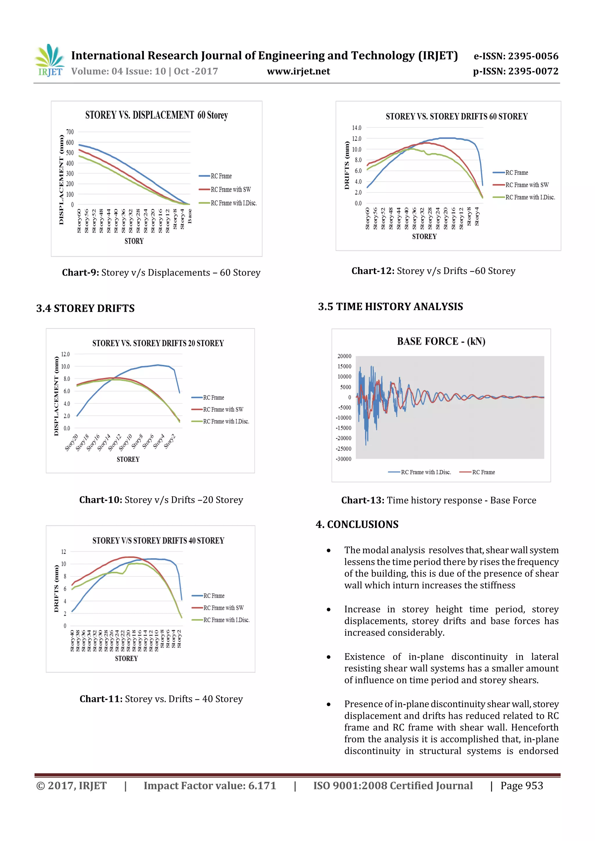
This study analyzes the dynamic behavior of high-rise dual systems with in-plane discontinuities in vertical elements resisting lateral loads. Three types of reinforced concrete structures are modeled - a regular frame, a frame with shear walls, and a frame with discontinuous shear walls. The structures are analyzed for heights of 20, 40, and 60 stories using equivalent static analysis and time history analysis in ETABS. Results show that shear walls reduce time period but increase stiffness. Taller structures have increased displacements, drifts, and base forces. Structures with discontinuous shear walls have smaller responses than regular frames, but perform worse than continuous shear wall structures above 40 stories.