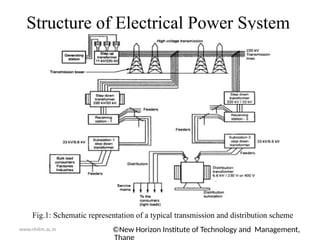
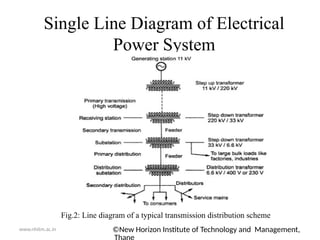
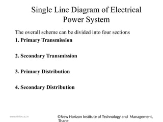
Program: Electrical Engineering
Academic Year: 2020-21
Class: SE Semester: III
Course Name: Electrical Power System-I
Course Code: EEC304
Presented By: Mr. Jayesh R. Dhuri
Designation: Assistant Professor
Department: Mechatronics Engineering
www.nhitm.ac.in ©New Horizon Institute of Technology and Management,
New Horizon Institute of Technology &
Management
©New Horizon Institute of Technology and Management,
Module No: I Module Title: Basic Structure of Power System
Part: I
Topics to be covered:
Basic Structure of Power System, Generation, Transmission and Distribution, Single Line
diagram of typical AC supply system
www.nhitm.ac.in
New Horizon Institute of Technology &
Management
www.nhitm.ac.in
©New Horizon Institute of Technology and Management,
Introduction
The energy is neither be created nor be destroyed but it can
be converted from one form to another. The generation of an
electrical energy is nothing but the conversion of various other
forms of energy into an electrical energy. the various energy
sources which used to generate electrical energy on the large scale
are steam obtained by burning coal, oil, natural gas, water stored in
dams, diesel, oil, nuclear etc.
the electrical power is generated in bulk at the generating
stations which are called power station. the power station are
located too far away from the town and cities where electrical
energy is demanded. hence there exits a large network of a
conductors between the power stations and the consumers. This
network is broadly classified into two parts.
1. Transmission 2. Distribution
©New Horizon Institute of Technology and Management,
www.nhitm.ac.in
The flow of electrical power from the generating station to
consumer is called an electrical power system.it consists of
following important components.
1. Generating Station
2. Transmission Network
3. Distribution Network
All these important networks are connected with the help
of conductors and various step up and step down
transformers.
Structure of Electrical Power System
©New Horizon Institute of Technology and Management,
www.nhitm.ac.in
Structure of Electrical Power System
Fig.1: Schematic representation of a typical transmission and distribution scheme
©New Horizon Institute of Technology and Management,
www.nhitm.ac.in
Structure of Electrical Power System
 a scheme shows generating station which is located too far
away from cities and towns.
 it is generating an electrical power at 11kV.
 with the help of transmission lines and the towers the power is
transmitted at very long distances.
 Design of the transmission lines based on the factors like
transmission voltage levels, constants like resistance, reactance
of the lines, line performance, interference with the neighboring
circuits
The transfer of power from receiving station to the substation is
with the help of conductors called feeders.
Components of Distribution
The distribution consists of following important components
1. Substation- transmission lines bring the power upto the substation at a
voltage level of 22kV or 33kV. At the substation the level is reduced to
3.3kV or 6.6kV. Then using feeders the power is given to local distribution
center.
2. Local Distribution Station- it consists of distribution transformers which
step down the voltage level from 3.3kV, 6.6kV to 400V or 230V. Then it is
distributed further using distributors. This is also called distribution
substation.
3. Feeders- These are the conductors which are of large current carrying
capacitor. The feeders connect the substation to the area where power is to
be finally distributed to the consumers.
4. Distributors- these are the conductors use to transfer power from
distribution centre to consumers.
5. Service Mains- These are the small cables between the distributors and
the actual consumer premises.
www.nhitm.ac.in
Components of Distribution
The interconnections of feeders, distributors and service mains is
shown below.
www.nhitm.ac.in
Fig.3: interconnections of feeders, distributors and service mains
©New Horizon Institute of Technology and Management,
www.nhitm.ac.in
Single Line Diagram of Electrical
Power System
Fig.2: Line diagram of a typical transmission distribution scheme
©New Horizon Institute of Technology and Management,
www.nhitm.ac.in
The overall scheme can be divided into four sections
1. Primary Transmission
2. Secondary Transmission
3. Primary Distribution
4. Secondary Distribution
Single Line Diagram of Electrical
Power System
©New Horizon Institute of Technology and Management,
www.nhitm.ac.in
The single line diagram is nothing but the simplified representation of
power system components with each other, with each component
represented by its symbol.
The standards symbols used for drawing single line diagram of a power
system are shown below.
Symbol used for Drawing Single Line Diagram
©New Horizon Institute of Technology and Management,
www.nhitm.ac.in
Symbol used for Drawing Single Line Diagram
©New Horizon Institute of Technology and Management,
www.nhitm.ac.in
Elements of Power System
The power system comprised of various elements such as generators, transformers
Transmission lines, bus bars, circuit breakers, isolators etc.
1. Generator- it is of synchronous type and is driven by turbine thus converting
mechanical Energy into electrical energy
2. Transformer- For stepping up or down the system voltage, power transformers are
used in the substations
3. Transmission Line- The transmission line forms the connecting link between
generating Substation and distribution systems.it carries the power generated by
generating stations and Make it available for distribution through distribution
network.
4. Bus Bars- Bus bars are the common electrical component that connect electrically
number of lines which are operating at the same voltage directly. these bars are
either copper or Aluminum.
5. Circuit Breakers- the circuit breaker are used to open or close a circuit under
normal and faulty conditions.
6. Isolators- in order to disconnect a part of the power system for maintenance and
repair Purpose isolating switches are used.
©New Horizon Institute of Technology and Management,
For any queries or feedback you can reach me at
(jayeshdhuri@nhitm.ac.in)
www.nhitm.ac.in
New Horizon Institute of Technology &
Management

Structure of Electrical Power System.pptx

  • 1.
    Program: Electrical Engineering AcademicYear: 2020-21 Class: SE Semester: III Course Name: Electrical Power System-I Course Code: EEC304 Presented By: Mr. Jayesh R. Dhuri Designation: Assistant Professor Department: Mechatronics Engineering www.nhitm.ac.in ©New Horizon Institute of Technology and Management, New Horizon Institute of Technology & Management
  • 2.
    ©New Horizon Instituteof Technology and Management, Module No: I Module Title: Basic Structure of Power System Part: I Topics to be covered: Basic Structure of Power System, Generation, Transmission and Distribution, Single Line diagram of typical AC supply system www.nhitm.ac.in New Horizon Institute of Technology & Management
  • 3.
    www.nhitm.ac.in ©New Horizon Instituteof Technology and Management, Introduction The energy is neither be created nor be destroyed but it can be converted from one form to another. The generation of an electrical energy is nothing but the conversion of various other forms of energy into an electrical energy. the various energy sources which used to generate electrical energy on the large scale are steam obtained by burning coal, oil, natural gas, water stored in dams, diesel, oil, nuclear etc. the electrical power is generated in bulk at the generating stations which are called power station. the power station are located too far away from the town and cities where electrical energy is demanded. hence there exits a large network of a conductors between the power stations and the consumers. This network is broadly classified into two parts. 1. Transmission 2. Distribution
  • 4.
    ©New Horizon Instituteof Technology and Management, www.nhitm.ac.in The flow of electrical power from the generating station to consumer is called an electrical power system.it consists of following important components. 1. Generating Station 2. Transmission Network 3. Distribution Network All these important networks are connected with the help of conductors and various step up and step down transformers. Structure of Electrical Power System
  • 5.
    ©New Horizon Instituteof Technology and Management, www.nhitm.ac.in Structure of Electrical Power System Fig.1: Schematic representation of a typical transmission and distribution scheme
  • 6.
    ©New Horizon Instituteof Technology and Management, www.nhitm.ac.in Structure of Electrical Power System  a scheme shows generating station which is located too far away from cities and towns.  it is generating an electrical power at 11kV.  with the help of transmission lines and the towers the power is transmitted at very long distances.  Design of the transmission lines based on the factors like transmission voltage levels, constants like resistance, reactance of the lines, line performance, interference with the neighboring circuits The transfer of power from receiving station to the substation is with the help of conductors called feeders.
  • 7.
    Components of Distribution Thedistribution consists of following important components 1. Substation- transmission lines bring the power upto the substation at a voltage level of 22kV or 33kV. At the substation the level is reduced to 3.3kV or 6.6kV. Then using feeders the power is given to local distribution center. 2. Local Distribution Station- it consists of distribution transformers which step down the voltage level from 3.3kV, 6.6kV to 400V or 230V. Then it is distributed further using distributors. This is also called distribution substation. 3. Feeders- These are the conductors which are of large current carrying capacitor. The feeders connect the substation to the area where power is to be finally distributed to the consumers. 4. Distributors- these are the conductors use to transfer power from distribution centre to consumers. 5. Service Mains- These are the small cables between the distributors and the actual consumer premises. www.nhitm.ac.in
  • 8.
    Components of Distribution Theinterconnections of feeders, distributors and service mains is shown below. www.nhitm.ac.in Fig.3: interconnections of feeders, distributors and service mains
  • 9.
    ©New Horizon Instituteof Technology and Management, www.nhitm.ac.in Single Line Diagram of Electrical Power System Fig.2: Line diagram of a typical transmission distribution scheme
  • 10.
    ©New Horizon Instituteof Technology and Management, www.nhitm.ac.in The overall scheme can be divided into four sections 1. Primary Transmission 2. Secondary Transmission 3. Primary Distribution 4. Secondary Distribution Single Line Diagram of Electrical Power System
  • 11.
    ©New Horizon Instituteof Technology and Management, www.nhitm.ac.in The single line diagram is nothing but the simplified representation of power system components with each other, with each component represented by its symbol. The standards symbols used for drawing single line diagram of a power system are shown below. Symbol used for Drawing Single Line Diagram
  • 12.
    ©New Horizon Instituteof Technology and Management, www.nhitm.ac.in Symbol used for Drawing Single Line Diagram
  • 13.
    ©New Horizon Instituteof Technology and Management, www.nhitm.ac.in Elements of Power System The power system comprised of various elements such as generators, transformers Transmission lines, bus bars, circuit breakers, isolators etc. 1. Generator- it is of synchronous type and is driven by turbine thus converting mechanical Energy into electrical energy 2. Transformer- For stepping up or down the system voltage, power transformers are used in the substations 3. Transmission Line- The transmission line forms the connecting link between generating Substation and distribution systems.it carries the power generated by generating stations and Make it available for distribution through distribution network. 4. Bus Bars- Bus bars are the common electrical component that connect electrically number of lines which are operating at the same voltage directly. these bars are either copper or Aluminum. 5. Circuit Breakers- the circuit breaker are used to open or close a circuit under normal and faulty conditions. 6. Isolators- in order to disconnect a part of the power system for maintenance and repair Purpose isolating switches are used.
  • 14.
    ©New Horizon Instituteof Technology and Management, For any queries or feedback you can reach me at (jayeshdhuri@nhitm.ac.in) www.nhitm.ac.in New Horizon Institute of Technology & Management