Prepared by: Mr.Amit Kr. Roy, Asst. Prof., EE Dept., JSSATEN 1
Unit-5: Part-2
Distribution Systems:
• Distribution system layout,
• Introduction of Distribution System,
• Primary & Secondary distribution,
• Design consideration,
• distribution system losses,
• Classification of Distributed system- Radial Ring interconnected systems,
• Stepped distribution.
27-11-2019
2.
Prepared by: Mr.Amit Kr. Roy, Asst. Prof., EE Dept., JSSATEN 2
Distribution System- Introduction
That part of power system which distributes electric power for local use is known as
distribution system.
• Primary distribution system will be having voltage level between 4 to 33 kV and
secondary distribution system will be having voltages that is 400 volt three phase
and 230 volt single phase.
• Transmission systems are meshed (interconnected) in structure where as a
distribution is generally Radial in Nature.
27-11-2019
3.
Prepared by: Mr.Amit Kr. Roy, Asst. Prof., EE Dept., JSSATEN 3
Why distribution system are Radial in Structure?
• Easier control for the power flow
• Easier fault detection
• Easier voltage control
• Easier protection
• Low cost
27-11-2019
4.
Prepared by: Mr.Amit Kr. Roy, Asst. Prof., EE Dept., JSSATEN 4
Primary Distribution System
• It is that part of AC distribution system which operates at voltages somewhat higher than general
utilization and handles large blocks of electrical energy than the average low-voltage consumer
uses.
• The voltage used for primary distribution depends upon the amount of power to be conveyed and
the distance of the substation required to be fed.
• The most commonly used primary distribution voltages are 11 kV, 6·6 kV and 3·3 kV.
• Due to economic considerations, primary distribution is carried out by 3- phase, 3-wire system.
27-11-2019
5.
Prepared by: Mr.Amit Kr. Roy, Asst. Prof., EE Dept., JSSATEN 5
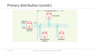
Primary distribution (contd.)
27-11-2019
6.
Prepared by: Mr.Amit Kr. Roy, Asst. Prof., EE Dept., JSSATEN 6
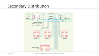
Secondary Distribution
• It is that part of AC distribution system which includes the range of voltages at which the ultimate consumer
utilizes the electrical energy.
• The secondary distribution employs 400/230 V, 3-phase, 4-wire system.
• The primary distribution circuit delivers power to various substations, called distribution substations.
• The substations are situated near the consumers’ localities and contain stepdown transformers.
• At each distribution substation, the voltage is stepped down to 400 V and power is delivered by 3-phase,4-
wire a.c. system.
• The voltage between any two phases is 400 V and between any phase and neutral is 230 V. The single phase
domestic loads are connected between any one phase and the neutral, whereas 3-phase 400 V motor loads are
connected across 3- phase lines directly.
27-11-2019
7.
Prepared by: Mr.Amit Kr. Roy, Asst. Prof., EE Dept., JSSATEN 7
Secondary Distribution
27-11-2019
8.
Prepared by: Mr.Amit Kr. Roy, Asst. Prof., EE Dept., JSSATEN 8
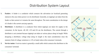
Distribution System Layout
1. Feeders: A feeder is a conductor which connects the sub-station (or localized generating
station) to the area where power is to be distributed. Generally, no tapping's are taken from the
feeder so that current in it remains the same throughout. The main consideration in the design
of a feeder is the current carrying capacity.
2. Distributor: A distributor is a conductor from which tapping's are taken for supply to the
consumers. In the layout, AB, BC, CD and DA are the distributors. The current through a
distributor is not constant because tapping's are taken at various places along its length. While
designing a distributor, voltage drop along its length is the main consideration since the
statutory limit of voltage variations is ± 6% of rated value at the consumers’ terminals.
3. Service mains: A service mains is generally a small cable which connects the distributor to the
consumers’ terminals
27-11-2019
9.
Prepared by: Mr.Amit Kr. Roy, Asst. Prof., EE Dept., JSSATEN 9
Classification of Distributed system
Radial System
Ring main system
Inter-connected system
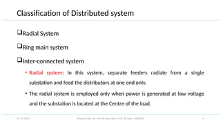
• Radial system: In this system, separate feeders radiate from a single
substation and feed the distributors at one end only.
• The radial system is employed only when power is generated at low voltage
and the substation is located at the Centre of the load.
27-11-2019
10.
Prepared by: Mr.Amit Kr. Roy, Asst. Prof., EE Dept., JSSATEN 10
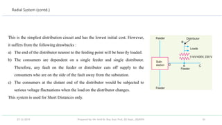
Radial System (contd.)
This is the simplest distribution circuit and has the lowest initial cost. However,
it suffers from the following drawbacks :
a) The end of the distributor nearest to the feeding point will be heavily loaded.
b) The consumers are dependent on a single feeder and single distributor.
Therefore, any fault on the feeder or distributor cuts off supply to the
consumers who are on the side of the fault away from the substation.
c) The consumers at the distant end of the distributor would be subjected to
serious voltage fluctuations when the load on the distributor changes.
This system is used for Short Distances only.
27-11-2019
11.
Prepared by: Mr.Amit Kr. Roy, Asst. Prof., EE Dept., JSSATEN 11
Ring Main System
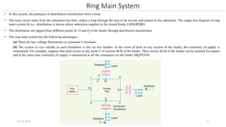
• In this system, the primaries of distribution transformers form a loop.
• The loop circuit starts from the substation bus-bars, makes a loop through the area to be served, and returns to the substation. The single line diagram of ring
main system for a.c. distribution is shown where substation supplies to the closed feeder LMNOPQRS.
• The distributors are tapped from different points M, O and Q of the feeder through distribution transformers.
• The ring main system has the following advantages :
(a) There are less voltage fluctuations at consumer’s terminals.
(b) The system is very reliable as each distributor is fed via two feeders. In the event of fault on any section of the feeder, the continuity of supply is
maintained. For example, suppose that fault occurs at any point F of section SLM of the feeder. Then section SLM of the feeder can be isolated for repairs
and at the same time continuity of supply is maintained to all the consumers via the feeder SRQPONM.
27-11-2019
12.
Prepared by: Mr.Amit Kr. Roy, Asst. Prof., EE Dept., JSSATEN 12
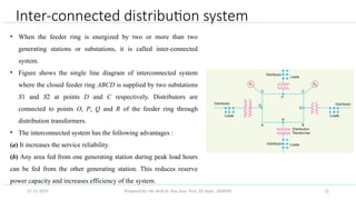
Inter-connected distribution system
• When the feeder ring is energized by two or more than two
generating stations or substations, it is called inter-connected
system.
• Figure shows the single line diagram of interconnected system
where the closed feeder ring ABCD is supplied by two substations
S1 and S2 at points D and C respectively. Distributors are
connected to points O, P, Q and R of the feeder ring through
distribution transformers.
• The interconnected system has the following advantages :
(a) It increases the service reliability.
(b) Any area fed from one generating station during peak load hours
can be fed from the other generating station. This reduces reserve
power capacity and increases efficiency of the system.
27-11-2019
13.
Prepared by: Mr.Amit Kr. Roy, Asst. Prof., EE Dept., JSSATEN 13
Design Considerations in Distribution System
• Good voltage regulation of a distribution network is probably the most important factor
responsible for delivering good service to the consumers. For this purpose, design of feeders and
distributors requires careful consideration.
(i) Feeders design consideration: A feeder is designed from the point of view of its current carrying
capacity while the voltage drop consideration is relatively unimportant. It is because voltage drop in a
feeder can be compensated by means of voltage regulating equipment at the substation.
(ii) Distributors design consideration: A distributor is designed from the point of view of the voltage drop
in it. It is because a distributor supplies power to the consumers and there is a statutory limit of voltage
variations at the consumer’s terminals (± 6% of rated value). The size and length of the distributor should
be such that voltage at the consumer’s terminals is within the permissible limits.
27-11-2019