
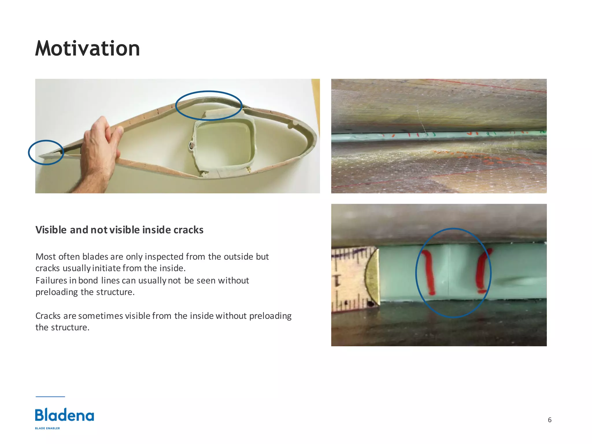
Download as PDF, PPTX
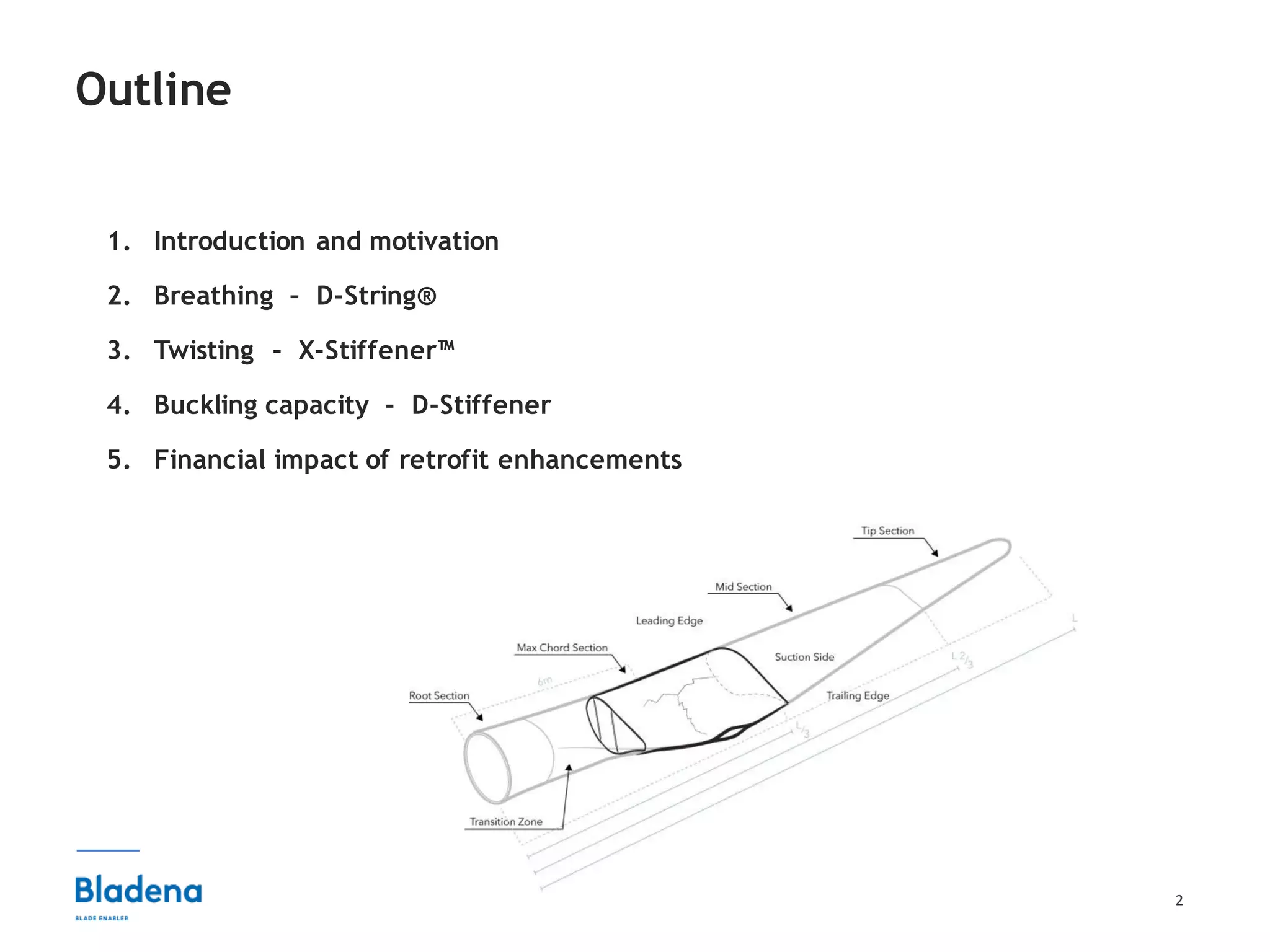

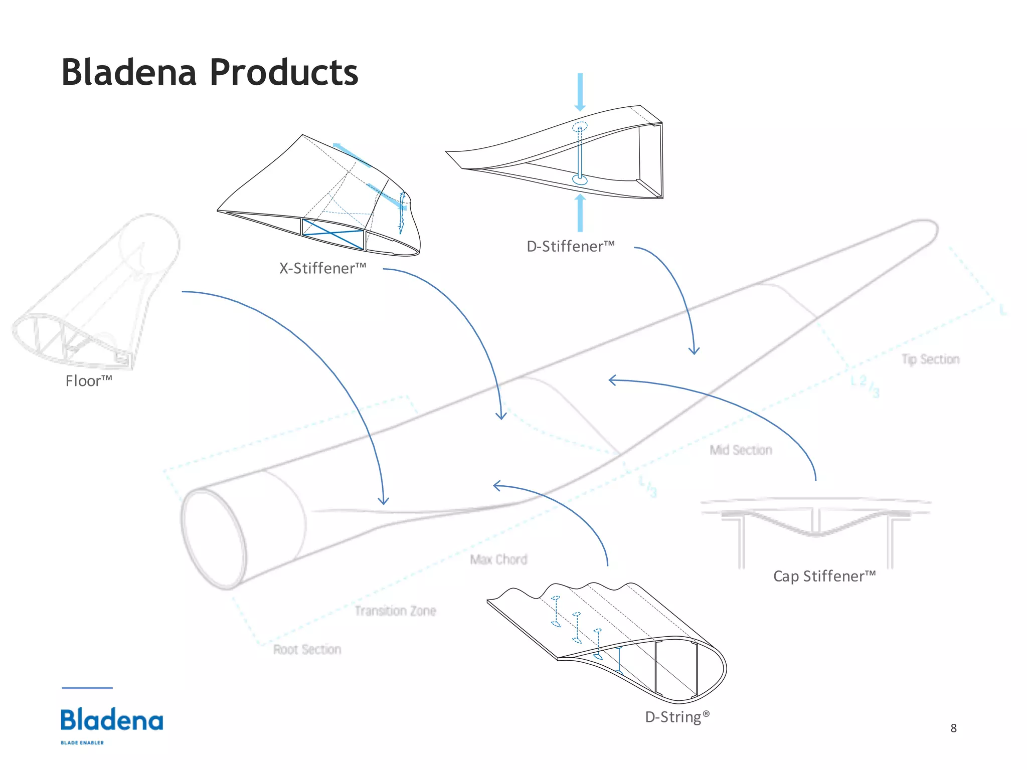
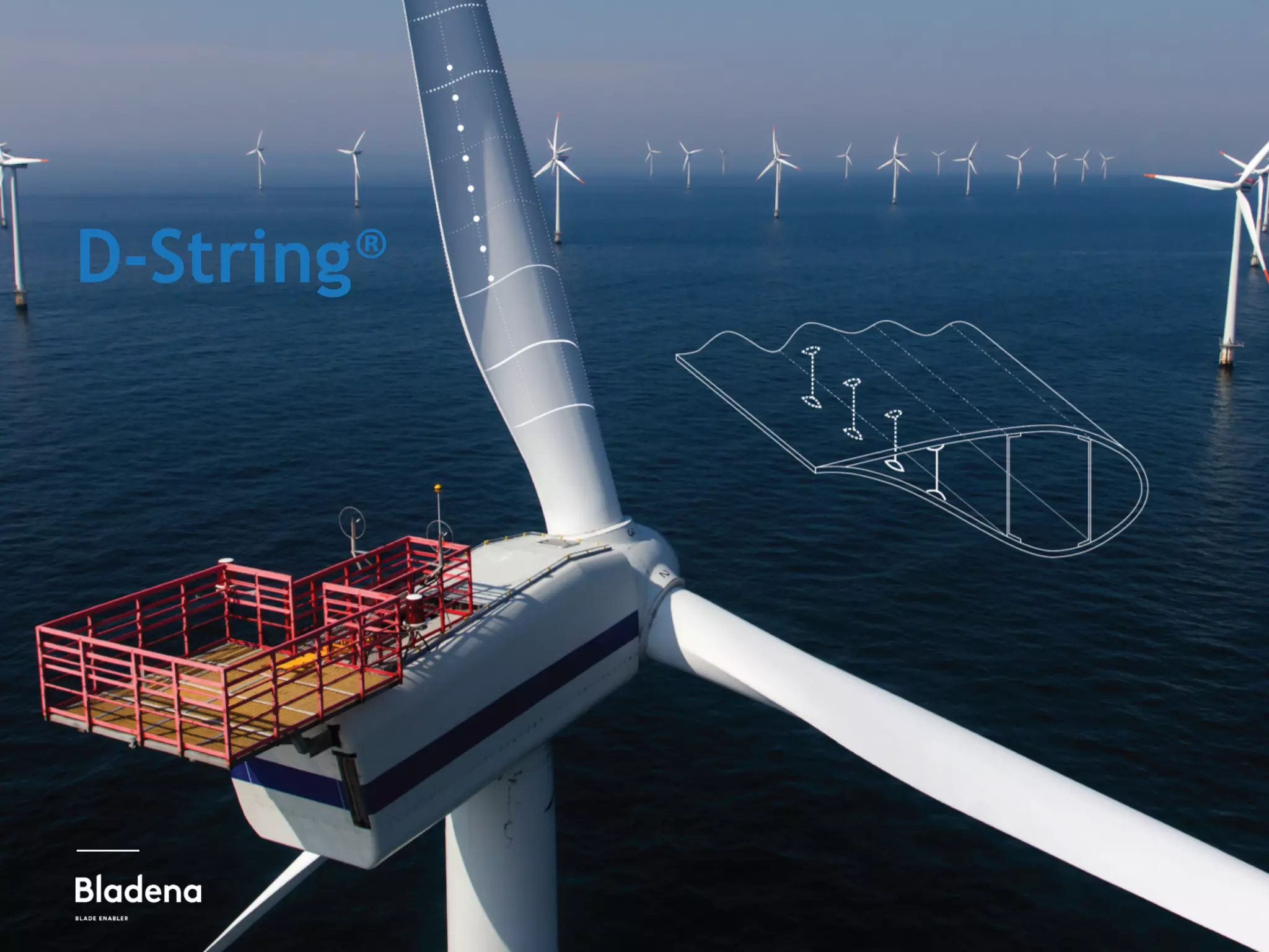
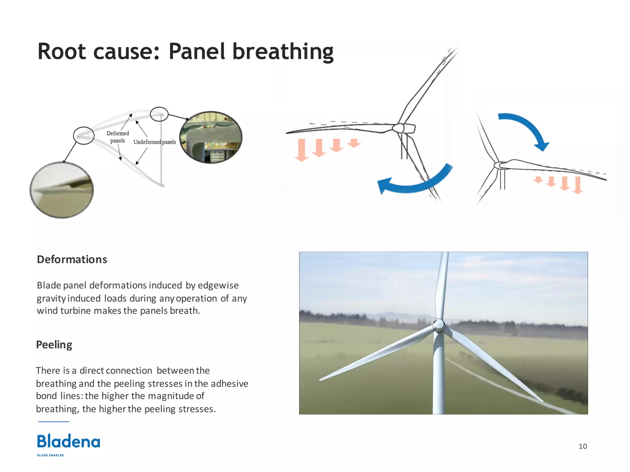


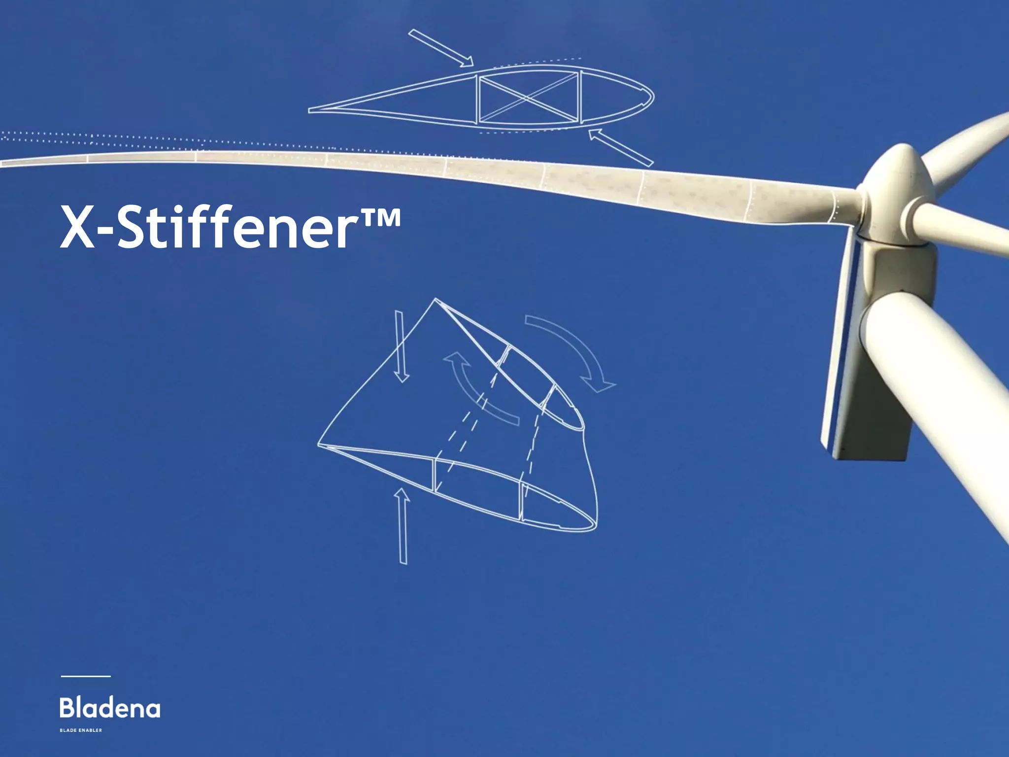


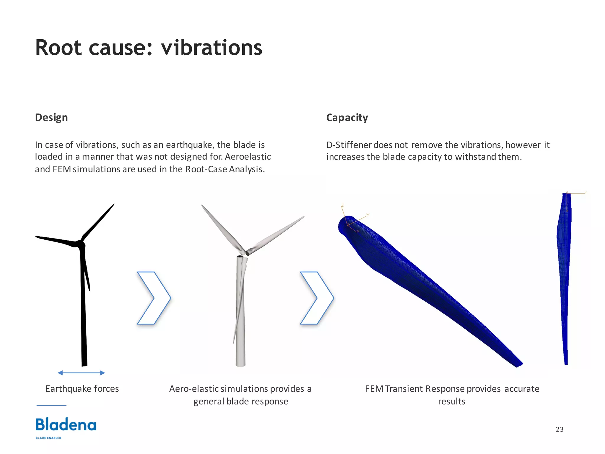


The document summarizes structural enhancements that can be made to wind turbine blades to improve their performance and reduce costs. It describes D-String, X-Stiffener, and D-Stiffener technologies developed by Bladena to address issues like blade panel breathing, twisting, and buckling. Testing and customer cases demonstrate how the retrofit technologies increase blade lifetime by reducing stresses and vibrations. The financial impact is a return on investment of less than two years through reduced maintenance costs and increased turbine uptime.


![Coded Agents – with UiPath SDK + LangGraph [Virtual Hands-on Workshop]](https://cdn.slidesharecdn.com/ss_thumbnails/codedagentsdeck-251215155422-5497c599-thumbnail.jpg?width=640&height=640&fit=bounds)


