Download to read offline
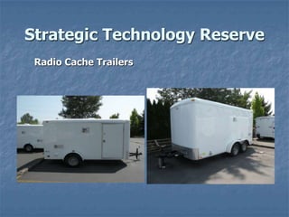


The document details the specifications and features of strategic technology reserve radio cache trailers, including trailer dimensions, electrical systems, securing equipment, and power systems. Each trailer contains mast systems for public safety and amateur radio, alongside solar power capabilities for operating radio equipment. Additionally, the document outlines instructions for using the solar panel and inverter systems, as well as safety measures regarding fuel usage.


