1. The document discusses various methods for processing metals including forming methods like forging, drawing, rolling, and extrusion as well as casting, powder processing, and welding.
2. It also covers thermal processing methods like annealing and how properties like hardness can be altered through quenching and controlled cooling after heating metals to certain temperatures.
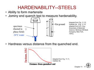
3. The effects of alloy content, quenching medium, and geometry on hardenability and resulting hardness are evaluated through tests like the Jominy end quench test.