This document provides a summary and overview of a Standards & Tolerances Guide published by the Queensland Building and Construction Commission (QBCC) in May 2014. It outlines that the tolerances and standards in the guide have been sourced from existing legislation, codes, and industry standards. The guide aims to provide a quick reference for building standards and tolerances in Queensland to reduce disputes. It acknowledges other references take precedence over the guide if any differences exist.


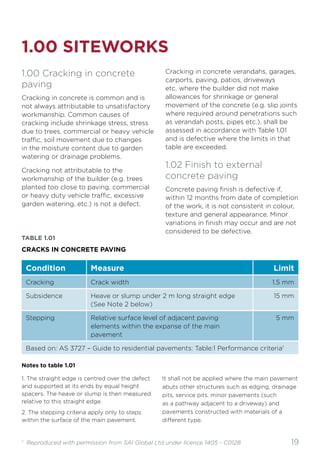
![12
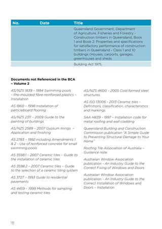
No. Date Title
AS 1273 1991 Unplasticized PVC (UPVC) downpipe and
fittings for rainwater
AS/NZS 1276 Acoustics—Rating of sound installation in
buildings and of building elements
Part 1 1999 Airborne sound insulation
[Note: Test reports based on AS 1276 — 1979
and issued prior to AS/NZS 1276.1 — 1999
being referenced in the BCA, remain valid. The
STC values in reports based on AS 1276 — 1979
shall be considered to be equivalent to Rw
values. Test reports prepared after the BCA
reference date for AS/NZS 1276.1 — 1999 must
be based on that version.]
AS 1288 2006 Glass in buildings—Selection and Installation
Amdt 1
Amdt 2
AS 1289 Methods of testing soils for engineering
purposes
Method 6.3.3 1997 Determination of the penetration resistance of
a soil — Perth sand penetrometer test
Amdt 1
AS 1397 2011 Continuous hot dip metallic coated sheet steel
and strip - coatings of zinc and zinc alloyed
with aluminium and magnesium
AS 1530 Methods for fire tests on building materials,
components and structures
Part 1 1994 Combustibility test for materials
Part 2 1993 Test for flammability of materials
Amdt 1
Part 4 2005 Fire-resistance test of elements of
construction
[Note: Subject to the note to AS 4072.1,
reports relating to tests carried out under
earlier editions of AS 1530 Parts 1 to 4 remain
valid. Reports relating to tests carried out after
the date of an amendment to a Standard must
relate to the amended Standard]](https://image.slidesharecdn.com/standardsandtolerancesguide0-230318122146-5bea327a/85/Standards_and_Tolerances_Guide_0-pdf-12-320.jpg)


![16
No. Date Title
AS 4055 2012 Wind loads for housing
AS 4072 Components for the protection of openings in
fire-resistant separating elements
Part 1 2005 Service penetrations and control joints
Amdt 1
[Note: Systems tested to AS 1530.4 prior to 1
January 1995 need not be retested to comply
with the provisions in AS 4072.1]
AS 4100 1998 Steel structures
Amdt 1
AS/NZS 4200 Pliable building membranes and underlays
Part 1 1994 Materials
Amdt 1
Part 2 1994 Installation requirements
AS 4254 Ductwork for air-handling systems in buildings
Part 1 2012 Flexible duct
Part 2 2012 Rigid duct
AS/NZS 4256 Plastic roof and wall cladding material
Part 1 1994 General requirements
Part 2 1994 Unplasticized polyvinyl chloride (UPVC)
building sheets
Part 3 1994 Glass fibre reinforced polyester (GRP)
Part 5 1996 Polycarbonate
AS/NZS 4505 2012 Garage doors and other large access doors
AS 4586 2013 Slip resistance classification of new pedestrian
surface materials
[Note: Test reports based on the 2004 edition
of AS/NZS 4586 and issued prior to the 2013
edition of AS 4586 being referenced in the
BCA remain valid. Test reports prepared after
the BCA reference date of the 2013 edition of
AS 4586 must be based on that version. For
the purposes of assessing compliance, the
slip-resistance classifications of V, W and X in
reports based on the 2004 edition of AS/NZS
4586 may be considered to be equivalent to
slip-resistance classifications of P5, P4 and P3
respectively in the 2013 edition of AS 4586.]](https://image.slidesharecdn.com/standardsandtolerancesguide0-230318122146-5bea327a/85/Standards_and_Tolerances_Guide_0-pdf-16-320.jpg)