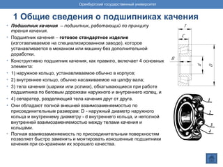
Ceramic bearings are typically constructed with a ferrous inner and outer ring or race with ceramic balls in the place of steel. Ceramic bearings offer many advantages over all steel bearings, such as higher speed and acceleration capability, increased stiffness, lower friction and more. Ceramic balls are also nonconductive. Ceramic bearings are available in all standard industry configurations such as, angular bearings, thrust bearing, pillow block bearing, needle bearings, and roller bearings.
This document discusses customizing the TYPO3 backend interface through various configuration options. It covers customizing the backend login screen, page tree, elements, content editing interface, modules, and more. Configuration is done primarily through Page TSconfig and user TSconfig files to modify existing backend behaviors and interfaces. The goal is to build a cozy and customized backend environment for editors.
efect of ductile to brittle transition temperturesanjay sahoo
This document summarizes a seminar on how the ductile to brittle transition temperature (DBTT) can affect ships. It discusses how the Titanic's steel structure failed due to brittle fracture from low temperatures. The DBTT is the temperature at which a material changes from ductile to brittle behavior. Several factors can influence a material's DBTT curve, including crystal structure, grain size, heat treatment, and composition. Modern steels have lower sulfur contents and smaller grains, leading to higher transition temperatures than the steel used for the Titanic. Understanding how materials behave at low temperatures helps make ships safer by considering fracture risks during design.
Cold isostatic pressing (CIP) is a technique where high pressure is applied uniformly to metal powder sealed in a flexible container. This compacts the powder to a density of 75-85% without die wall friction, resulting in a part with uniform density and no residual stresses. There are two methods - the wet bag process suited for batch production of complex parts, and the dry bag process using a fixed mold for mass production. CIP is used to make intricate or long shapes out of materials like titanium, tool steels, tungsten, and molybdenum powders.
Powder metallurgy is a process that involves producing metal powders and using them to make finished parts. It consists of three main stages: 1) physically powdering the primary material, 2) injecting the powder into a mold or passing it through a die to form a weakly cohesive pre-form, and 3) applying high pressure, temperature, and time to fully form the final part. The process allows for high production rates, low material waste, and flexibility in alloy choices. Parts are made through blending metal powders, compacting them into shapes using dies and presses, and sintering the compacts to strengthen the bonds between particles.
This document discusses various technological properties of materials:
Machinability is defined as how easily a material can be cut or shaped by tools. It depends on properties like hardness, grain size, lubricants used. White cast iron is not machinable while grey cast iron is easy to machine.
Weldability is how easily a material can be joined to itself or other materials through welding. It depends on properties like composition, strength at high temperatures, and thermal properties.
Workability/formability is how easily a material can be shaped while solid through processes like forging and extrusion without cracking. Cold workability refers to shaping cold materials while hot workability is shaping hot materials.
Castability is how easily
Advanced welding ,casting , forming processes PDF by badebhau4@gmail.comEr. Bade Bhausaheb
The document discusses advanced manufacturing processes including friction stir welding, advanced die casting, and tooling. It provides details on friction stir welding such as how it works as a solid-state welding process without reaching melting point. It also discusses advantages like producing high quality welds with fewer defects compared to traditional welding. The document then covers various types of tooling used for sheet metal pressing, molding, jigs/fixtures, and their applications in press working processes like blanking, piercing, bending, drawing, and others.
MAGNETIC FLUX CONTROL IN INDUCTION INSTALLATIONSFluxtrol Inc.
http://fluxtrol.com
It is well known that performance of some induction systems may be
significantly improved by application of magnetic flux controllers. They are used to
concentrate, shield and/or redistribute the magnetic field which generates power in the part. Theoretical and practical evidences are presented in the paper, which show that there is still significant potential for improvement in innovative and traditional induction technologies due to magnetic flux control. Utilizing magnetic flux controllers in heat treating processes results in excellent heat pattern control and improvement of parameters of inductors and entire power delivery systems. In melting systems, especially in the case of vacuum furnaces, cold crucible and other specialty furnaces, the magnetic control can provide energy savings, magnetic field shielding, shorter melting cycles and optimized field distribution for metallurgical processes. Comparison of different groups of materials for magnetic flux control (laminations, ferrites and Soft Magnetic Composites, aka Magnetodielectrics) is also presented in the paper. Several examples of magnetic flux control illustrate the presented material based on more than 20 years of R&D and practical experience of scientists and practitioners at Fluxtrol Inc.
Applications of Non Traditional Machining (NTM) in Pharmaceutical Industry AMan Ahmed
This document discusses applications of nanotechnology in the pharmaceutical industry. It covers using non-traditional machining (NTM) like wire EDM to recondition dies and fabricate carbon nanotubes and graphene. Carbon nanotubes produced by NTM could be used for drug delivery by selectively targeting organs with low toxicity. Graphene fabricated using ultrasonic machining and laser reduction shows potential for fighting antibiotic-resistant bacteria. The document also recommends reconditioning dies through inserts and developing new nano-materials to reduce costs.
Ango mould & plastic co., ltd. (company profile )Jenny Hu
Ango Mold is a professional plastic injection mould & molding manufacturer over 10 years. Precise mold, Medium and Large size mold, Double-injection mold, Blow mold, Insert mold, Stack mold, Multi-cavity mold and Die-casting mold are can be made in Ango Mold. We meet 98% of satisfy for the quality, and 97% of meeting lead time for all of our present customers. Looking forward to work with you.
The document provides an overview of additive manufacturing (AM), also known as 3D printing. It discusses the evolution of AM from its origins in the 1980s to recent developments. The key differences between AM and conventional CNC machining are described, including differences in the manufacturing process, materials used, precision, speed of production, and versatility. AM builds objects up in layers while CNC machining cuts material away. CNC machining generally allows for more durable, precise parts at larger scales and higher speeds of production than typical AM processes.
Centrifugal casting is a method that uses centrifugal force to distribute molten metal into rotating molds. There are three main types: true centrifugal casting produces hollow cylindrical parts like pipes by pouring metal into a horizontally or vertically rotating mold; semicentrifugal casting makes parts with rotational symmetry like wheels with spokes; and centrifuging forces molten metal from the center into stationary molds placed around the axis of rotation. Centrifugal casting results in dense, high quality castings with variations in properties depending on their distance from the center of rotation.
The document discusses microstructures in steels and other alloys. It includes images and descriptions of different microstructures like pearlite, martensite, bainite, and ferrite that form under various cooling conditions from austenite. It also discusses microstructures in cast irons like spheroidal graphite, flake graphite, and ledeburite. The final section discusses sealed quench furnaces and includes images of loads of components prepared for case hardening and quenching treatments.
These slides use concepts from my (Jeff Funk) course entitled analyzing hi-tech opportunities to show how the cost and performance of additive manufacturing/3D printing is experiencing rapid improvements and thus it is becoming economically feasible for many new applications. All 3D printers have benefited from improvement sin microprocessors and sensors, which have enabled better process control. One new and one existing technique and the impact of improvements in electronic components on the performance and cost of additive manufacturing are discussed. First, continuous liquid interface production is a new technique that utilizes a unique design of digital light processing, a deadzone, and an oxygen permeable window. Improvements in the resolution of DLP, a form of MEMS, are occurring as smaller feature sizes are achieved, in the same way that increases in the number of transistors are achieved as transistor gate lengths are reduced. Second, an existing approach, Selective laser sintering, experiences improvements as higher powered lasers emerge. This technique melts metal powder and wires with an Ytterbium fiber laser whose power capabilities continue to be improved. This technique has already enabled GE to reduce the number of parts for an engine nozzle from 18 to 1, the weight by 25%, and the costs by a similar amount. The number of applications for SLA is expected to grow as the technique is improved through the use of higher powered lasers.
Powder metallurgy (P/M) is used to produce parts when other metalworking processes cannot be used due to high melting points or difficulty in machining. P/M involves producing metal powders, blending them with other powders, compacting the blended powder into a "green" part, sintering the part to bond the powders together, and finishing the part. Near 70% of P/M production is for automotive applications due to its ability to produce parts with good dimensional accuracy and controllable porosity.
This document summarizes a presentation on ductile mode machining of glass. It begins with an outline of the presentation topics, which include an introduction to background and objectives, a literature review, concepts of ductile mode machining of glass including experimental setup and testing. Results are discussed relating flank wear and machining time to feed rate and surface roughness. Optimal cutting conditions for achieving ductile mode machining are a moderate feed rate and axial depth of cut of 0.4μm at 80 nm/rev feed rate. Below this critical feed rate, plowing occurs while above it causes brittle fracture. References cited relate feed rate to ductile-brittle transition and stress intensity factors.
The document provides information about a 6 high reversible cold rolling mill, including:
1. Schematic diagrams and descriptions of the mill components including work rolls, intermediate rolls, back up rolls, uncoilers, recoilers, and tension reels.
2. Specifications for the mill such as thickness reduction capabilities, width tolerances, tension limits, and roll dimensions and frequencies.
3. Descriptions of equipment used in the mill like the pay off reel, three roll feeder, entry and delivery tension reels, and the roll changing car.
4. Explanations of concepts like roll deflection, shape definition, and types of defects that can occur like rust, coolant patches
The document discusses powder metallurgy, including its production methods, materials, and applications. Powder metallurgy involves compressing metal powders into shapes and sintering them to bond the particles. Key steps are blending powders, pressing them into green compacts, and sintering to increase strength. Powder metallurgy allows mass producing net-shape parts and fabricating alloys otherwise difficult to make. Common materials are iron and steel alloys and applications include filters, bearings, and lamp filaments.
The lost wax casting process involves making a wax pattern, coating it with refractory material to create a mold, melting out the wax to leave a cavity, and pouring molten metal to create a casting. Key steps include making an initial wax pattern, coating it with layers of refractory clay to form a mold, baking the mold to harden it and melt the wax, and pouring molten metal into the resulting cavity. This ancient process allows for creating intricate casting designs.
The document outlines the methodology for conducting a failure analysis, including collecting background information on the failed component, examining the failure site, taking specimens for laboratory testing, analyzing test data, and preparing a report documenting the sequence of events leading to failure and providing recommendations. The process is multidisciplinary and aims to determine the root cause of failure through a systematic approach involving visual inspection, metallurgical examination, and mechanical testing of specimens from the failed component.
Дисковый поворотный затвор (двухэксцентриковый затвор) - элемент трубопроводной арматуры, используемый для перекрытия потока среды.
В настоящее время использование дисковых поворотных затворов с двойным эксцентриситетом оправданно в тех элементах технологической системы, где предъявляются определенные требования к строительной длине элемента.
В данной статье будут отражены наиболее важные характеристики таких затворов.
1. ФГБОУ ВПО «ОРЕНБУРГСКИЙ
ГОСУДАРСТВЕННЫЙ УНИВЕРСИТЕТ»
КАФЕДРА «МЕТРОЛОГИЯ,
СТАНДАРТИЗАЦИЯ И
СЕРТИФИКАЦИЯ»
Вольнов А.С.
ПОДШИПНИКИ КАЧЕНИЯ
Оренбург 2015
Оренбургский государственный университет
2. Оренбургский государственный университет
СОДЕРЖАНИЕ
1 Общие сведения о подшипниках качения
2 Нормативные документы
3 Классы точности подшипников качения
4 Условные обозначения подшипников качения
5 Расчет и выбор посадок подшипников качения
Подшипник качения (видео)
6 Классификация подшипников качения
Список использованных источников
3. 1 Общие сведения о подшипниках качения
• Подшипник качения – подшипник, работающий по принципу
трения качения.
• Подшипник качения − готовое стандартное изделие
(изготавливаемое на специализированном заводе), которое
устанавливается в механизм или машину без дополнительной
доработки.
• Конструктивно подшипник качения, как правило, включает 4 основных
элемента:
• 1) наружное кольцо, устанавливаемое обычно в корпусе;
• 2) внутреннее кольцо, обычно насаживаемое на цапфу вала;
• 3) тела качения (шарики или ролики), обкатывающиеся при работе
подшипника по беговым дорожкам наружного и внутреннего колец, и
• 4) сепаратор, разделяющий тела качения друг от друга.
• Они обладают полной внешней взаимозаменяемостью по
присоединительным размерам: D - наружный диаметр наружного
кольца и внутреннему диаметру - d внутреннего кольца, и неполной
внутренней взаимозаменяемостью между телами качения и
кольцами.
• Полная взаимозаменяемость по присоединительным поверхностям
позволяет быстро заменять и монтировать изношенные подшипники
качения при со-хранении их хорошего качества.
Оренбургский государственный университет
4. Достоинства и недостатки подшипников качения
Достоинства подшипников качения:
1. малые потери на трение (приведённый к цапфе
вала коэффициент трения подшипников качения
f = 1,5⋅10-3
…6⋅10-3
);
2. малые габариты в осевом направлении;
3. низкая стоимость при высокой степени
взаимозаменяемости;
4. малый пусковой момент сопротивления,
практически одинаковый с моментом, действующим
в процессе установившегося движения;
5. малый расход смазочных материалов и,
следовательно, малый объём работ по
обслуживанию;
6. пониженные требования к материалу и
качеству обработки цапф.
Недостатки подшипников качения:
1. высокая чувствительность к ударным и
вибрационным нагрузкам вследствие малых
площадей контакта между телами качения и
беговыми дорожками колец подшипника;
2. большие габариты в радиальном направлении;
3. малая надёжность в высокоскоростных приводах.
Оренбургский государственный университет
5. 2 Нормативные документы
• Термины и определения подшипников качения и их
элементов регламентирует ГОСТ 24955-81;
• Допуски и отклонения размеров, формы, точности
вращения и зазоров ненагруженных подшипников -
ГОСТ 25256-2013;
• Основные размеры подшипников устанавливает
ГОСТ 3478-2012;
• ГОСТ 520-2011 регламентирует методы контроля
точности отдельных колец и собранных подшипников, а
также показатели обязательного ресурса, технические
требования на материалы и термообработку,
шероховатость присоединительных поверхностей, тел
качения и дорожек качения.
Оренбургский государственный университет
6. 3 Классы точности подшипников качения3 Классы точности подшипников качения
• В зависимости от указанных показателей точности по ГОСТ 520-2011
установлены следующие классы точности, указанные в порядке повышения
их точности:
• 0, 6, 5, 4, 2, Т - для шариковых и роликовых радиальных и шариковых
радиально-упорных подшипников.
• 0, 6, 5, 4, 2 - для упорных, упорно-радиальных подшипников (без изменения
как в ГОСТ 520-2011).
• 0, 6Х, 6, 5, 4, 2 - для роликовых конических.
• Установлены дополнительные классы точности подшипников - 8 и 7 - ниже
класса точности 0 для применения по заказу потребителей в
неответственных узлах.
• В зависимости от наличия требований по уровню вибрации или уровня
других дополнительных требований установлены три категории
подшипников - А, В, С.
• При выборе следует ориентироваться на 0 класс точности для большинства
механизмов общего назначения.
• Более высокие классы точности применяют при больших частотах вращения
и в случаях, когда требуется высокая точность вращения вала (например,
для шпинделей шлифовальных и других прецизионных станков, для
авиационных двигателей, приборов).
Оренбургский государственный университет
7. 4 Условные обозначения подшипников качения
Оренбургский государственный университет
Стандартом установлены
классы точности 0, 6,5,4,2 (в
порядке повышения
точности), класс 0 не
маркируется
Класс точности Основное условное обозначение
Другие конструктивные
особенности
Серия по ширине
Характеризуют диаметр подшипника на вал
Обозначение 00 01 02 03 Частное от деления
диаметра посадки на 5
Диаметр
посадки, мм
10 12 15 17 15<d<495
Незначащие нули слева в основном условном
обозначении подшипника не указываются
Серия по наружному
диаметру
Конструктивные особенности
Характеризует тип подшипника
Обозна-
чение
Тип
0 Шариковый радиальный однорядный
1 Шариковый радиальный двухрядный
сферический
2 Роликовый радиальный однорядный с короткими
цилиндрическими роликами
3 Роликовый радиальный двурядный сферический
4 Роликовый радиальный с длинными
цилиндрическими роликами или иглами
5 Роликовый с витыми роликами
6 Шариковый радиально-упорный
7 Роликовый радиально-упорный
8 Шариковый упорный
9 Роликовый упорный
8. Серии подшипников каченияСерии подшипников качения
• Для каждого типа подшипника при одном и том же внутреннем диаметре
имеются различные серии, отличающиеся размерами колец и тел
качения.
В зависимости от размера наружного диаметра подшипники бывают:
• сверхлегкие;
• особо легкие (1);
• легкие (2);
• средние (3);
• тяжелые (4).
В зависимости от ширины
подшипника серии подразделяются на:
• особо узкие;
• узкие;
• нормальные;
• широкие;
• особо широкие.
Подшипники качения маркируют нанесением на торец колец ряда цифр
и букв, условно обозначающих внутренний диаметр, серию, тип,
конструктивные разновидности, класс точности и др.
Оренбургский государственный университет
9. Обозначение подшипников каченияОбозначение подшипников качения
Две первые цифры справа обозначают его внутренний диаметр d.
Для подшипников с d=20..495 мм размер внутреннего диаметра
определяется умножением указанных двух цифр на 5. Третья цифра справа
обозначает серию диаметров от особо легкой серии (1) до тяжелой (4).
Четвертая цифра справа обозначает тип подшипника:
Пятая или пятая и шеста цифры справа обозначают отклонение
конструкции подшипника от основного типа.
Седьмая цифра справа обозначает серию ширин. Цифры 2, 4, 5, 6,
стоящие через тире впереди цифр у основного обозначения подшипника,
указывают его класс точности. Нормальный класс точности обозначается
цифрой 0, которая не проставляется. Сверхвысоким классом точности
является 2, а затем в порядке понижения точности следует 4, 5, 6 и 0.
В условном обозначении подшипников могут быть дополнительные
знаки, характеризующие изменение металла деталей подшипника,
специальные технологические требования и т. д. В качестве примера
рассмотрим подшипник 7309. Он имеет диаметр d=45 мм, среднюю серию
диаметров. Приведенный в качестве примера подшипник является
роликовым коническим и имеет нормальный класс точности.
Оренбургский государственный университет
10. 5 Расчет и выбор посадок подшипников качения
• 5.1 Для данного в задании подшипника производят расшифровку его условного обозначения
и по ГОСТ 8338-75 определяют его номинальные размеры: внутренний диаметр внутреннего
кольца d, мм; наружный диаметр наружного кольца D, мм; ширину подшипника В, мм;
ширину фаски r, мм.
• 5.2 Производится анализ условий работы подшипникового узла (нагружения колец
подшипника, перегрузки подшипника) и определяется вид нагружения. Виды нагружения
также могут быть указаны в задании.
• 5.3 В случае циркуляционного нагружения кольца подшипника посадка выбирается по
интенсивности радиальной нагрузки на посадочной поверхности:
где FR – радиальная нагрузка на опору, кН;
b – рабочая ширина посадочной поверхности кольца подшипника за вычетом фасок
(b = B – 2r), м;
k1 – динамический коэффициент посадки. Зависит от характера нагрузки:
- k1=1 при перегрузке до 150 %, умеренных толчках и вибрации;
- k1=1,8 при перегрузке до 300 %, сильных толчках и вибрации;
k2 - коэффициент, учитывающий степень ослабления посадочного натяга при полом вале
или тонкостенном корпусе (если вал сплошной, то k2 = 1).
k3 - коэффициент неравномерности распределения радиальной нагрузки FR между рядами
роликов в двухрядных конических роликоподшипниках или между сдвоенными
шарикоподшипниками при наличии осевой нагрузки Fa на опору.
Оренбургский государственный университет
,kkk
b
F
P 321
R
R ⋅⋅⋅=
11. Расчет и выбор посадок подшипников качения
Таблица - Значение коэффициентов k2, k3
βFa
/Fr
ctgdв
/d или
D/Dk
Коэффициент k2
k3
Для вала Для корпуса
свыше до D/d<1,5 D/d=1,5÷2,0 D/d>2÷3
Для всех
подшипников
свыше до
-
0,4
0,7
0,8
0,4
0,7
0,8
-
1,0
1,2
1,5
2,0
1,0
1,4
1,7
2,3
1,0
1,6
2,0
3,0
1,0
1,1
1,4
1,8
-
0,2
0,4
0,6
1,0
0,2
0,4
0,6
1
1,0
1,2
1,4
1,6
2,0
Примечание: d и D- соответственно диаметры отверстия и наружной поверхности
подшипника; dв
- диаметр отверстия полового вала; Dk
- диаметр наружной поверхности
тонкостенного корпуса.
12. Расчет и выбор посадок подшипников
качения
Оренбургский государственный университет
Таблица - Посадки подшипников качения (соединение: корпус - наружное
кольцо)
Вид нагружения наружного
кольца
Режим работы подшипника Поле допуска отверстия
Местное Нормальный или лёгкий
Нормальный или тяжёлый
Наружное кольцо может
перемещаться в осевом
направлении
Н7
Н8
Js6
Js7
Циркуляционное Нормальный или тяжёлый М7
N7
Колебательное Нормальный или тяжёлый
Нормальное кольцо не
перемещается в осевом
направлении
Наружное кольцо легко
перемещается в осевом
направлении
К7
13. Расчет и выбор посадок подшипников
качения
Оренбургский государственный университет
Схема распределения
нагрузки
между телами
качения в подшипнике
Примечание: В процессе работы тела качения катятся по дорожкам
качения колец, одно из которых в большинстве случаев неподвижно.
Распределение нагрузки между несущими телами качения
неравномерно и зависит от величины радиального зазора в
подшипнике и от точности геометрической формы его деталей.
5.4 После определения интенсивности
нагрузки РR кольца, испытывающего
циркуляционное нагружение определяется поле
допуска сопрягаемой с данным кольцом детали
(вала или отверстия корпуса).
Для данного поля допуска по ГОСТ 25347-82
определяются предельные отклонения (либо es и
ei или ES и EI) размеров посадочных поверхностей
вала и отверстия (корпуса).
Отклонения диаметров d или D внутреннего
или наружного кольца подшипника принимаются в
соответствии с ГОСТ 520-2011.
14. Расчет и выбор посадок подшипников качения
Таблица - Допускаемые интенсивности нагрузок на посадочных поверхностях
валов и корпусов
Диаметр d
отверстия внутреннего
кольца подшипника, мм
Допускаемые значения PR
, кН/м
Поле допуска для вала
js6
, js5 k6, k5 m6, m5 n6, n5
Св. 18 до 80
» 80 » 180
» 180 » 360
»360 » 630
До 300
» 600
» 700
» 900
300-1400
600-2000
700-3000
900-3500
1400-1600
2000-2500
3000-3500
3500-5400
1600-3000
2500-4000
3500-6000
5400-8000
Диаметр D наружного
кольца, мм
Поле допуска для корпуса
K7, K6 M7, M6 N7, N6 P7
Св. 50 до 180
» 180 » 360
» 360 » 630
» 630 »1600
До 800
» 1000
» 1200
» 1600
800-1000
1000-1500
1200-2000
1600-2500
1000-1300
1500-2000
2000-2600
2500-3500
1300-2500
2000-3300
2600-4000
3500-5500
Примечание - Допускаемые значения PR
рассчитаны по средним значениям посадочных натягов.
Далее рассчитываются значения наибольшего натяга и наибольшего зазора,
строится схема полей допусков.
15. Расчет и выбор посадок подшипников качения
Нагружение
Посадочные
диаметры, мм
Посадка
Тип
подшипникана вал
в корпус стальной или
чугунный
неразъемный разъемный
Спокойное или с
умеренными
толчками и
вибрацией;
перегрузка до 150 %
До 80 h5, h6, g5 H6, H7
H6, H7, H8*
Все, кроме
штампованных
игольчатых
Св. 80 до 260 g6,f6*, js
6
G6, G7
Св. 260 до 500
500 » 1600
f6, js
6
F7, F8
С ударами и
вибрацией;
перегрузка до 300 %
До 80
h5, h6
Js
6, Js
7
Js
6, Js
7
Все, кроме
штампованных
игольчатых и
роликовых конических
двухрядных
Св. 80 до 260
H6, H7Св. 260 » 500
» 500 » 1600
g5, g6
* Применять при частоте вращения подшипника не более 0,6nпр
(nпр
- предельно допускаемая частота вращения).
Таблица - Рекомендуемые посадки для колец при местном нагружении
5.5 В случае местного нагружения подшипникового кольца рекомендуемые
поля допусков вала и отверстия корпуса под внутренние и наружные кольца
подшипников приведены в таблице. По данной таблице определяется поле
допуска сопрягаемой с данным кольцом детали (вала или отверстия корпуса).
16. Расчет и выбор посадок подшипников качения
5.6 В случае колебательного нагружения подшипникового кольца
рекомендуемые поля допусков вала и отверстия корпуса под внутренние и
наружные кольца подшипников приведены в таблице. По данной таблице
определяется поле допуска сопрягаемой с данным кольцом детали (вала или
отверстия корпуса).
Шариковые и роликовые радиальные подшипники
Вид нагружения
кольца
Поле допуска Посадка
вала отверстия на валу в отверстии
Колебательное js
4; js
5; js
6 JS
4; JS
5; JS
7
L2/js
4; L4/js
5; L5/js
5;
L6/js
6; L0/js
6
JS
4/I2; JS
5/I4; JS
5/I5;
JS
7/I6; JS
7/I0
Примечания - 1. При частотах вращения, превышающих предельные, для местнонагруженных колец подшипника
следует использовать в посадках поля допусков с основными отклонениями jS
и JS
. 2. Допускается применение в
посадках при необходимости полей допусков ограниченного применения j5; j6; J6; j7.
Таблица - Рекомендуемые поля допусков и посадки шариковых и роликовых
радиальных, радиально- упорных и упорных подшипников для колебательного
нагружения колец по ГОСТ 3325-85
17. По форме тел качения подшипники
качения классифицируют на:
Оренбургский государственный университет
Шариковые предпочтительно применять при высоких скоростях и малых
нагрузках
18. Тела качения подшипников
Оренбургский государственный университет
Шарик
Ролик
цилиндрический
короткий
Ролик
цилиндрический
длинный
Игла
Ролик витой Ролик
конический
Ролик
бочкообразный
симметричный
Ролик
сфероконический
19. Разновидности роликовых подшипников качения
Оренбургский государственный университет
- Роликоподшипники применяют при средних и малых скоростях и
повышенных нагрузках;
- Подшипники с витыми роликами применяют при динамических
нагрузках;
- Подшипники с бочкообразными и сфероконическими роликами
применяют в условиях несоосности внутреннего и наружного колец.
20. Классификация подшипников качения
• По количеству рядов тел качения –
однорядные, двух-, трёх- и более рядные;
• По направлению воспринимаемой нагрузки
– радиальные (нагрузка,
перпендикулярная оси вращения),
радиально-упорные (радиальная и осевая
нагрузки, причём радиальная нагрузка
больше осевой), упорно-радиальные
(радиальная и осевая нагрузки, но
радиальная нагрузка меньше осевой),
упорные (только под осевую нагрузку),
комбинированные (радиальная и осевая
нагрузки воспринимаются разными телами
качения);
• По самоустанавливаемости –
несамоустанавливающиеся и
самоустанавливающиеся;
Роликовый
радиальный
сферический
подшипник
Роликовый
радиальный
подшипник с
короткими
цилиндрическими
роликами
Роликовый
конический
подшипник
(радиально-упорный
роликоподшипник)
Оренбургский государственный университет
22. Схемы установки радиально-упорных подшипников
Регулировка подшипников
осуществляется
подбором металлических
прокладок между
крышкой подшипника и стаканом
Регулировка подшипников
осуществляется перемещением
внутреннего кольца одного из
подшипников посредством гайки
Оренбургский государственный университет
Перед монтажом подшипникового узла подшипник промывают в горячем минеральном масле или
бензине. Посадочные поверхности вала и корпуса чисто протирают и слегка смазывают. Для
облегчения посадки подшипника на вал с натягом подшипник предварительно нагревают до 80…
90°С в горячем минеральном масле. Сила напрессовки прикладывают к тому кольцу, которое
монтируется с натягом. Передача монтажных сил через тела качения недопустима. Во избежание
появления вмятин на дорожках качения при демонтаже подшипник захватывают за внутреннее
кольцо при удалении с вала и за наружное при удалении из корпуса.
23. Крепление наружных колец подшипников
качения в корпусе
Оренбургский государственный университет
Заплечниками
Торцевой
крышкой
Крышкой и
заплечником
Стаканом и
крышкой
Упорным бортом
подшипника
Врезной
крышкой
Пружинным
кольцом
Гайкой и
заплечником
24. ПОВРЕЖДЕНИЯ ПОДШИПНИКОВ
При разрушении подшипника бывает сложно точно определить причину.
Наиболее распространёнными причинами разрушения подшипников
являются: Износ; Уменьшение или истирание слоя смазки; Слишком высокая
температура окружающей среды; Перегрузка двигателя; Коррозия;
Неправильный монтаж; Повреждение при транспортировке; Вибрации
5
5
5
10
20
55
Повреждения при транспортировке
Некорректная установка
Загрязнение рабочей жидкости
Неправильный выбор подшипника когда
известна рабочая нагрузка и рабочая зона
Загрязнения твёрдыми включениями
Повряждения, связанные со смазкой
(недостаточная, неподходящая или старая
консистентная смазка)
Оренбургский государственный университет
26. Список использованных источников
1 ГОСТ 24955-81 Подшипники качения. Термины и
определения
2 ГОСТ 25256-2013 Подшипники качения. Допуски.
Термины и определения
3 ГОСТ 3478-2012 Подшипники качения.
Присоединительные размеры
4 ГОСТ 520-2011 Подшипники качения. Общие
технические условия
Оренбургский государственный университет