Downloaded 304 times


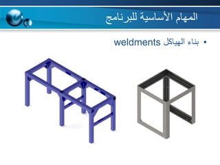

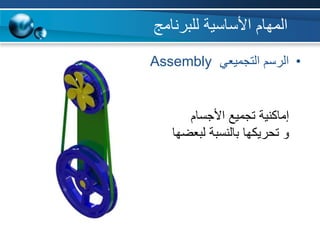


البرنامج هو برنامج سوليدووركس لتصميم الأبعاد ثلاثي الميكانيكي، وقد تم تطويره بواسطة شركة داسو سيستمس ويتضمن مجموعة من المهام الأساسية والمتقدمة في التصميم الهندسي مثل إنشاء الأجسام، تشكيل السطوح، وتصميم القوالب. يتم استخدامه على نطاق واسع من قبل المهندسين والمصممين في جميع أنحاء العالم، ويعتمد في بعض الجامعات الألمانية كبرنامج رئيسي للطلبة. تشمل المهام المتقدمة أيضًا المحاكاة والتصنيع وحساب تكلفة التصميم، مما يجعله برنامجًا متكاملاً في مجالات الهندسة والتصميم.


