Download to read offline
![International Research Journal of Engineering and Technology (IRJET) e-ISSN: 2395-0056
Volume: 09 Issue: 03 | Mar 2022 www.irjet.net p-ISSN: 2395-0072
© 2022, IRJET | Impact Factor value: 7.529 | ISO 9001:2008 Certified Journal | Page 1738
Smart Terrain Adaptive Robotic Suspension System (S.T.A.R.S.S)
KushalModi1, Neel Pednekar2, Danish Natraj3, Vikas Pathak4, Krishna Gaikwad5
1,2,3,4Undergraduate Student, Dept. of Mechanical Engineering, Thakur College of Engineering and Technology,
Mumbai, Maharashtra, India
5Assistant Professor, Dept. of Mechanical Engineering, Thakur College of Engineering and Technology,
Mumbai, Maharashtra, India
---------------------------------------------------------------------***----------------------------------------------------------------------
Abstract - The present study is a proposition of a novel
suspension system that is intended to be of great use in the
field of autonomous or manned exploration primarily on
extra-terrestrial planets. This new approach to suspension
systems is fully electronic and uses negative feedback to
stabilize the chassis. This research article attempts to let the
reader go through the design process for thewholesuspension
system, including link design, dimensioning, electronic
component selection, and finally, the embedded C code to
attain the desired result. The reasons for choosing these
parameters are well addressed in the work. Multiple tests
were performed on a prototype that was built during this
project on a track that simulated undulating surfaces for the
robot to move on. Kinematic and structural analyses were
carried out to ensure the prototype could perform as desired.
These tests were constantly monitored using the open-source
software, Processing, which gave real-time readings for the
attitude of the chassis. The chassis model was drawn on
OpenGL for easy visualization of the rolling, pitching, and
yawing of the chassis. Multiple tests resulting in lots of code
tweaks have ultimately resulted in the fulfillment of the
objective.
Key Words: Active suspension, horizontal chassis, links,
electronics, cost-effective, etc.
1. INTRODUCTION
With planetary exploration becoming a major aim of all the
Superpowers in the world, newer innovative and effective
designs are wanted to travel on unknown terrains with
safety assured. Unseen and unexplored terrains posea great
threat to vehicles movement and its components. Many
designs are currently being researched upon and many
simple yet very effective solutions like the "Rocker-Bogie
Mechanism"[10][12] havesurpassedall complicationsandhave
become the almost ideal solution for planetary exploration.
Despite such mechanisms, there still exists the dream of
fluid-like movement on rough terrains at a comparatively
lower expense. We have decided to go with an independent,
centrally controlled suspension system that relies on
individual movements of the wheels to avoid roll instability.
A centrally controlled suspension means that the "brain",
that is, the microcontroller installed, controls the
movements of the wheels depending upon the input
parameters. We plan to introduce a simple yet cutting-edge
robotic suspension system that can be made by modifying a
4 bar link mechanism to maintain a nearlyhorizontal chassis
over considerable forms of undulating terrains. The
suspension movement is controlled by an IMU (Inertial
Measurement Unit) which relays attitude information tothe
microcontroller which processes this data and relays
instructions to the system of servo motors, which helps in
controlling and moving the link mechanism to attain a
perfectly horizontal chassis. In addition to extraterrestrial
expeditions, there has been a surge in military, energy
production projects whichdemanda suspensionsystemthat
is not sophisticated but at the same time, effective. With the
help of electronics and simple mechanics, smarter, lighter,
effective, and economical solutions for a larger spectrum of
systems can be achieved.
1.1 Background
A suspension system is a link between the wheels and the
body of a vehicle. It may comprise shock absorbers, springs,
and linkages, all arranged in diverse ways depending on the
purpose they are being utilized for. Over the past decades,
numerous and distinctive changes have been made and
advanced technologies keep coming through. Most of the
suspension systems succeed and fulfill the objective they
have been proposed for but there aren't as many
mechanisms that guarantee an unwavering chassis. With
modern developments in warfare, space explorations, and
automobiles, such a mechanism is much needed. After much
research and analysis, wehavecomeforth witha systemthat
applies the fundamentals of mechatronics to remotely
control a vehicle's suspension. Unlike the current market
leaders such as the MR fluid[1], pneumatics, and hydraulic-
based systems, this one would function with the use of
microcontrollers, gyroscopes, and accelerometers. It would
sense data from its surroundings and then with the help of a
series of programs, reciprocate and allow the body to be
stable. Such a system, when implemented on a larger scale
could prove to be very pragmatic.
1.2 Problem Statement
An ideal suspension system would be the one that is the
most efficient and relatively cheaper. When working on a
project, the first thing to keep in mind is the cost which is to
be kept minimal without hampering its effectiveness.](https://image.slidesharecdn.com/irjet-v9i3320-220920094802-63ace12c/85/Smart-Terrain-Adaptive-Robotic-Suspension-System-S-T-A-R-S-S-1-320.jpg)
![International Research Journal of Engineering and Technology (IRJET) e-ISSN: 2395-0056
Volume: 09 Issue: 03 | Mar 2022 www.irjet.net p-ISSN: 2395-0072
© 2022, IRJET | Impact Factor value: 7.529 | ISO 9001:2008 Certified Journal | Page 1738
Smart Terrain Adaptive Robotic Suspension System (S.T.A.R.S.S)
KushalModi1, Neel Pednekar2, Danish Natraj3, Vikas Pathak4, Krishna Gaikwad5
1,2,3,4Undergraduate Student, Dept. of Mechanical Engineering, Thakur College of Engineering and Technology,
Mumbai, Maharashtra, India
5Assistant Professor, Dept. of Mechanical Engineering, Thakur College of Engineering and Technology,
Mumbai, Maharashtra, India
---------------------------------------------------------------------***----------------------------------------------------------------------
Abstract - The present study is a proposition of a novel
suspension system that is intended to be of great use in the
field of autonomous or manned exploration primarily on
extra-terrestrial planets. This new approach to suspension
systems is fully electronic and uses negative feedback to
stabilize the chassis. This research article attempts to let the
reader go through the design process for thewholesuspension
system, including link design, dimensioning, electronic
component selection, and finally, the embedded C code to
attain the desired result. The reasons for choosing these
parameters are well addressed in the work. Multiple tests
were performed on a prototype that was built during this
project on a track that simulated undulating surfaces for the
robot to move on. Kinematic and structural analyses were
carried out to ensure the prototype could perform as desired.
These tests were constantly monitored using the open-source
software, Processing, which gave real-time readings for the
attitude of the chassis. The chassis model was drawn on
OpenGL for easy visualization of the rolling, pitching, and
yawing of the chassis. Multiple tests resulting in lots of code
tweaks have ultimately resulted in the fulfillment of the
objective.
Key Words: Active suspension, horizontal chassis, links,
electronics, cost-effective, etc.
1. INTRODUCTION
With planetary exploration becoming a major aim of all the
Superpowers in the world, newer innovative and effective
designs are wanted to travel on unknown terrains with
safety assured. Unseen and unexplored terrains posea great
threat to vehicles movement and its components. Many
designs are currently being researched upon and many
simple yet very effective solutions like the "Rocker-Bogie
Mechanism"[10][12] havesurpassedall complicationsandhave
become the almost ideal solution for planetary exploration.
Despite such mechanisms, there still exists the dream of
fluid-like movement on rough terrains at a comparatively
lower expense. We have decided to go with an independent,
centrally controlled suspension system that relies on
individual movements of the wheels to avoid roll instability.
A centrally controlled suspension means that the "brain",
that is, the microcontroller installed, controls the
movements of the wheels depending upon the input
parameters. We plan to introduce a simple yet cutting-edge
robotic suspension system that can be made by modifying a
4 bar link mechanism to maintain a nearlyhorizontal chassis
over considerable forms of undulating terrains. The
suspension movement is controlled by an IMU (Inertial
Measurement Unit) which relays attitude information tothe
microcontroller which processes this data and relays
instructions to the system of servo motors, which helps in
controlling and moving the link mechanism to attain a
perfectly horizontal chassis. In addition to extraterrestrial
expeditions, there has been a surge in military, energy
production projects whichdemanda suspensionsystemthat
is not sophisticated but at the same time, effective. With the
help of electronics and simple mechanics, smarter, lighter,
effective, and economical solutions for a larger spectrum of
systems can be achieved.
1.1 Background
A suspension system is a link between the wheels and the
body of a vehicle. It may comprise shock absorbers, springs,
and linkages, all arranged in diverse ways depending on the
purpose they are being utilized for. Over the past decades,
numerous and distinctive changes have been made and
advanced technologies keep coming through. Most of the
suspension systems succeed and fulfill the objective they
have been proposed for but there aren't as many
mechanisms that guarantee an unwavering chassis. With
modern developments in warfare, space explorations, and
automobiles, such a mechanism is much needed. After much
research and analysis, wehavecomeforth witha systemthat
applies the fundamentals of mechatronics to remotely
control a vehicle's suspension. Unlike the current market
leaders such as the MR fluid[1], pneumatics, and hydraulic-
based systems, this one would function with the use of
microcontrollers, gyroscopes, and accelerometers. It would
sense data from its surroundings and then with the help of a
series of programs, reciprocate and allow the body to be
stable. Such a system, when implemented on a larger scale
could prove to be very pragmatic.
1.2 Problem Statement
An ideal suspension system would be the one that is the
most efficient and relatively cheaper. When working on a
project, the first thing to keep in mind is the cost which is to
be kept minimal without hampering its effectiveness.](https://image.slidesharecdn.com/irjet-v9i3320-220920094802-63ace12c/75/Smart-Terrain-Adaptive-Robotic-Suspension-System-S-T-A-R-S-S-1-2048.jpg)
![International Research Journal of Engineering and Technology (IRJET) e-ISSN: 2395-0056
Volume: 09 Issue: 03 | Mar 2022 www.irjet.net p-ISSN: 2395-0072
© 2022, IRJET | Impact Factor value: 7.529 | ISO 9001:2008 Certified Journal | Page 1739
To cope up we've come up with the mechanism that we aim
to achieve would be feasible to build at a reasonableexpense
and produce more effective results.
1.3 Objectives
1. Stabilizes the chassis to make it almost horizontal,
with a very small degree of error.
2. Enhance efficiency.
3. The robot must be able to go over both smooth
undulating surfaces and sharp obstacles.
4. Cut down the maintenance-related.
5. For more load transfer & response.
1.4 Scope of project
The new suspension system can be a real breakthroughin
the field of robotic suspension systems. It would be a
modification and an improvement on previously existing
suspension systems and hence be more effective. The
suspension will help improve mobility on difficult terrains
for military and space explorationactivities.Thissuspension
system can be implemented on various kinds of wheeled
bots like the ones which have robotic arms or other
modifications and can result in an even more versatile robot
vehicle. Considering our project's deliverables, it can be an
upgrade as compared to previous systems. The use of
mechanical links as well as an automated system is
something that has not been explored to the utmost and it
could lead to further developments in the proposed field.
The coding of the program and obtaining the best materials
to maximize the potential of this study is a hurdle but it can
be overcome with apropos research and discussions.
2. LITERATURE REVIEW
An innovation in any field requires a properstudyofexisting
technologies which is why a major portion of the time ofthis
project was dedicated totheliteraturesurvey.Thishelped us
in understanding various current technologies, their
precision, advantages, and disadvantages. The following
table is a list of relevant published, patented, and
unpublished research around the world.
Sr
No.
Title Relevance
1. Yuxin Zhanga, Xinjie
Zhanga, Min Zhana,
Konghui Guoa, Fuquan
Zhaoc, Zongwei Liu-
Study on a novel
hydraulic pumping
regenerative
suspension for
vehicles
Hydraulic actuators werechosento
absorb shock. But ruled out due to
its cost
2. BMW- Dynamic Drive Employs the use of sensors to
detect the movement of wheels and
creates counter forces. Ruled out
because of cost.
3. Karl Iagnemma, Adam
Rzepniewski and
Steven Dubowsky -
Control of Robotic
Vehicles with Actively
Articulated
Suspensions in Rough
Terrain
A new mechanism to overcome roll
stability has made us think about a
simple approach.
4. Kazuo Tani, Osamu
Matsumoto, Shuuji
Kajita, Nobumasa
Shirai-Wheeled Robots
to Overcome Ground
Unevenness in
Construction Areas
A multi-functioning bot with 3
different mechanisms has made us
think over a mechanism that can
perform multiple tasks including
climbing stairs
5. Adibi Asl, H., Rideout,G-
Using lead vehicle
response to generate
preview functions for
active suspension of
convoy vehicles
A similar approach to PanshuoLiet
al [6]. Except a whole convoy was
mathematically modeled and
deflections in tire of one were
reading for the other. Can be
implementedwhenweuseCOBOTS
or swarms.
6. Panshuo Li, James Lam ,
Kie
Chung Cheung- Multi-
objective control for
active vehicle
suspension with
wheelbase preview [3]
Front-wheel movementswereused
as inputs to stabilize. This gives us
the ability to add pseudo wheels
whose movements we can track
Table -1: Tabulated findings from relevant research
around the world
Conclusions from Literature Survey
•There are 2 kinds of suspension systems - active and
passive. While passive suspension systems are purely
mechanical, active suspension systems are interfaced with
plenty of sensors and electronics for higher precision. Since
our suspension system has a lot of electronics involved (for
higher accuracy), it falls under active suspension systems.](https://image.slidesharecdn.com/irjet-v9i3320-220920094802-63ace12c/85/Smart-Terrain-Adaptive-Robotic-Suspension-System-S-T-A-R-S-S-2-320.jpg)
![International Research Journal of Engineering and Technology (IRJET) e-ISSN: 2395-0056
Volume: 09 Issue: 03 | Mar 2022 www.irjet.net p-ISSN: 2395-0072
© 2022, IRJET | Impact Factor value: 7.529 | ISO 9001:2008 Certified Journal | Page 1740
•Mostoftheactivesuspensionsystemsareveryexpensive
and require a lot of processing power. The suspension
systems involving hydraulics, pneumatics, and linear
actuators are very expensive as the components are very
costly.
•Purely kinematic-based suspension systems are not
precise enough, therefore a controlled kinematic suspension
system would be perfect.
•The current near-perfect solutions like the BMW's
dynamic drive[2] work well for really small vibrations and
bumps. The suspension systems which can overcome large
bumps are not precise enough which gives us our problem
statement. We need to comeup with a high-precisionsystem
that can overcome large bumps.
•The suspension system must have "auto-stabilization"[3]
which means it must be able to recover from all sorts of
unprecedented actuations due to rough terrain.
3. METHODOLOGY
We began by choosing an appropriate design for the link
mechanism[4]. Some of the mechanismsthatwereprominent
after discussions were –
o A laid-back bent link 1 degree of freedom
arm [Fig. 1(a)]
o Three tire chain supported wheel [Fig.
1(b)]
o Modified parallel four-bar linkage [Fig.
1(c)]
Fig -1: Types of Links
We started by analyzing various suspension systems thatare
currently used following which a detailed study of the
evolution of suspension mechanisms was done to know how
each of them worked.
The basic working principle of each system was studied
individually followed by the analysis of the flaws in each of
them. After discussion, we came up with a modified parallel
four-bar link mechanism. Then moved on tothesimulationof
our model in the SOLIDWORKS software followed by ANSYS.
After this step, the Electronic components were chosen and
the microcontroller was interfaced with the IMU and servos.
Primitive algorithmsand codes were written and testedwith
suitable modifications.
The D.O.F. was calculated using the Gruebler's criterion.
F = 3(N -1) – 2P1 – P2 = 1 where, N = 4; P1= 4; P2= 0
4. DESIGN AND ANALYSIS
4.1 Bio Inspired Link
Our project involves a bio-inspired link that will be used in
the place of Rocker Bogie suspension, where it is inspired by
the human body. The human body is the most advanced
control system in the world the design is inspired from the
joints of human limbs under controlled actions like self-
balancing of our posture while riding a bicycleunderuneven
terrain, etc.
Fig -2: Cycling profile compared to the link
The movement of the link under uneven terrainisillustrated
as below:
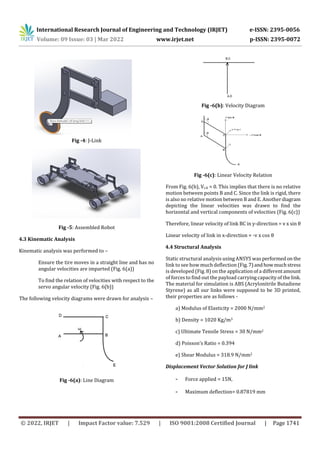
Fig -3(a) & (b): Displacement of the links
The (Fig.3 (a) & (b)) designs show the displacement of the
link when it approaches a bump and a ditch respectively.
4.2 Modelling
All the links were modeled and assembledusingSolidWorks.
These design modifications were later incorporated before
the fabrication of the robot. The final model of assembled
links (Fig. 4) and robot (Fig. 5) are given below. The
tabulated summary of dimensions is mentioned below.](https://image.slidesharecdn.com/irjet-v9i3320-220920094802-63ace12c/85/Smart-Terrain-Adaptive-Robotic-Suspension-System-S-T-A-R-S-S-3-320.jpg)
![International Research Journal of Engineering and Technology (IRJET) e-ISSN: 2395-0056
Volume: 09 Issue: 03 | Mar 2022 www.irjet.net p-ISSN: 2395-0072
© 2022, IRJET | Impact Factor value: 7.529 | ISO 9001:2008 Certified Journal | Page 1743
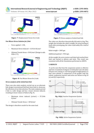
As evident from the graphs, the accuracy of our suspension
system would be about 0.5 degrees.
Even though there were minor vibrations in the chassis, the
robot’s auto-stabilization works perfectly.
6. CONCLUSIONS
The primary goal of achieving a robotic suspension
system that maintains a nearly horizontal chassis
through a variety of terrains was largely satisfied.
The negative feedback loop in the code resulted in
extremely high accuracies of about 0.1 degrees,
which is way more than what was aimed for.
Also, the code written resultedinauto–stabilization,
and recovery from any angle, something which
wasn't intended to be one of the objectives, to begin
with. Two major problems with the design were
identified.
There was an additional supporting strip attached
to the terrain to prevent the wheels from diverging,
and instead follow a steady straight path along the
track.
The robotic suspension system is designed for a
slow-moving robot as most space exploration
robots are slow-moving. The same suspension
system may not work as efficientlyfora fast-moving
robot. Thus it is important to note that robots with
these suspensionsystemsshouldideallynotbeused
for high-speed operations.
The prototype that we have created did not have a
motor driving circuit or a steering mechanism as
they were both beyond the objective of the project.
Changes that can be implemented for Full- Scale Model
The speed (in rpm) of each wheel is equal to 10.
After thinking about the suspension system’s
practicality, we agreed that it would be effective for
relatively higher speeds as well.
The servo motors used will be more than suffice for
our prototype due to their accurate response.
However, for a scaled-up version of the prototype,
stepper motors will be needed to handle
comparatively heavier loads.
Code for a larger prototype can include speed and
acceleration control of the stepper motor to avoid
jerks. Advanced control systems and higher-order
stabilization will make the actuation vibration jerk
free.
An Arduino Uno’s prowess of storing local variables
is not very efficient. This means that higher
processing power will be requiredforthecontroller
to perform other tasks.
The code used for interfacing the microcontroller,
IMU, and the servo motors are not limited to the
prototype that we have created. Changing the
mapping using the equations in the code should
work for a scaled-up model as well.
Although the material used is durable and may
sustain loads of up to 6 kg, it is recommended that a
stronger yet lighter material, like composites, be
used for a scaled-up model or greater payload
capacity.
For a scaled-up model, a ball bearing would be
much ideal to join the 2 links as it provides
smoother mobility and higher stability.
REFERENCES
[1] Yuxin Zhanga, Xinjie Zhanga, Min Zhana, Konghui
Guoa, Fuquan Zhaoc, Zongwei Liu, “Studyona novel
hydraulic pumping regenerative suspension for
vehicles," In Press, Corrected Proof, Available
online, 2014
[2] BMW Dynamic Drive, Insights, Technology Guide.
[3] Karl Iagnemma, Adam Rzepniewski and Steven
Dubowsky, “Control of Robotic Vehicles with
Actively Articulated SuspensionsinRoughTerrain,”
Autonomous Robots 14, 5–16, 2003
[4] Kazuo Tani, Osamu Matsumoto, Shuuji Kajita,
Nobumasa Shirai, “Wheeled Robots to Overcome
Ground Uneveness in Construction Areas,”
Mechanical Engineering Laboratory, Namiki,
Tsukuba, Japan
[5] Adibi Asl, H. Rideout, G. , "Using lead vehicle
response to generate preview functions for active
suspension of convoy vehicles", American Control
Conference (ACC), Pages 4594 – 4600, 2010
[6] Panshuo Li, James Lam , Kie Chung Cheung, “Multi-
objective control for active vehicle suspension with
wheelbase preview,” Journal of Sound and
Vibration, Volume 333, Pages 5269–5282, 2014.
[7] MPU 6050 Datasheet -
http://www.invensense.com/mems/gyro/documen
ts/PS-MPU-6000A-00v3.4.pdf
[8] Turnigy TGY-4409MD -
http://www.hobbyking.com/hobbyking/store/__24](https://image.slidesharecdn.com/irjet-v9i3320-220920094802-63ace12c/85/Smart-Terrain-Adaptive-Robotic-Suspension-System-S-T-A-R-S-S-6-320.jpg)
![International Research Journal of Engineering and Technology (IRJET) e-ISSN: 2395-0056
Volume: 09 Issue: 03 | Mar 2022 www.irjet.net p-ISSN: 2395-0072
© 2022, IRJET | Impact Factor value: 7.529 | ISO 9001:2008 Certified Journal | Page 1744
578__Turnigy_TGY_4409MD_Metal_Gea
r_Digital_Servo_9_45kg_0_11sec_44g.htl
[9] Arduino Uno Technical overview
http://www.arduino.cc/en/Main/ArduinoBoardUn
o
[10] https://en.wikipedia.org/wiki/Rocker-bogie
[11] www.electronicparts.com
[12] Mars Pathfinder: www.mpf.jpl.nasa.gov](https://image.slidesharecdn.com/irjet-v9i3320-220920094802-63ace12c/85/Smart-Terrain-Adaptive-Robotic-Suspension-System-S-T-A-R-S-S-7-320.jpg)

This document describes the design of a smart terrain adaptive robotic suspension system (S.T.A.R.S.S.) that aims to maintain a nearly horizontal chassis over various terrains. The suspension uses a modified parallel four-bar linkage mechanism and active control via an IMU, microcontroller, and servo motors. Kinematic and structural analyses were performed on the linkage design in simulation software. A prototype was built and tested on an undulating surface track while monitoring chassis attitude. Multiple tests resulted in code improvements and fulfillment of the objective of stabilizing the chassis.


